
I had a spare diff laying around after my rear-end overhaul, so I decided to take it apart completely, just for fun. Beyond that I wanted to photograph the process for others to see how it all goes together. Diff assembly is not a big secret or anything, but it seems like it is one of those things that most DIY'ers shy away from since you cannot just slap it back together again since you need to set the pre-load on the various bearings and whatnot. This post has ZERO information about how to put it all back together properly because you need specialty tools, serious know-how and an assortment of new bearings and shims. This is just the fun stuff...taking it all apart!
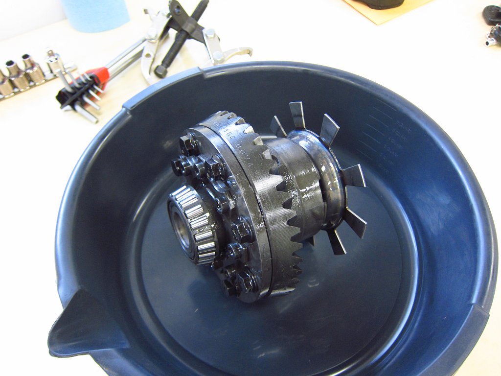
So, what did I take apart? The differential is a 168mm "small case" LSD unit with unknown mileage (probably over 200k miles) that could have been confused for a coffee can full of rocks when it was in service. This bastard was getting LOUD!
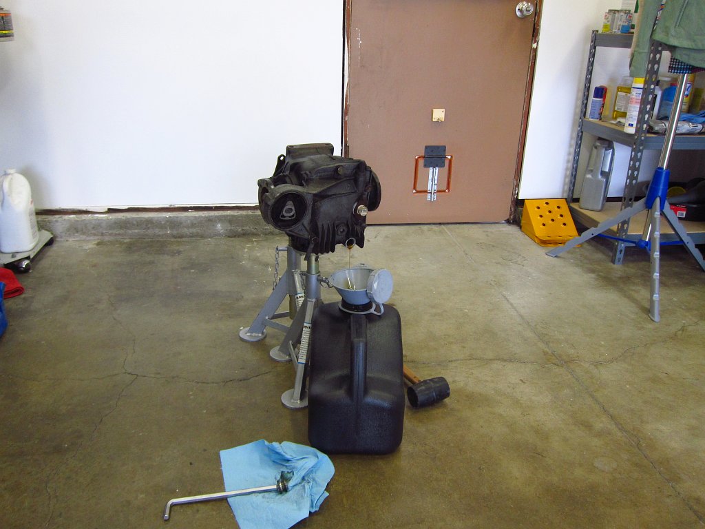
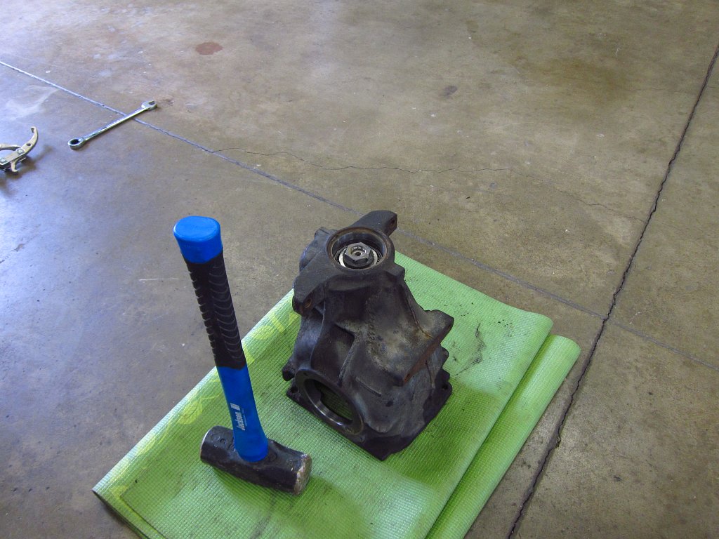
So, first things first. You will want to drain as much of the fluid as possible. The gear oil is thick and I left it sitting like this for a few hours, and I rotated the output flanges 15 degrees or so every 15 minutes to try to get as much of it out of the LSD unit as possible. I stuck an old wheel bearing under the front of the diff to tilt it back to help with the draining.
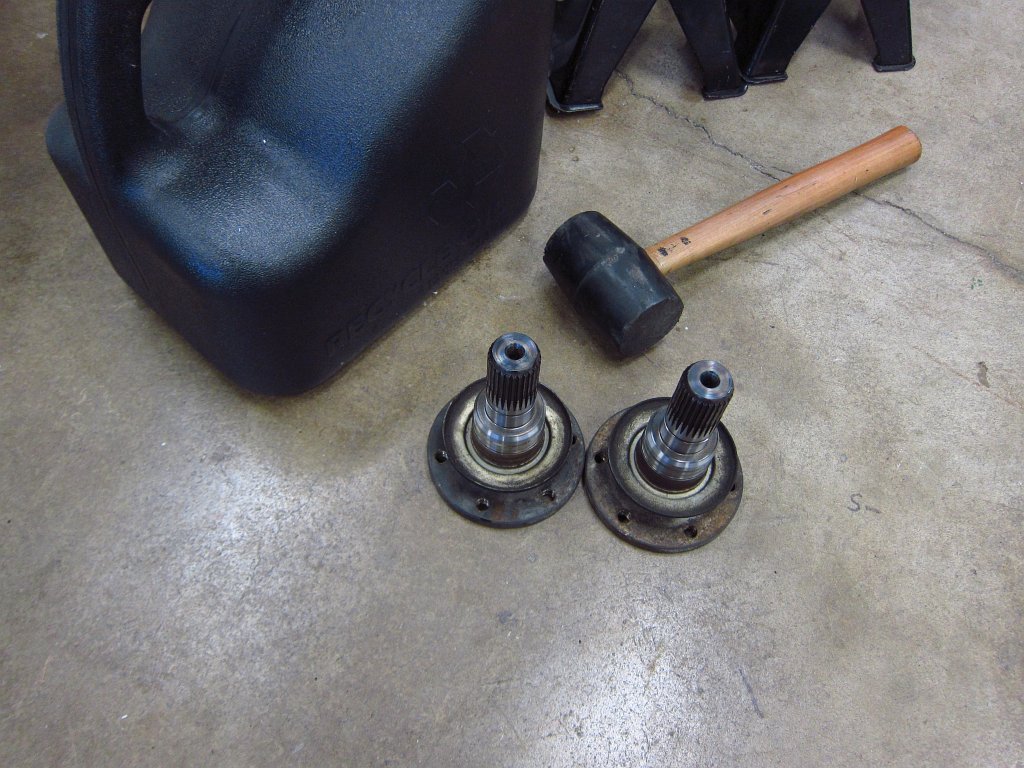
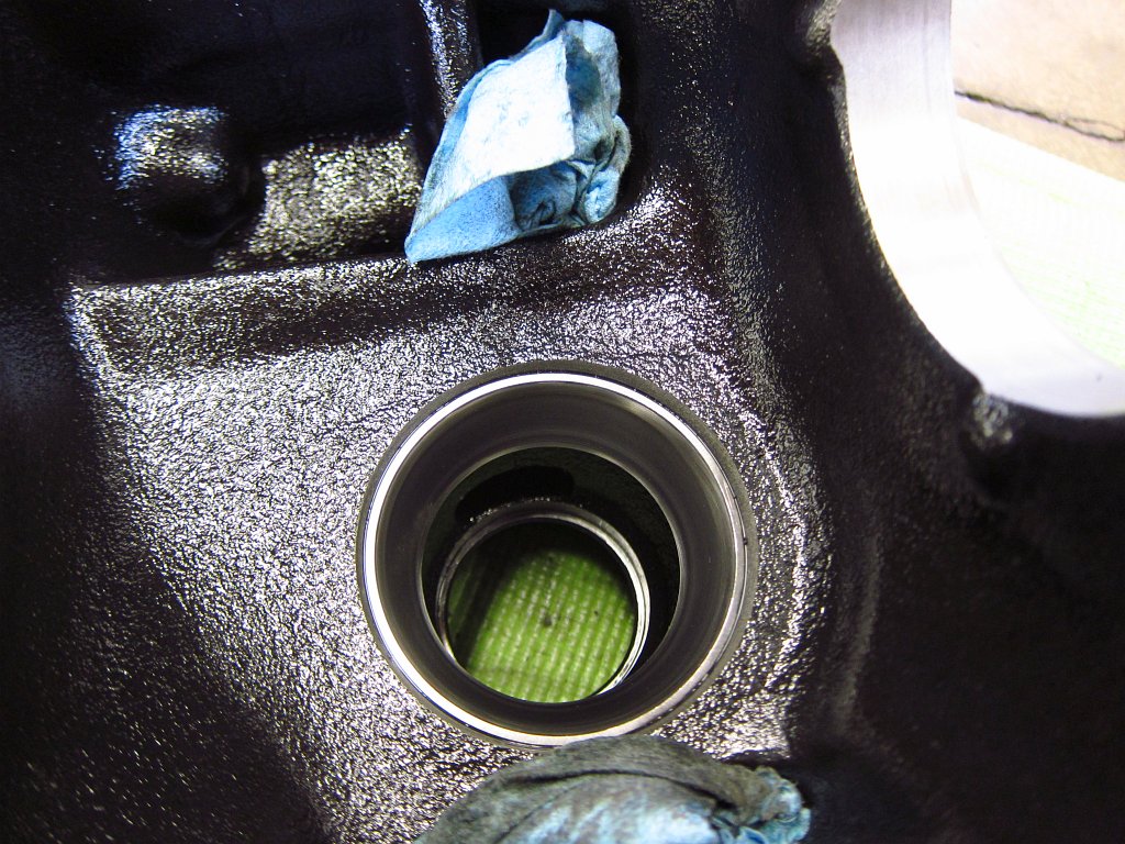
Once the fluid was drained, I pulled the output flanges off. This was easily done by hand (ignore the mallet!).
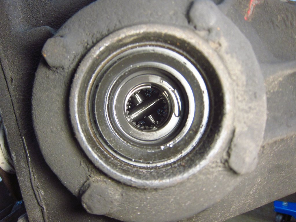
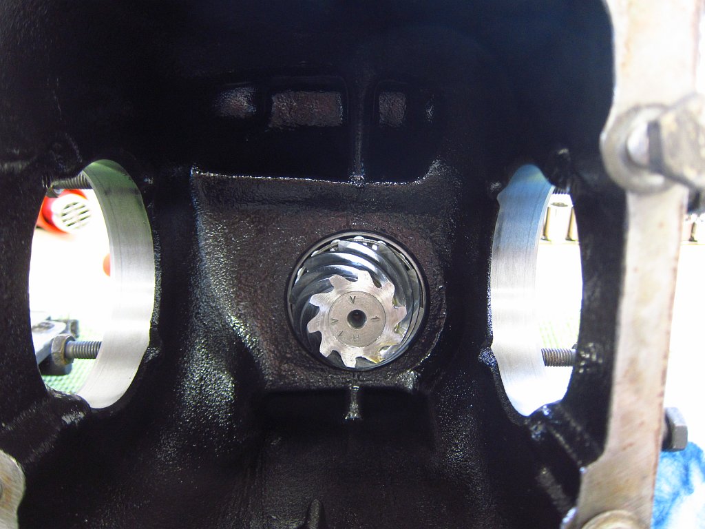
If you look into the diff, you can see some of the inner workings which we will get to soon.
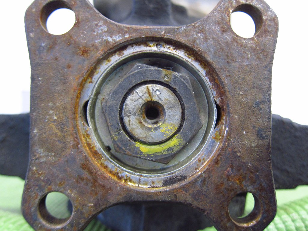
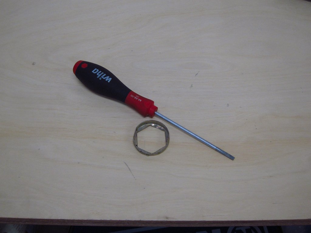
The next step is to deal with what is (IMO) the hardest part. The input flange is held on with a 30mm nut. First pry out the lock plate.
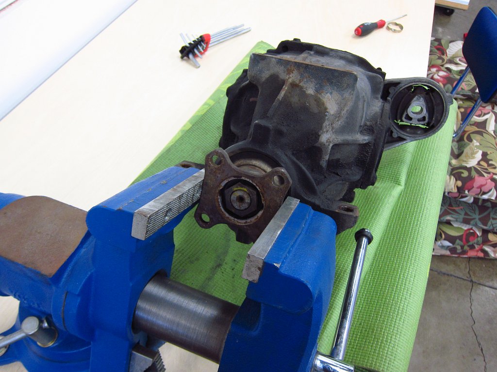
Since the nut was torqued down VERY tightly, and a little rusty, I heated it with a MAP torch for a couple of minutes to try to fracture any rust in the threads. After that I stuck the input flange into my vise and attacked it with a poor-man's impact wrench (6lb sledge and 18" breaker bar). This goes against most of my rules because I dislike abusing tools, and I generally avoid hammering metal with metal. But, since I am not planning to use or rebuild this diff, and the rubber mallet just was not getting the job done, I gave the nut a few whacks to break it free.
Note that you are venturing past the point of no return here. Once you loosen this nut, that's it, the pre-load on the bearings is off and the vast majority of DIY'ers do not have the tools needed to reinstall the nut while getting the shaft runout dialed in.

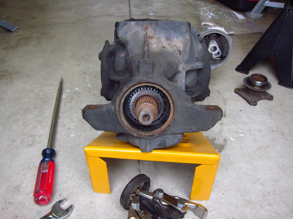
Getting the flange out was super easy. One turn of the gear pullers broke it loose on the splines and I could pull it off with my hands.


After that I turned the jaws around and pulled out the input shaft seal.
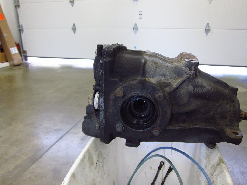
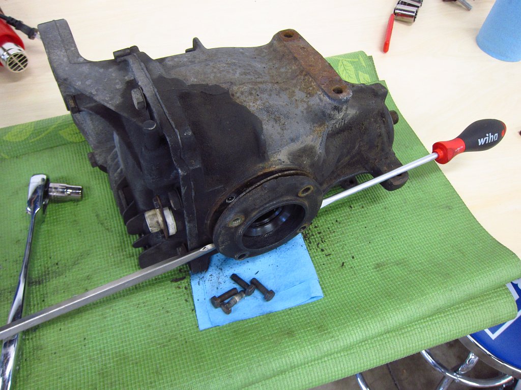
Next I removed the outer bearing race assemblies. First I used a wire brush to knock off 26 years of accumulated dirt and grease so that my 13mm socket would not get full of crap. Again, this is more or less a point of no return. The flange held by the 4 bolts is shimmed to get the bearings loaded properly, and things might not go back together with the proper clearances after this.
Also, this is not the order you would want to do things if you actually cared about the differential. These output bearing race assemblies are holding the actual differential unit in place inside the housing, and yanking them out now will cause the diff to fall down inside the unit and roll around. You would normally want to take the cover off and jam some rags around the diff unit to support it, or have a second set of hands in there holding it while you pull the assemblies off. I left the cover on because I don't really care about this diff and I did not want stinky gear oil oozing out all over my bench.
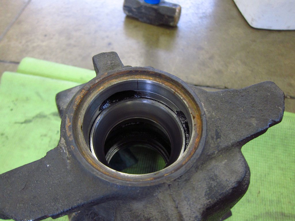
With the bolts out, gently wiggle the assembly out. There is a rubber o-ring around the perimeter that makes this a tight fit, but they should come right out with a little effort.
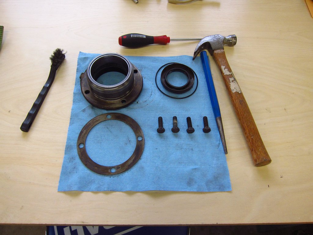
Here is the assembly, mostly disassembled. A hammer and punch get the shaft seal out pretty easily. The actual bearing race is pressed in and I left it in the unit since I do not have the tools to remove it without causing serious damage.
Voila, one loose LSD unit!
Next I removed the pinion gear from the housing. Again, my method probably doesn't fall under the category of "best practices" bit it worked just fine for my purposes here. Thread the nut on and a few whacks with the 6lb sledge popped it free of the outer bearing's inner race. The nut is important for two reasons. One, it prevents the threads on the shaft from getting mangled. Two, it prevents the pinion gear from flying through and striking whatever is under the diff (in this case, one of my wife's yoga mats which is now mine...she is a very tolerant woman lol).
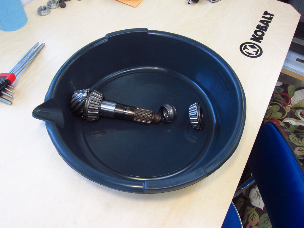
Here is why working with these suckers is not a simple DIY affair. The input shaft has two bearings pressed on (the outer races remained pressed inside the diff housing). There is a crush sleeve between them (and some shims according to RealOEM but I did not find any in here), and applying the proper clearances requires you to press the bearings in precisely and adjust the 30mm flange nut accordingly.
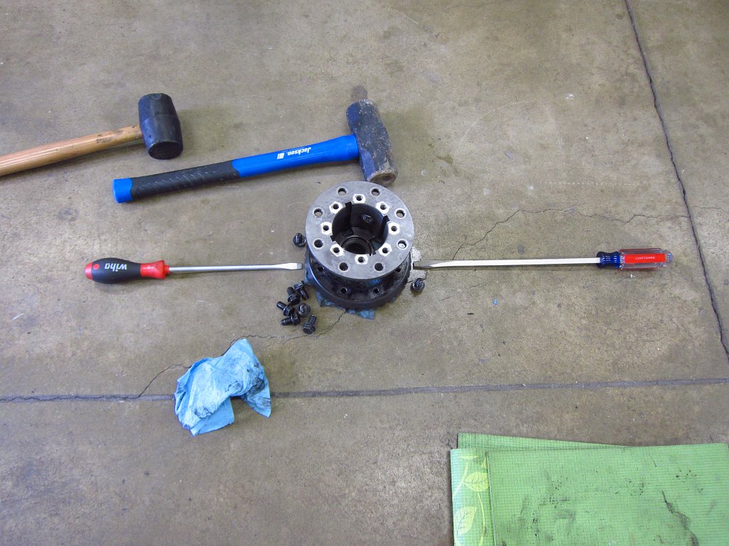
The next order of business was taking apart the LSD unit. I started by prying off the speedometer sender wheel which was pretty simple to do with some large screwdrivers.
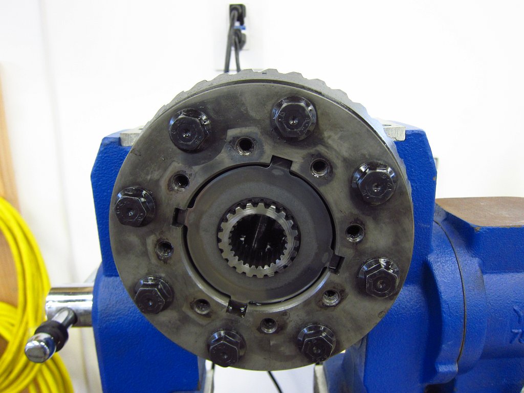
Next I gripped the LSD body in the vise (again, this isn't "best practices" here) so that I could deal with the bolts and socket cap screws. The hex screws in the middle are very tight, have super tough threadlocker on them and are under immense tension from the Belleville washers inside. Loosen them half a turn at a time in a star pattern until the big flange is no longer subject to the washers' force.
After that you can start pulling stuff out. The plates and washers inside are what make the LSD do its thing.
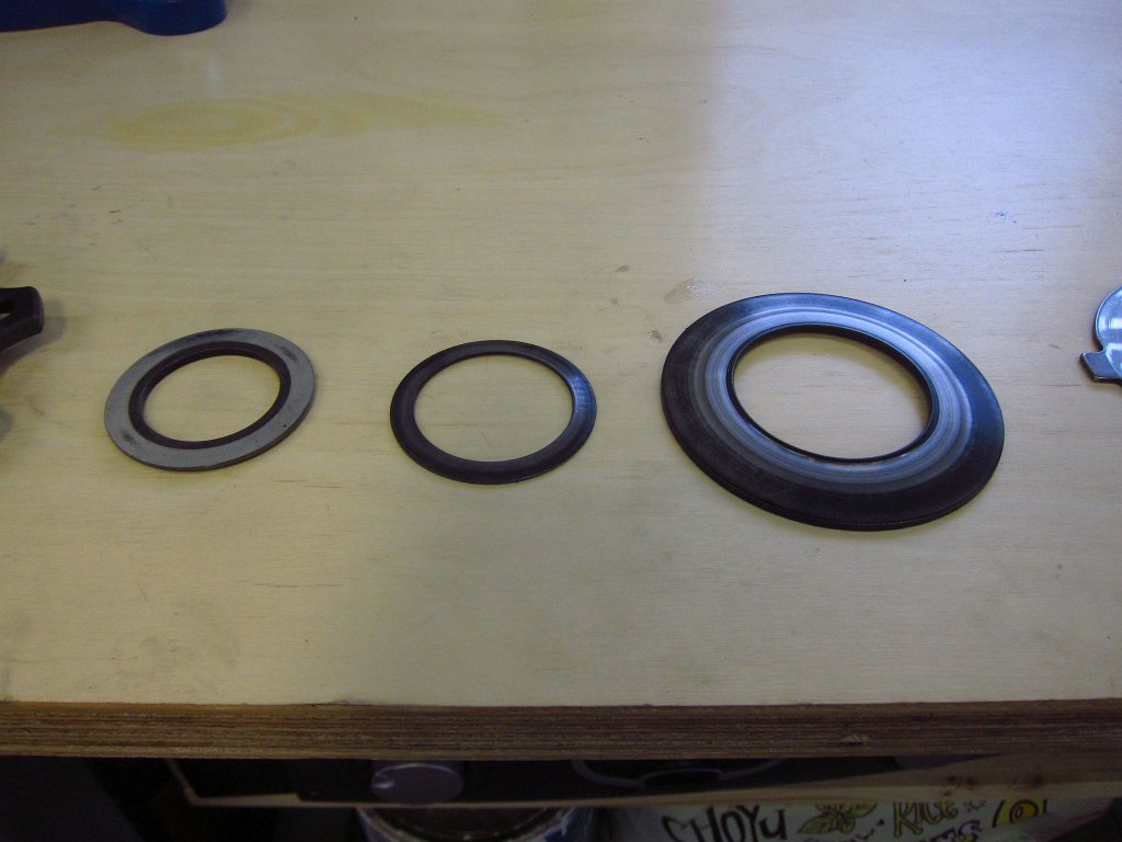
Here is one set of Belleville washers from one side. These provide the compression force on the friction plates that set the torque bias and slip characteristics. These aren't shown in the actual order in which they are stacked...the left and middle ones are swapped.
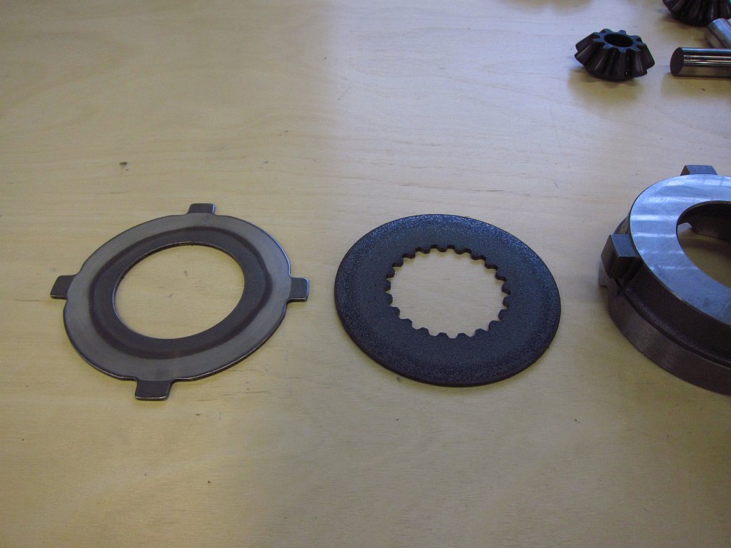
The splotched disc is the rough friction plate. There are two of these, and they are responsible for the slip characteristics as much as the pre-load from the Belleville washers.
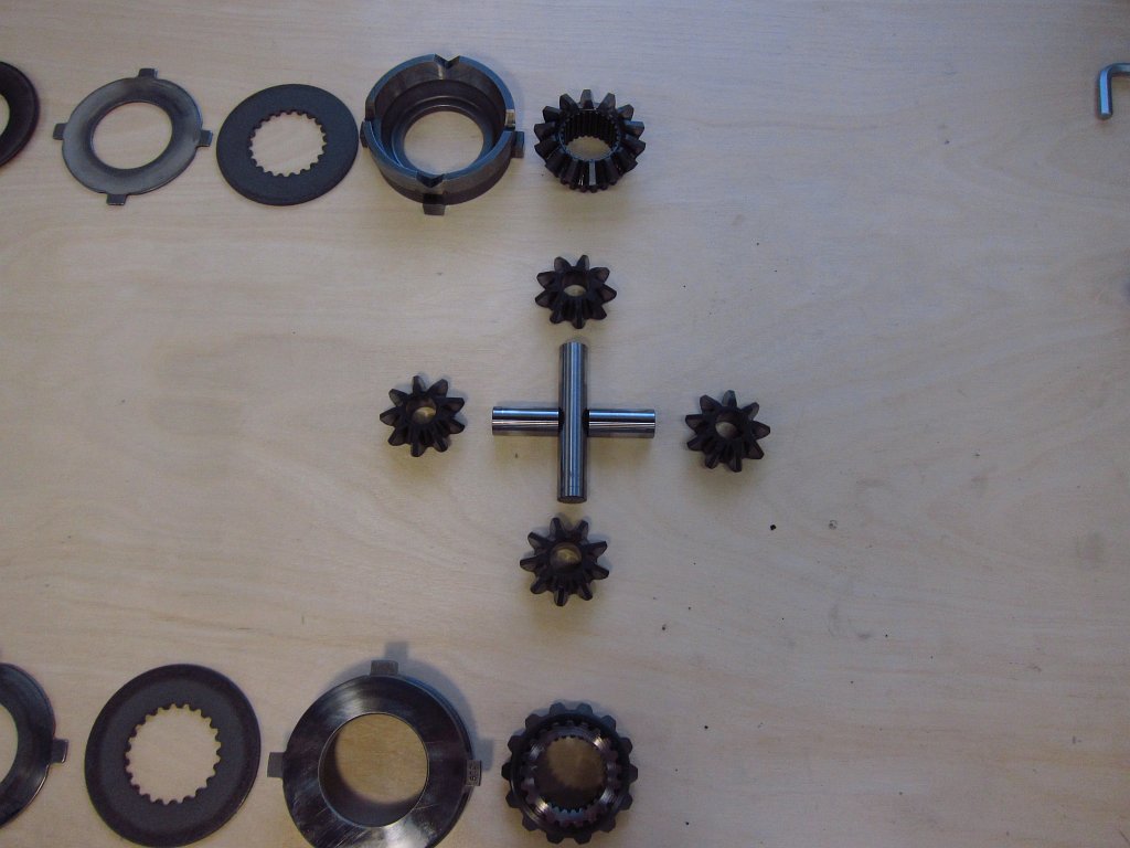
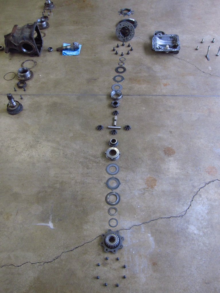
Here are the spider gears and side gears. The splines in the side gears are what ultimately transmit all of the torque into the output flanges (and thus the wheels).
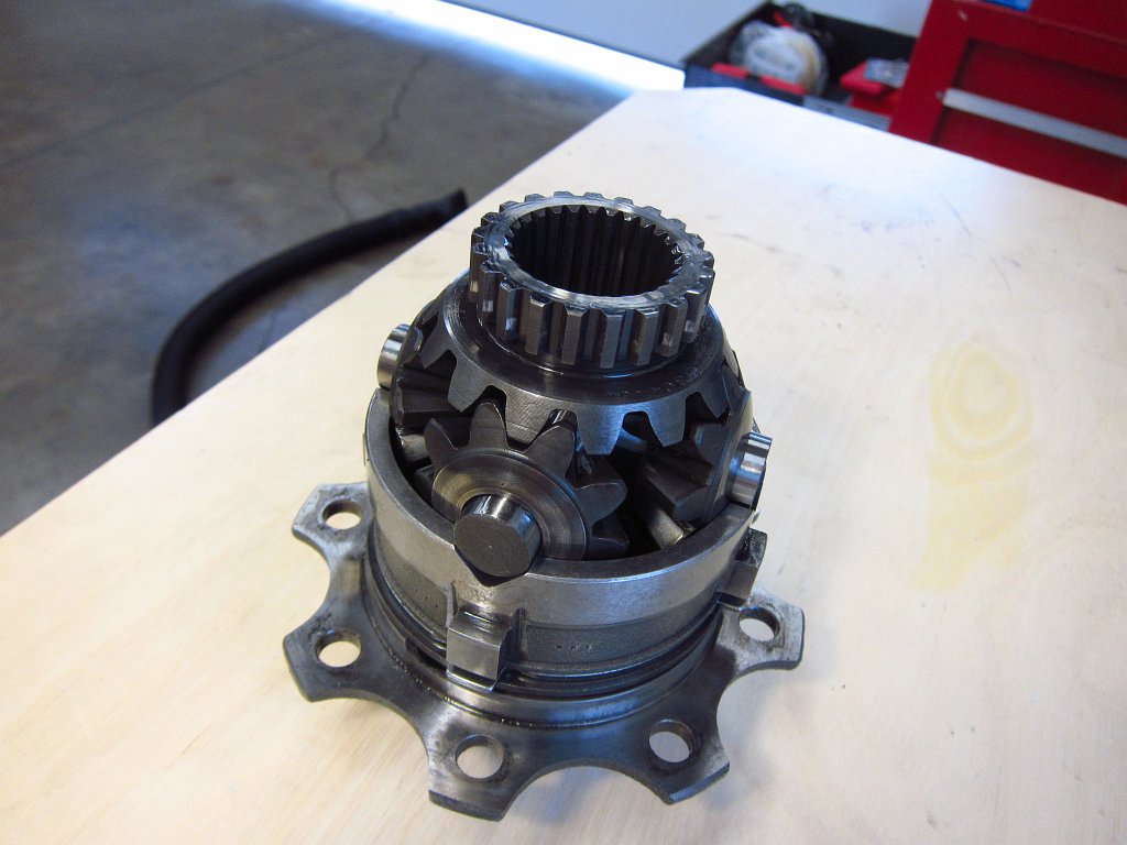
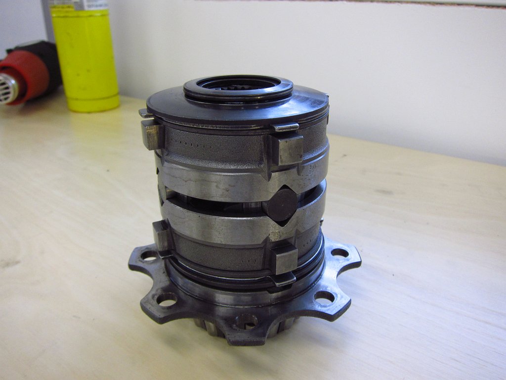
Here is the unit, partially stacked and fully stacked.
To remove the ring gear, you will need a little more brute force. The 15mm bolts have locking heads, super threadlocker and are torqued down tight. Once those are out, thread two opposing ones in a couple of turns by hand and tap them with the sledge to start pushing the ring gear off. It should slide right off.
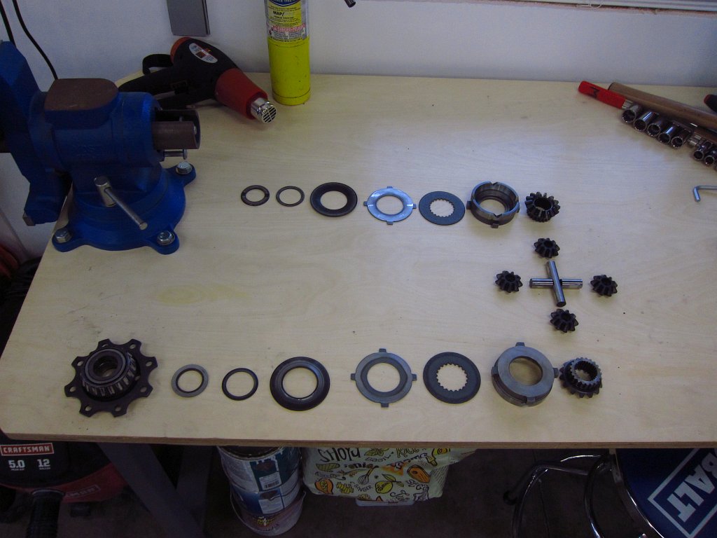
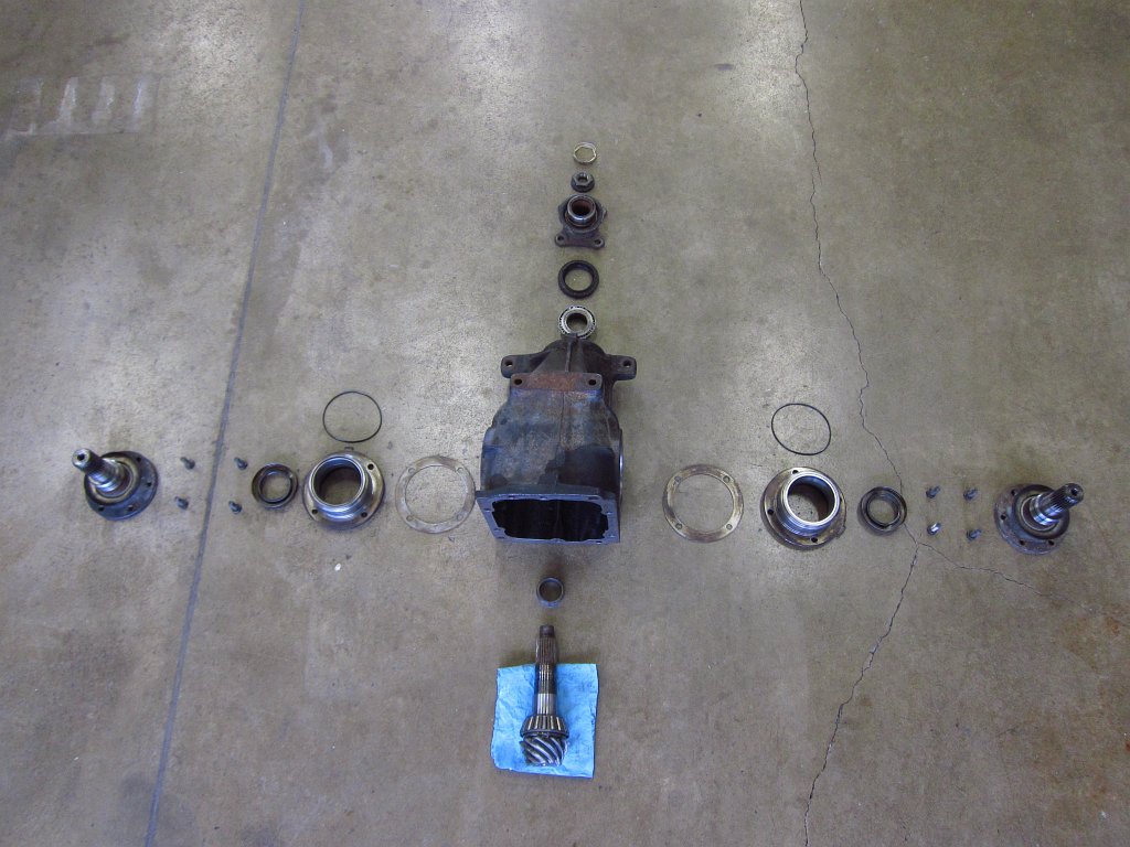
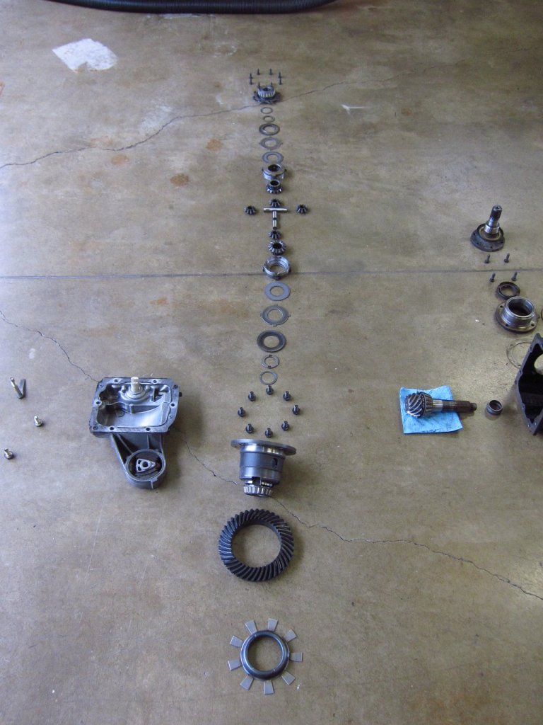
That was about it for my disassembly adventure. Again, no bearing races were removed because I did not want to cause significant damage to the unit since someone may want it for a rebuild or something. Before tossing all of the parts into some 5 gallon buckets with lids to protect them from moisture, I laid everything out in an exploded fashion. There really is not all that much to a LSD!

Finally, I would like to close by noting how much I hate the small of gear oil. It is stinky shit and I hate it. That is all.
So, what did I take apart? The differential is a 168mm "small case" LSD unit with unknown mileage (probably over 200k miles) that could have been confused for a coffee can full of rocks when it was in service. This bastard was getting LOUD!
So, first things first. You will want to drain as much of the fluid as possible. The gear oil is thick and I left it sitting like this for a few hours, and I rotated the output flanges 15 degrees or so every 15 minutes to try to get as much of it out of the LSD unit as possible. I stuck an old wheel bearing under the front of the diff to tilt it back to help with the draining.
Once the fluid was drained, I pulled the output flanges off. This was easily done by hand (ignore the mallet!).
If you look into the diff, you can see some of the inner workings which we will get to soon.
The next step is to deal with what is (IMO) the hardest part. The input flange is held on with a 30mm nut. First pry out the lock plate.
Since the nut was torqued down VERY tightly, and a little rusty, I heated it with a MAP torch for a couple of minutes to try to fracture any rust in the threads. After that I stuck the input flange into my vise and attacked it with a poor-man's impact wrench (6lb sledge and 18" breaker bar). This goes against most of my rules because I dislike abusing tools, and I generally avoid hammering metal with metal. But, since I am not planning to use or rebuild this diff, and the rubber mallet just was not getting the job done, I gave the nut a few whacks to break it free.
Note that you are venturing past the point of no return here. Once you loosen this nut, that's it, the pre-load on the bearings is off and the vast majority of DIY'ers do not have the tools needed to reinstall the nut while getting the shaft runout dialed in.
Getting the flange out was super easy. One turn of the gear pullers broke it loose on the splines and I could pull it off with my hands.
After that I turned the jaws around and pulled out the input shaft seal.
Next I removed the outer bearing race assemblies. First I used a wire brush to knock off 26 years of accumulated dirt and grease so that my 13mm socket would not get full of crap. Again, this is more or less a point of no return. The flange held by the 4 bolts is shimmed to get the bearings loaded properly, and things might not go back together with the proper clearances after this.
Also, this is not the order you would want to do things if you actually cared about the differential. These output bearing race assemblies are holding the actual differential unit in place inside the housing, and yanking them out now will cause the diff to fall down inside the unit and roll around. You would normally want to take the cover off and jam some rags around the diff unit to support it, or have a second set of hands in there holding it while you pull the assemblies off. I left the cover on because I don't really care about this diff and I did not want stinky gear oil oozing out all over my bench.
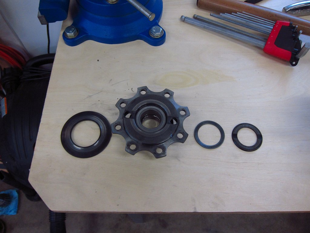
With the bolts out, gently wiggle the assembly out. There is a rubber o-ring around the perimeter that makes this a tight fit, but they should come right out with a little effort.
Here is the assembly, mostly disassembled. A hammer and punch get the shaft seal out pretty easily. The actual bearing race is pressed in and I left it in the unit since I do not have the tools to remove it without causing serious damage.
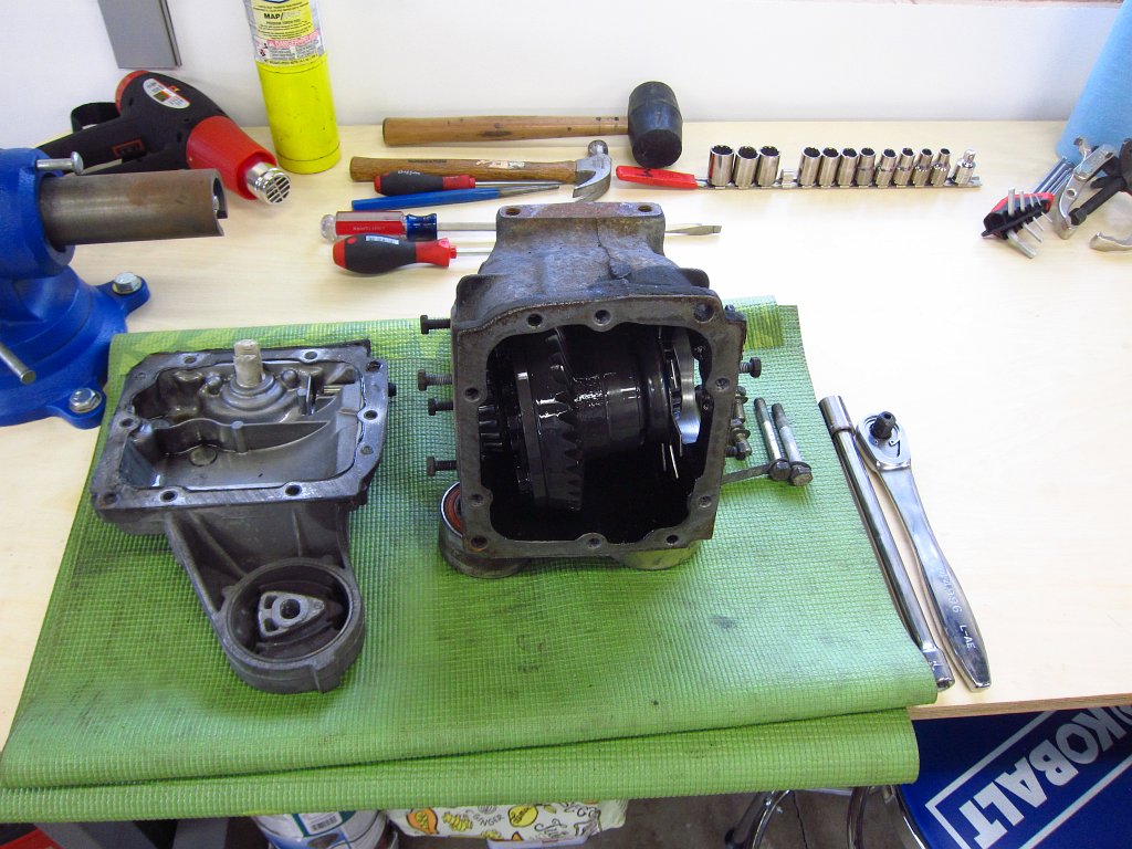
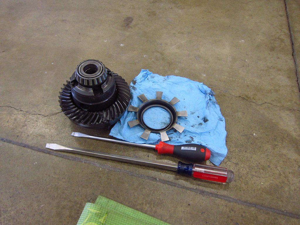
Voila, one loose LSD unit!
Next I removed the pinion gear from the housing. Again, my method probably doesn't fall under the category of "best practices" bit it worked just fine for my purposes here. Thread the nut on and a few whacks with the 6lb sledge popped it free of the outer bearing's inner race. The nut is important for two reasons. One, it prevents the threads on the shaft from getting mangled. Two, it prevents the pinion gear from flying through and striking whatever is under the diff (in this case, one of my wife's yoga mats which is now mine...she is a very tolerant woman lol).
Here is why working with these suckers is not a simple DIY affair. The input shaft has two bearings pressed on (the outer races remained pressed inside the diff housing). There is a crush sleeve between them (and some shims according to RealOEM but I did not find any in here), and applying the proper clearances requires you to press the bearings in precisely and adjust the 30mm flange nut accordingly.
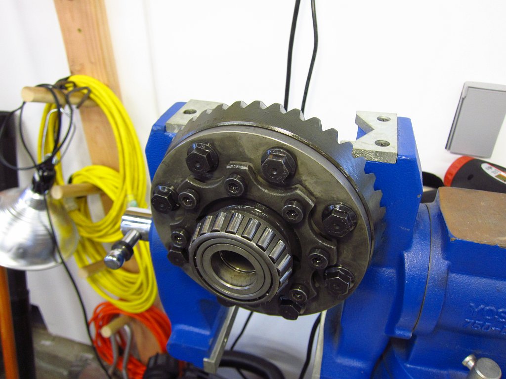
The next order of business was taking apart the LSD unit. I started by prying off the speedometer sender wheel which was pretty simple to do with some large screwdrivers.
Next I gripped the LSD body in the vise (again, this isn't "best practices" here) so that I could deal with the bolts and socket cap screws. The hex screws in the middle are very tight, have super tough threadlocker on them and are under immense tension from the Belleville washers inside. Loosen them half a turn at a time in a star pattern until the big flange is no longer subject to the washers' force.
After that you can start pulling stuff out. The plates and washers inside are what make the LSD do its thing.
Here is one set of Belleville washers from one side. These provide the compression force on the friction plates that set the torque bias and slip characteristics. These aren't shown in the actual order in which they are stacked...the left and middle ones are swapped.
The splotched disc is the rough friction plate. There are two of these, and they are responsible for the slip characteristics as much as the pre-load from the Belleville washers.
Here are the spider gears and side gears. The splines in the side gears are what ultimately transmit all of the torque into the output flanges (and thus the wheels).
Here is the unit, partially stacked and fully stacked.
To remove the ring gear, you will need a little more brute force. The 15mm bolts have locking heads, super threadlocker and are torqued down tight. Once those are out, thread two opposing ones in a couple of turns by hand and tap them with the sledge to start pushing the ring gear off. It should slide right off.
That was about it for my disassembly adventure. Again, no bearing races were removed because I did not want to cause significant damage to the unit since someone may want it for a rebuild or something. Before tossing all of the parts into some 5 gallon buckets with lids to protect them from moisture, I laid everything out in an exploded fashion. There really is not all that much to a LSD!
Finally, I would like to close by noting how much I hate the small of gear oil. It is stinky shit and I hate it. That is all.


Comment