
Quote:
Originally Posted by JGood
...
__________________________________________________
How to read the wire diagrams:
Go here:
http://www.wedophones.com/BMWManualsLead.htm
Find the manual for your car or engine, whatever side you are doing pinouts for.
Open the manual, and skip to the section that starts talking about power distribution and various under hood parts.
This is what it will look like:
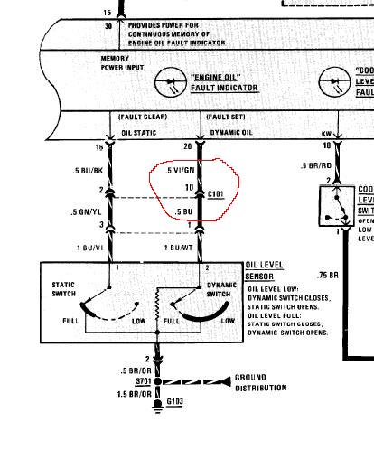
You want to look for any instance of either c101 or x20, such as what is circled. C101 is the e30 engine connector, x20 is the e36/e34 connector. So if you are looking at an e30 manual, just look for c101. When you look at the e36/e34 manual, look for x20.
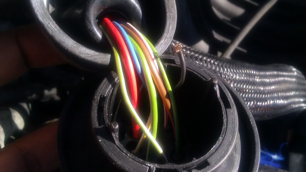
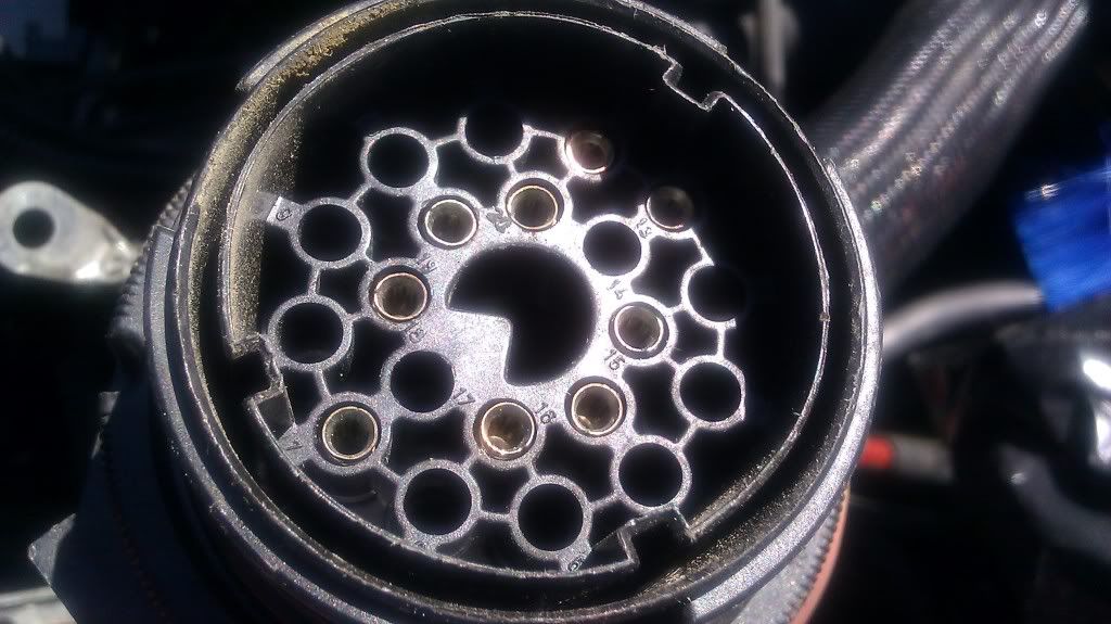
The c101 connector is the big round connector on your firewall. It has 20 or so pins on it (it’s a square connector with less pins if you have an 84-85 model). Each pin will be drawn out in this manual. Here, in the example, we are looking at pin 10 (see the 10 next to where it says c101).
The curved lines show which way the signal is coming through the connector. In this example, you see it’s coming FROM the oil level sensor, TO the engine oil fault indicator (the oil level light in your car).
The VI/GN and BU/WT are the colors of the wires. The wire between the sensor and the connector is blue with a white stripe, the wire between the connector and the warning light is Violet with a green stripe.
The .5 next to the color is the wire size. Apparently this is in millimeters squared. .5 will be a little wire, .75 medium, 1 is big. (I think).
You now know what color the wire is on the engine side, what color t is on the body side, what pin it is in the connector, and what its function is.
The schematics are generally laid out as power (+12 volts) from the top of the pages, to ground at the bottom of the pages. Further details of what various symbols mean can be found in the beginning pages of the manuals.
================================================== =====
I have a bunch of wires how do I take one wire from the harness and say, yes, this is for the so and so (alternator)...Right now I am trying to label my S52 wiring harness to my e30 m3, any help is appreciated.
If I missed something let me know, I really want to get this project up and running, it has been sitting for too long. When I finish swap, I have the OBD1 parts to add.
my organization is set up like this.
label wiring harness
lock oil pump bolt
mount oil pan
fit a m42 radiator
fit a brake booster
install engine
tell me if I am on the right track, this is my first swap.
Originally Posted by JGood
...
__________________________________________________
How to read the wire diagrams:
Go here:
http://www.wedophones.com/BMWManualsLead.htm
Find the manual for your car or engine, whatever side you are doing pinouts for.
Open the manual, and skip to the section that starts talking about power distribution and various under hood parts.
This is what it will look like:
You want to look for any instance of either c101 or x20, such as what is circled. C101 is the e30 engine connector, x20 is the e36/e34 connector. So if you are looking at an e30 manual, just look for c101. When you look at the e36/e34 manual, look for x20.
The c101 connector is the big round connector on your firewall. It has 20 or so pins on it (it’s a square connector with less pins if you have an 84-85 model). Each pin will be drawn out in this manual. Here, in the example, we are looking at pin 10 (see the 10 next to where it says c101).
The curved lines show which way the signal is coming through the connector. In this example, you see it’s coming FROM the oil level sensor, TO the engine oil fault indicator (the oil level light in your car).
The VI/GN and BU/WT are the colors of the wires. The wire between the sensor and the connector is blue with a white stripe, the wire between the connector and the warning light is Violet with a green stripe.
The .5 next to the color is the wire size. Apparently this is in millimeters squared. .5 will be a little wire, .75 medium, 1 is big. (I think).
You now know what color the wire is on the engine side, what color t is on the body side, what pin it is in the connector, and what its function is.
The schematics are generally laid out as power (+12 volts) from the top of the pages, to ground at the bottom of the pages. Further details of what various symbols mean can be found in the beginning pages of the manuals.
================================================== =====
I have a bunch of wires how do I take one wire from the harness and say, yes, this is for the so and so (alternator)...Right now I am trying to label my S52 wiring harness to my e30 m3, any help is appreciated.
If I missed something let me know, I really want to get this project up and running, it has been sitting for too long. When I finish swap, I have the OBD1 parts to add.
my organization is set up like this.
label wiring harness
lock oil pump bolt
mount oil pan
fit a m42 radiator
fit a brake booster
install engine
tell me if I am on the right track, this is my first swap.


Comment