
Over the last few days, I've been finishing up the board design that will house all the components and fit into the chassis. Here's a few iterations I was printing on card stock, just working on the physical fitment and the couple of critical connector positions.
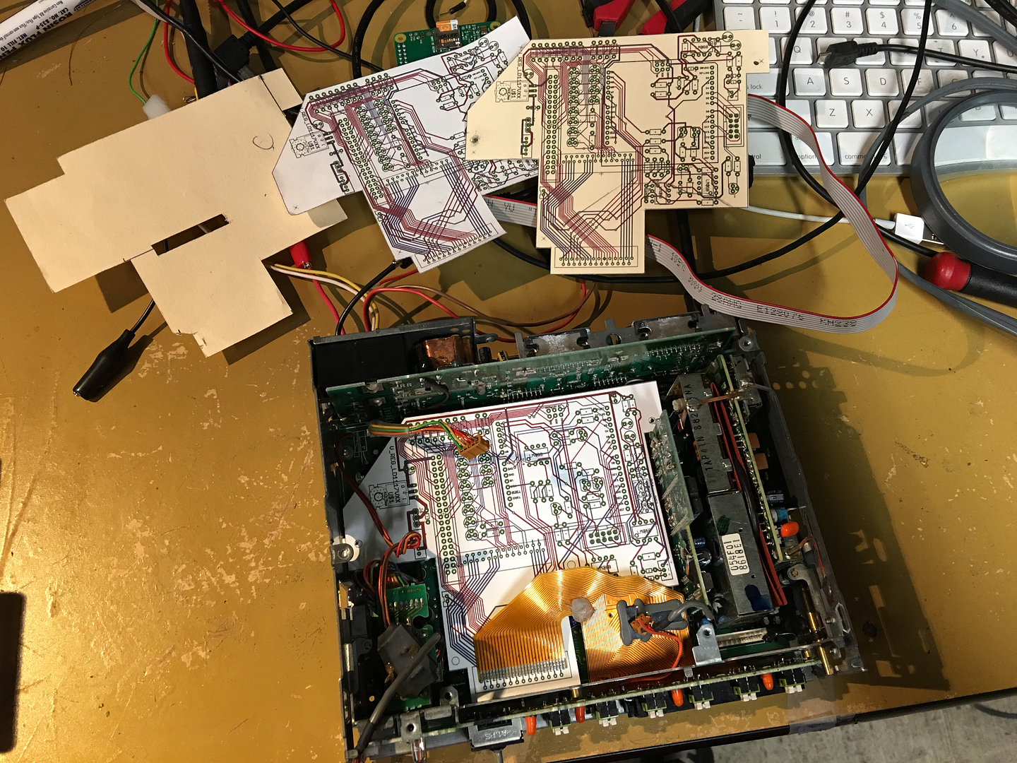
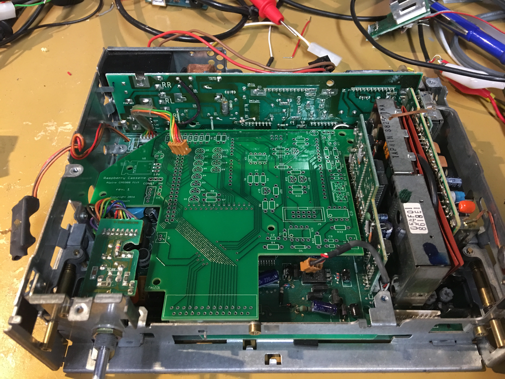
The last task I hadn't done on the HW hacking side was figuring out where to grab the radio output signal that will become an audio input to the Pi. I needed the post-mix (so the different AM/FM/WB radio modules had already been mixed onto the same stereo bus) but pre-processing like EQ and volume, since I will be handling that myself.
I lucked out with this one. That 3-pin connector I mentioned in my last post that carries the tape deck's output - it turns out, that connector's base on the main board is right next to the pins that contain exactly the stereo signal I want. So I repurposed the tape line-level input to be a radio line-level output by cutting the L/R traces originally running to the connector base, then soldering little jumpers from the connector base to the radio output right next to it. Works like a charm! The signal is a little weak for line-level though so I've added a simple preamp stage to my board to boost it up before leaving the chassis to hook into the USB sound card.
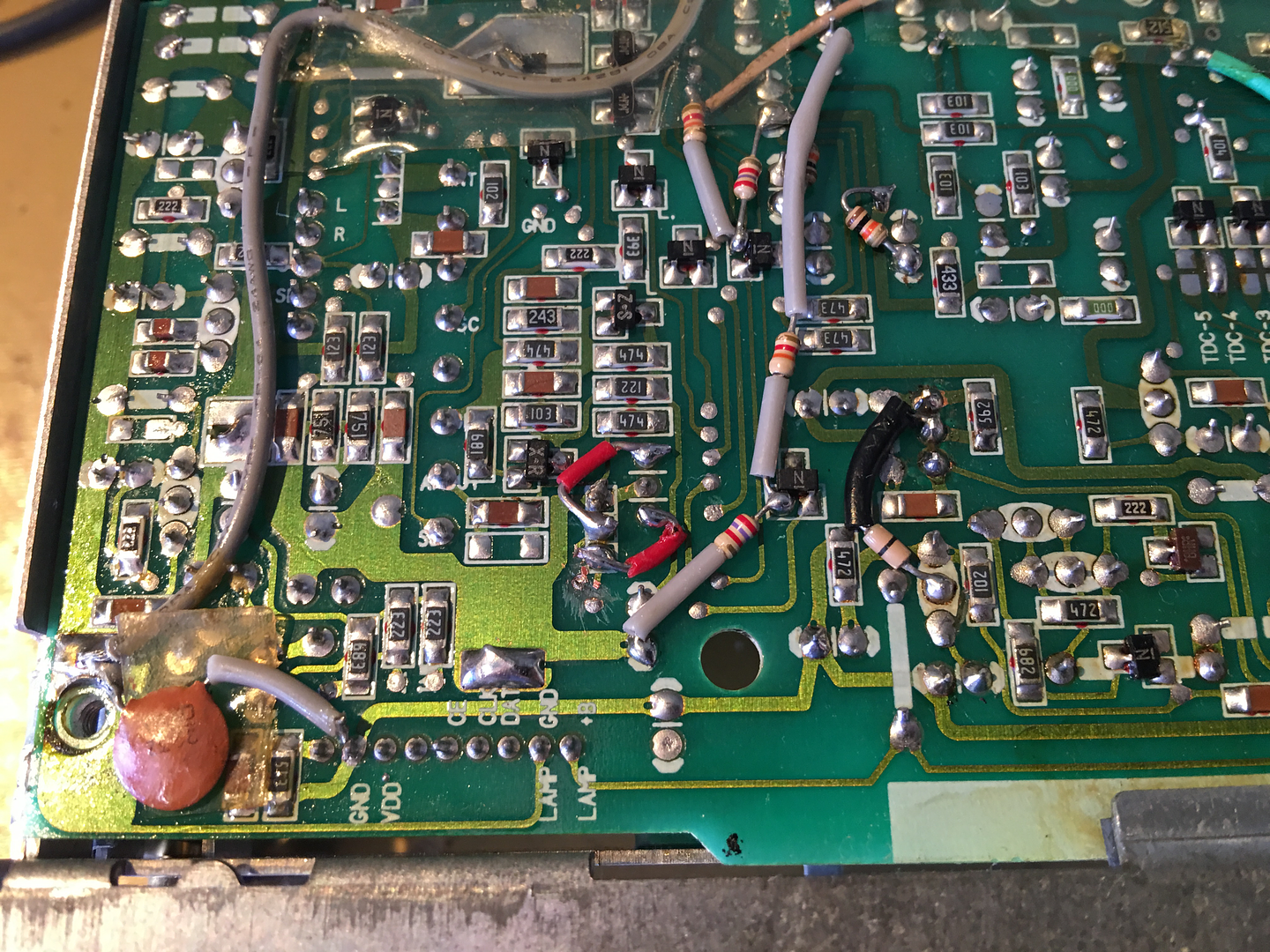
Here, near the bottom center, you can see the two traces I've scratched out. These were leading to the 3-pin connector's base
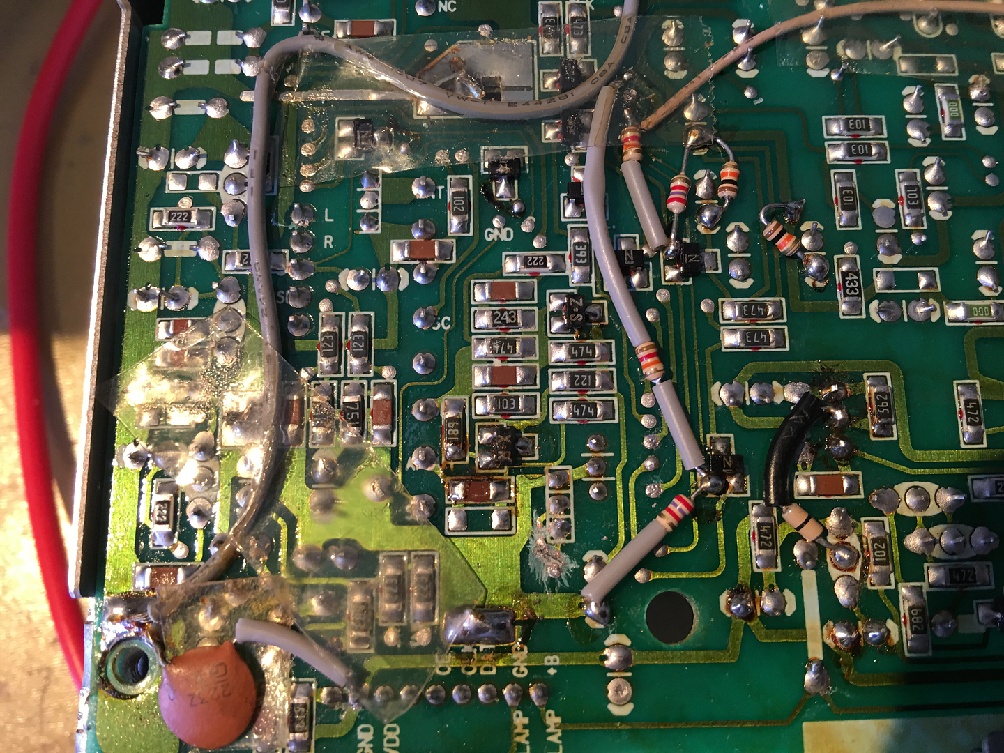
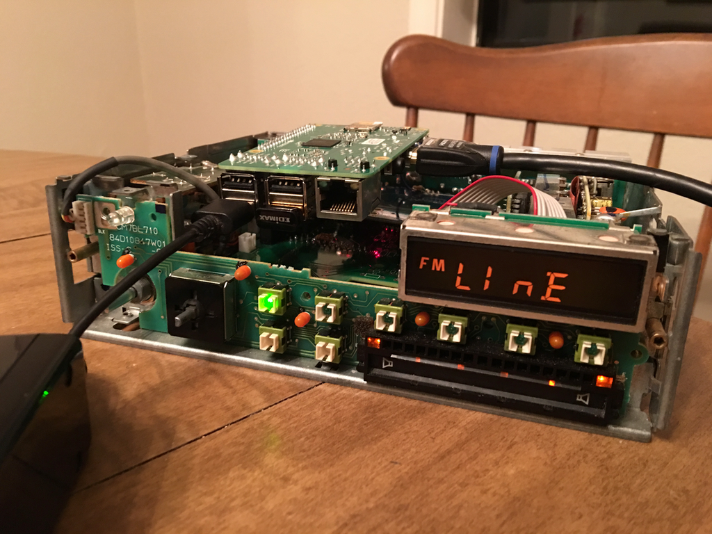
And then here with the red jumpers bringing the radio signal out to the connector. My little jumpers look right at home amongst all the factory rework that had to be done. I'm blown away by that.... rework labor must have been cheap.
Finished up the board the other day and sent it off to be printed, now I just have to wait, then start assembling and validating the HW.
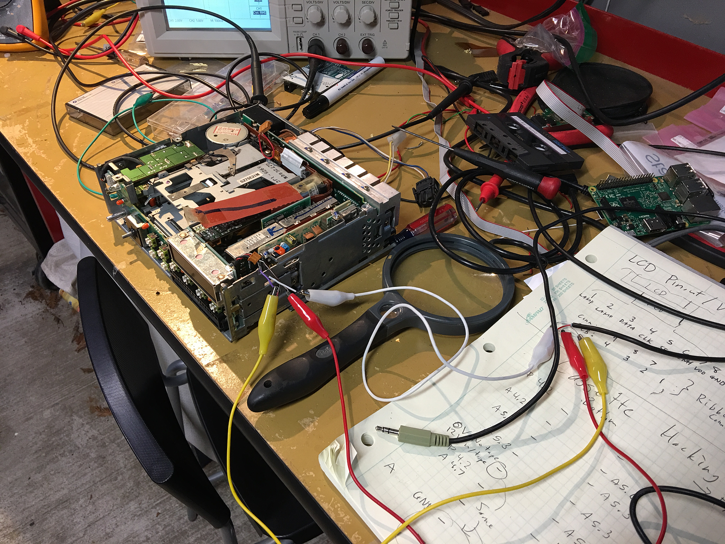
Now that I'm just waiting, I decided to go out last night and work out the details on the simpler approach to this problem that I was mentioning in my previous post. The thing to be figured out was how does the tape deck signal that a tape is in so that the input switches to tape. I put the cassette deck back in the untouched unit (I have two units now, the first is kinda a martyr) and started probing.
I'm sure someone has worked this out before but I don't know if good info is easily available, so here's all you have to do:
The power connector going to the tape deck has the following wires and function:
Green - switched 12V power
Yellow - tape turn on. Drive to 12V to enable tape
Orange - radio turn on. Drive to 12V to enable radio
Red - constant 12V power
Brown - Ground
So the yellow and orange wires seem mutually exclusive, only one is ever driven high. To switch inputs you really just need a SPDT switch between green, yellow, and orange to choose tape or radio.
Here I've connected it so that the tape input is active:
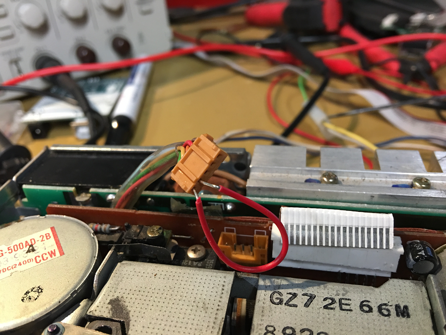
Then I hooked up a 3.5mm cable to the tape input, and all seems to be working.
So a plug-and-play add-on board that gets you BT input is totally possible and not really that difficult to install. Remove the radio, take out the cassette assembly, screw a new board in it's place, connect the two tape deck connectors into the new board, and done. I'm considering making that solution now too, just for the hell of it. Maybe sell them, I don't know. Would anyone be interested?
The last task I hadn't done on the HW hacking side was figuring out where to grab the radio output signal that will become an audio input to the Pi. I needed the post-mix (so the different AM/FM/WB radio modules had already been mixed onto the same stereo bus) but pre-processing like EQ and volume, since I will be handling that myself.
I lucked out with this one. That 3-pin connector I mentioned in my last post that carries the tape deck's output - it turns out, that connector's base on the main board is right next to the pins that contain exactly the stereo signal I want. So I repurposed the tape line-level input to be a radio line-level output by cutting the L/R traces originally running to the connector base, then soldering little jumpers from the connector base to the radio output right next to it. Works like a charm! The signal is a little weak for line-level though so I've added a simple preamp stage to my board to boost it up before leaving the chassis to hook into the USB sound card.
Here, near the bottom center, you can see the two traces I've scratched out. These were leading to the 3-pin connector's base
And then here with the red jumpers bringing the radio signal out to the connector. My little jumpers look right at home amongst all the factory rework that had to be done. I'm blown away by that.... rework labor must have been cheap.
Finished up the board the other day and sent it off to be printed, now I just have to wait, then start assembling and validating the HW.
Now that I'm just waiting, I decided to go out last night and work out the details on the simpler approach to this problem that I was mentioning in my previous post. The thing to be figured out was how does the tape deck signal that a tape is in so that the input switches to tape. I put the cassette deck back in the untouched unit (I have two units now, the first is kinda a martyr) and started probing.
I'm sure someone has worked this out before but I don't know if good info is easily available, so here's all you have to do:
The power connector going to the tape deck has the following wires and function:
Green - switched 12V power
Yellow - tape turn on. Drive to 12V to enable tape
Orange - radio turn on. Drive to 12V to enable radio
Red - constant 12V power
Brown - Ground
So the yellow and orange wires seem mutually exclusive, only one is ever driven high. To switch inputs you really just need a SPDT switch between green, yellow, and orange to choose tape or radio.
Here I've connected it so that the tape input is active:
Then I hooked up a 3.5mm cable to the tape input, and all seems to be working.
So a plug-and-play add-on board that gets you BT input is totally possible and not really that difficult to install. Remove the radio, take out the cassette assembly, screw a new board in it's place, connect the two tape deck connectors into the new board, and done. I'm considering making that solution now too, just for the hell of it. Maybe sell them, I don't know. Would anyone be interested?
Comment