
Well, I've been chipping away at this project for a couple months now but felt as though I should start a thread to document the process (even though it's been done plenty of times already) and to give/receive advice. So here it goes...
First, the back story to the project...
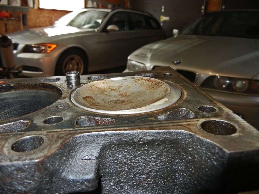
The spark to attempt this build came back in 2010 when this happened...
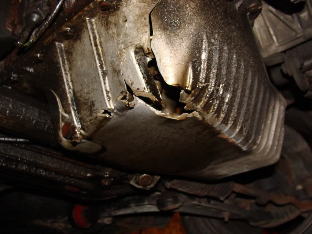
In my hunt for a replacement oil pan I was able to get a whole M20B25 for $100 which is pretty much the going rate for a used oil pan.
So after I finished replacing the oil pan on my car I was left with the rest of the motor and a big question mark about what to do with it. I definitely wasn't going to scrap it. I could have kept it for spare parts or sold the rest of the parts and actually made some profit off of my foray into oil pan smashing but where's the fun in that?
I remembered reading about an M20 2.8L stroker that used a combination of OEM BMW parts, so I did a little bit of research and came across a few build threads (and a few more have popped up between then and now). The combination of parts required is as follows:
- M20B25 cylinder head (885 casting), block and late model (short skirt) pistons... which I already had
- M52B28 crankshaft
- 130mm connecting rods from either the M20B20 or M20B27
- crank spacer for front oil seal
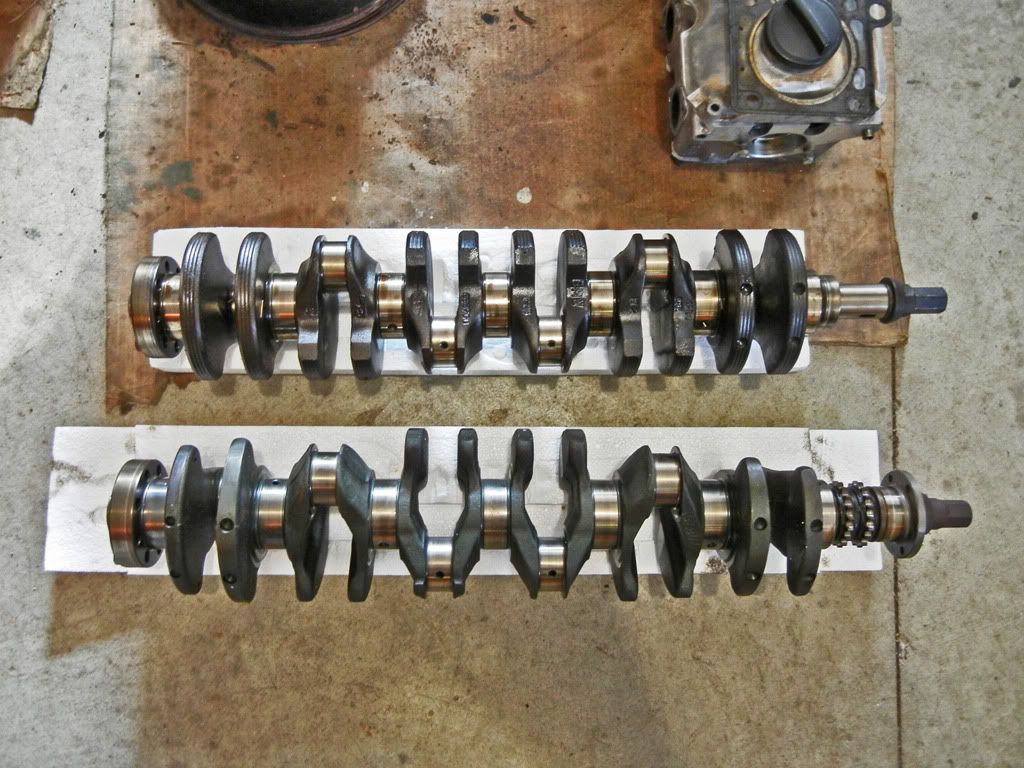
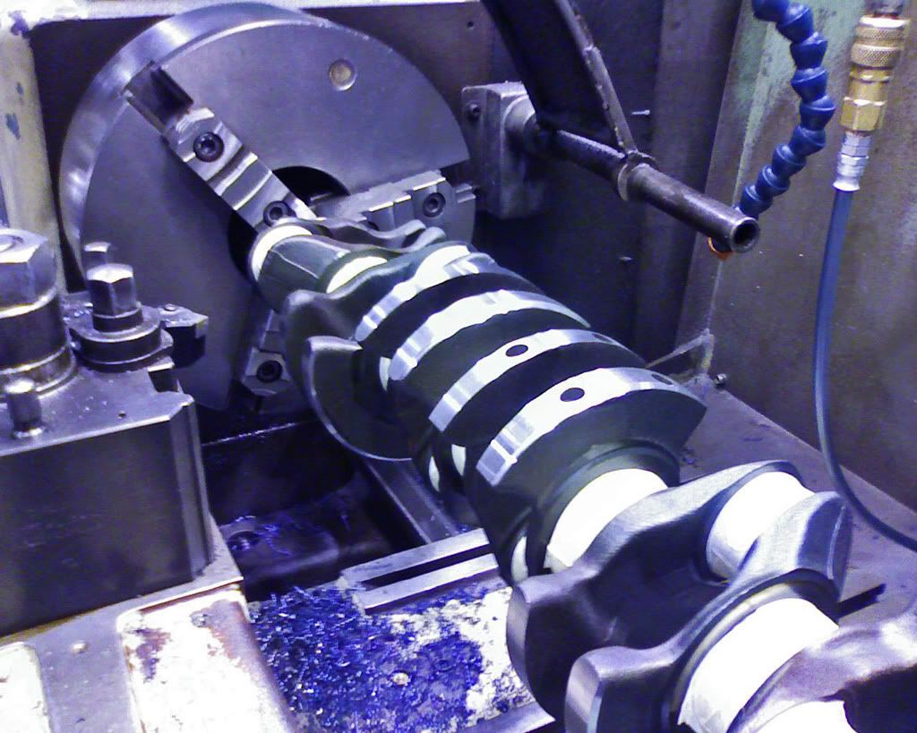
I figured it wouldn't be very hard to find the missing pieces so I stashed the motor away and kept my eye out for the missing pieces. Before Christmas that year I had picked up a 325e motor and stashed it away. Then last year I came across the crank I needed in Kentucky and had it shipped to a relative of mine who happens to live in Kentucky and who happens to come to Canada to visit us once or twice a year... you can see where I was going with that.
Fast forward to this winter. It's my first winter in 5 years that I'm not in school, so with more free time on my hands than I'm use to I mustered up the gumption to dive into this project.
Goals for the project:
- budget stroker = keep cost to a minimum
- make at least as much power as the 2.8L motor that the crank came out of (~190hp) but with my old shitty 2 valve head ;)
- mainly learn about building a motor as this is the first time I've attempted to build a motor of any kind
Performance parts to be added:
- Ireland Engineering heavy duty rockers
- Some sort of performance headers
- Some sort of performance cam
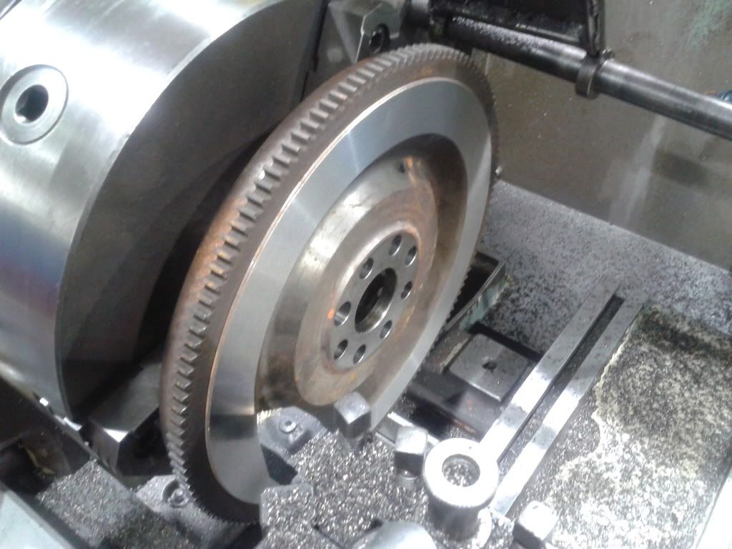
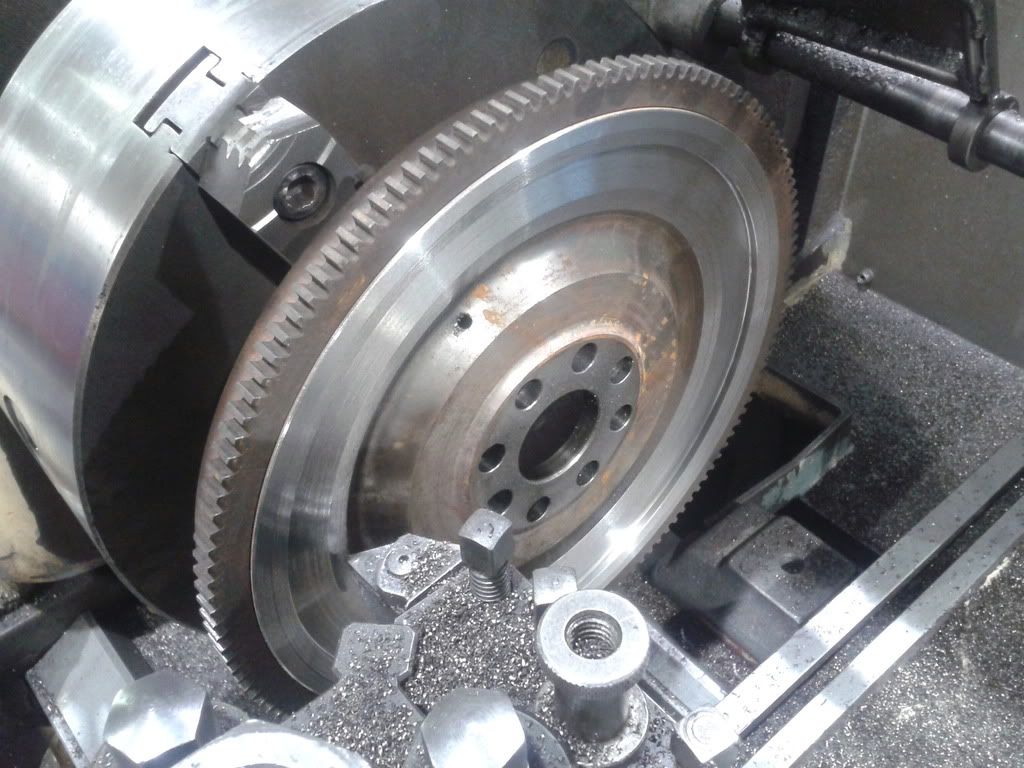
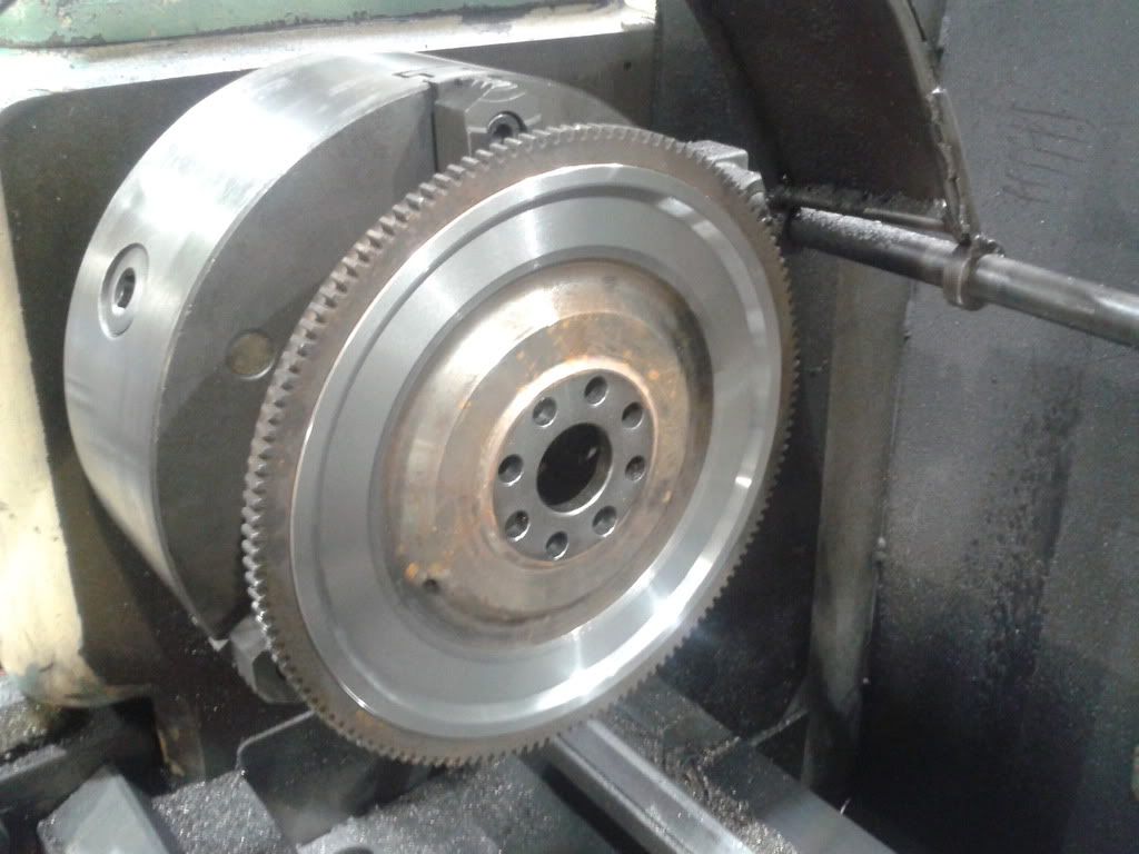
- Lightened flywheel
- Crank scraper
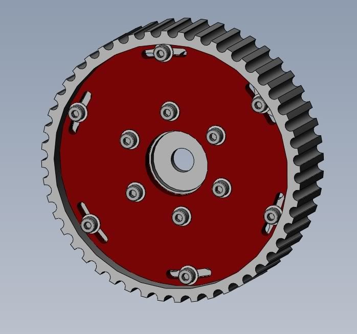
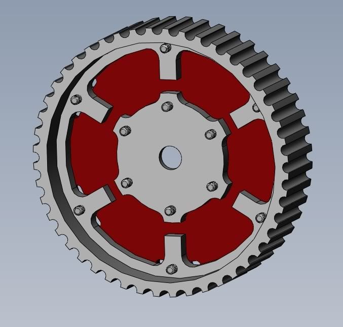
- adjustable cam gear
- DIYPNP engine management
- ITB set-up (this will be another project for after the motor is built and running)
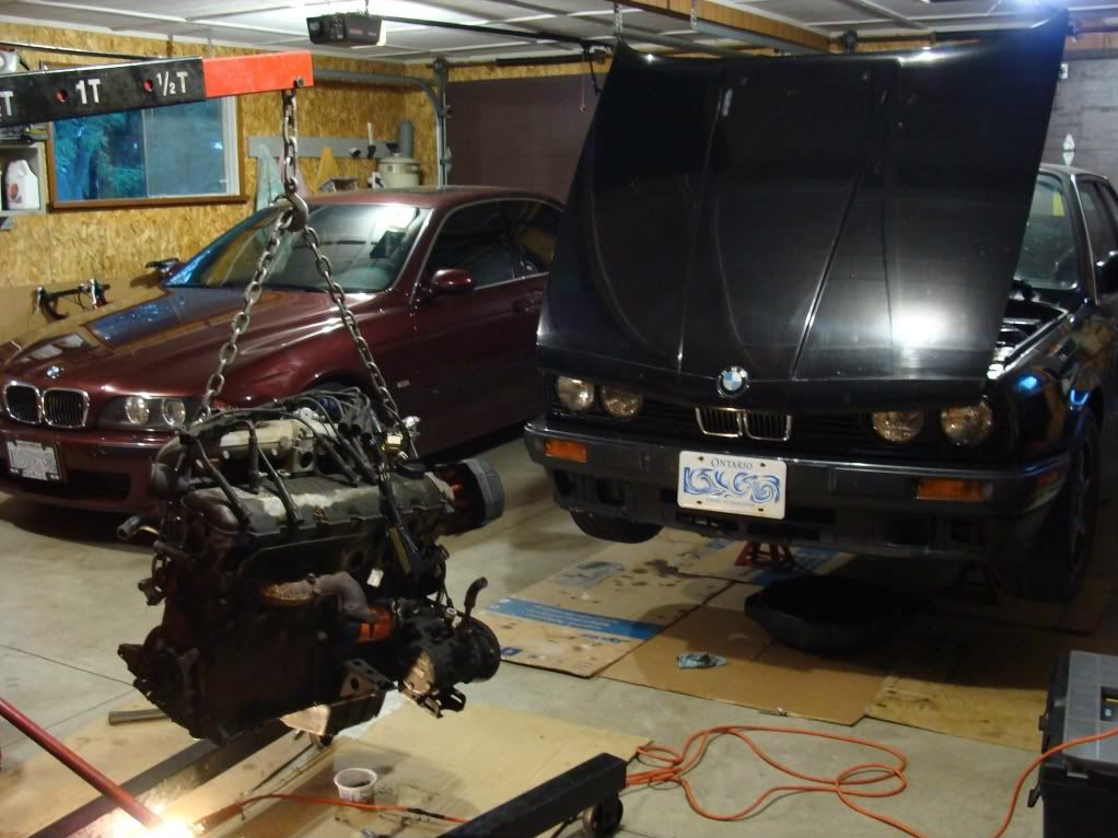
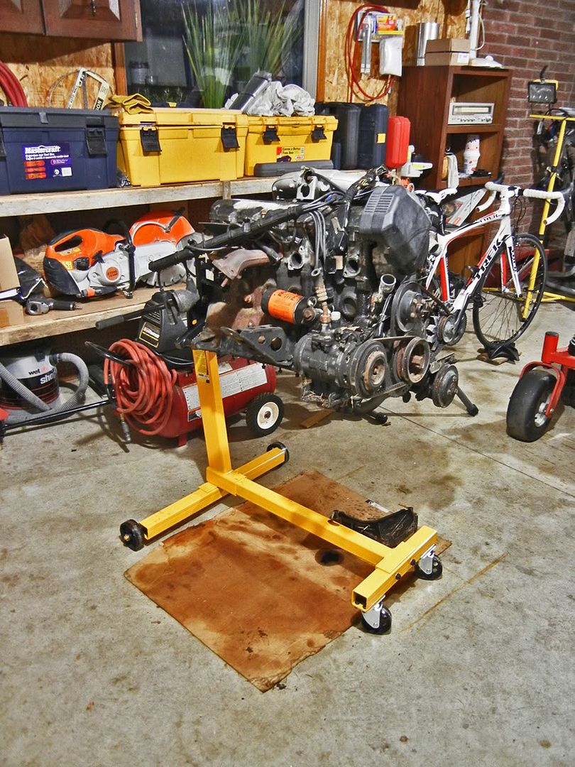
Before the snow hit I bought an engine stand and pulled the motor back into the garage to become a permanent resident for the winter...
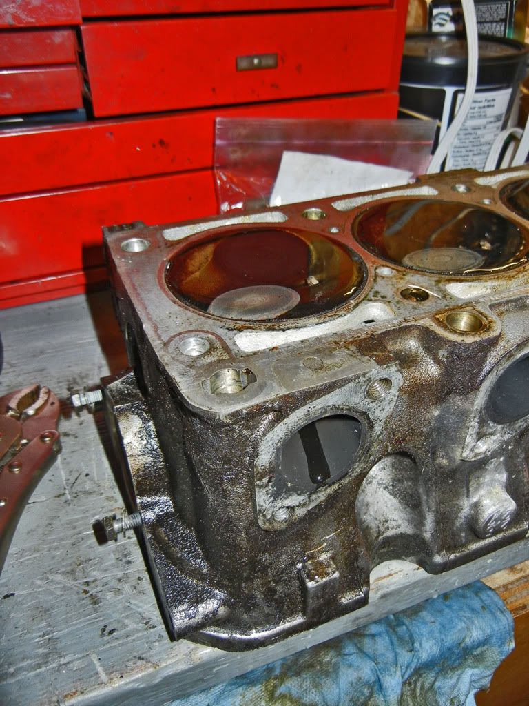
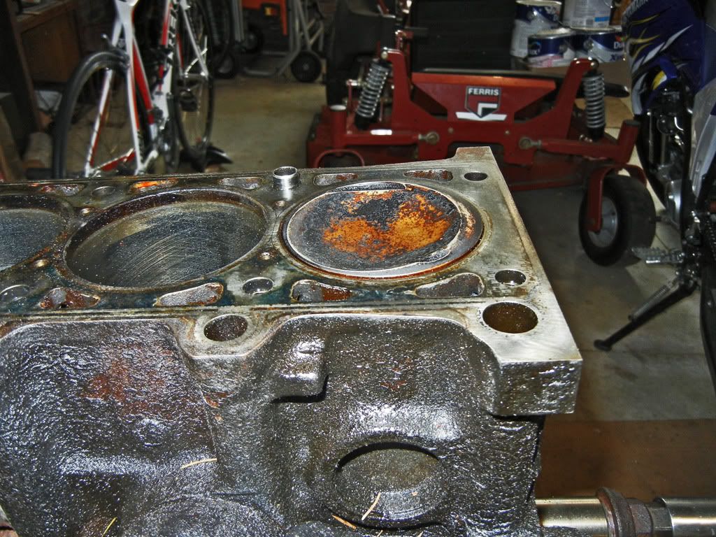
On a side note: After I had pulled the oil pan off that motor I ended up dumping it on a piece of plywood in the bush and covering it with a plastic tarp. It sat there for two years with the crank case open to the atmosphere. I was quite surprised to see when I brought it back into the garage that there was no rust on the cylinder bores at all.
Unfortunately it didn't even cross my mind to take pictures of the motor during the initial tear down but I bagged and tagged all the bits that came off.
Once I had the head disassembled I did an El Ghetto test to see if any of the valves were leaking...

Only the one exhaust valve was leaking...
However the shop that I'm taking the head to for decking said that they'll vacuum check the valve to valve seat seal of all the valves for $20. So I'm going to get them to do that.
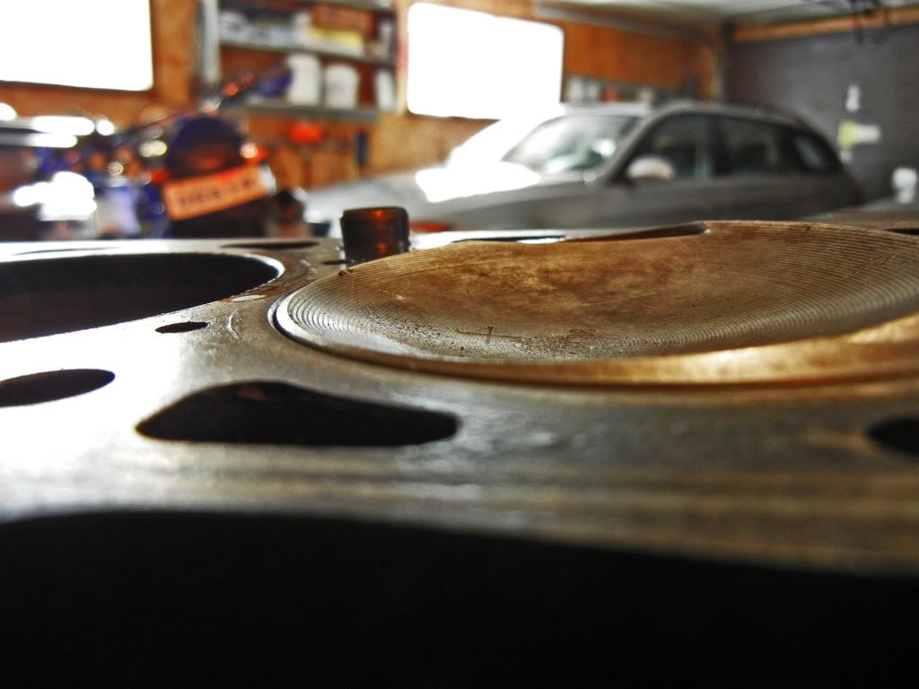
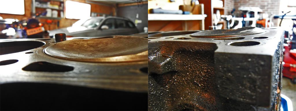
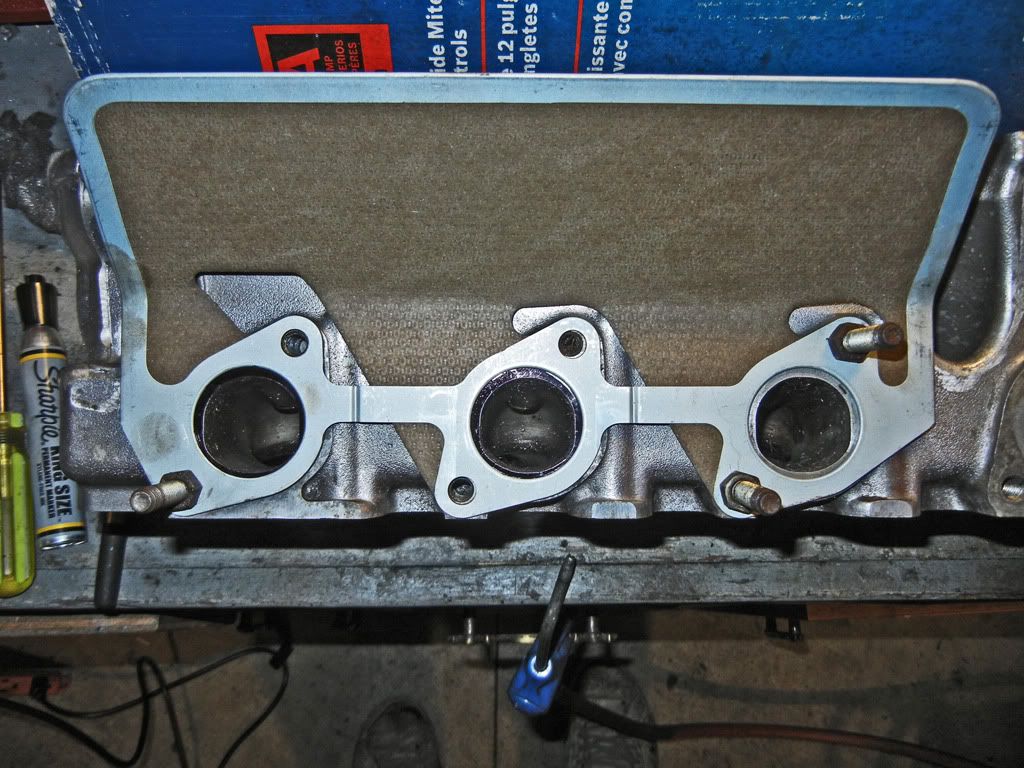
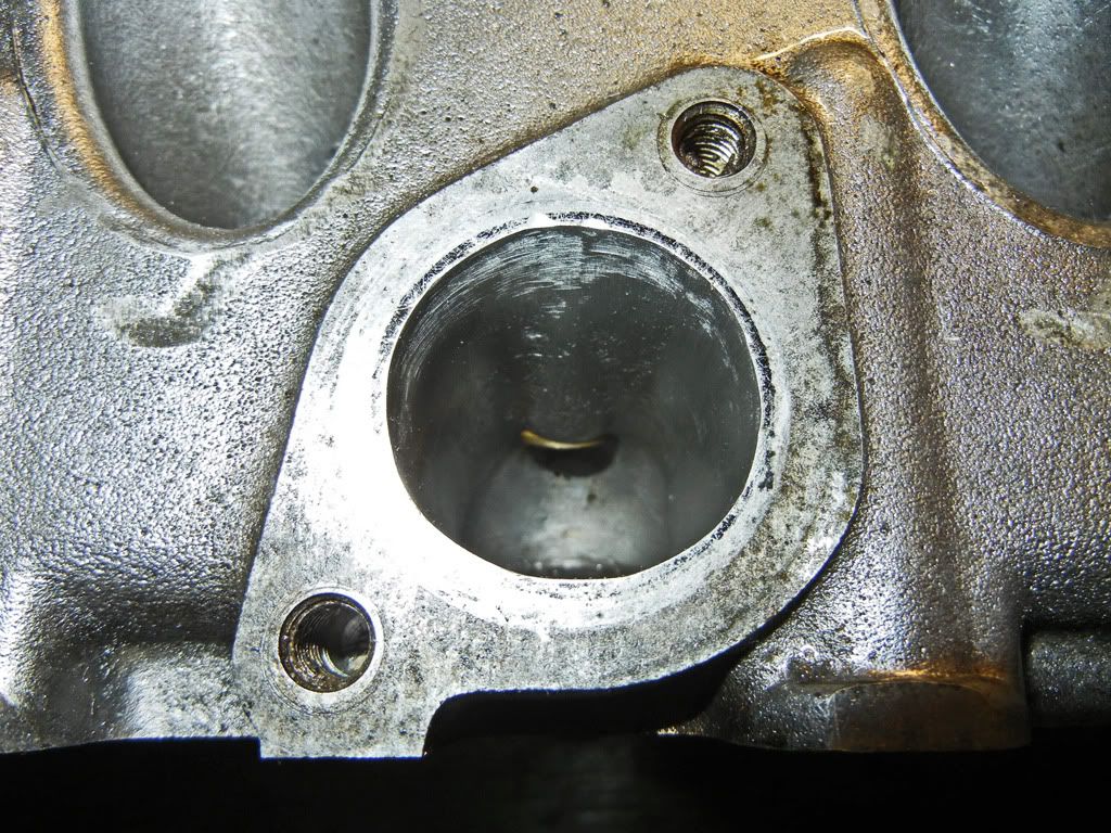
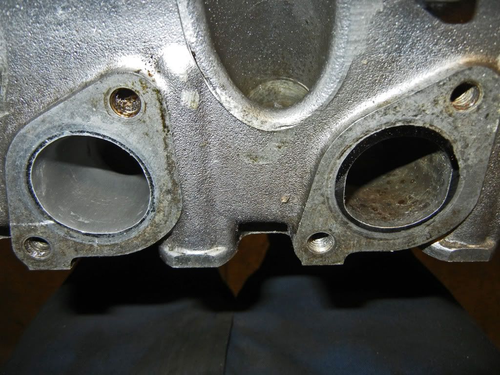
Initial inspection of the head showed quite the step from the exhaust port to the manifold...
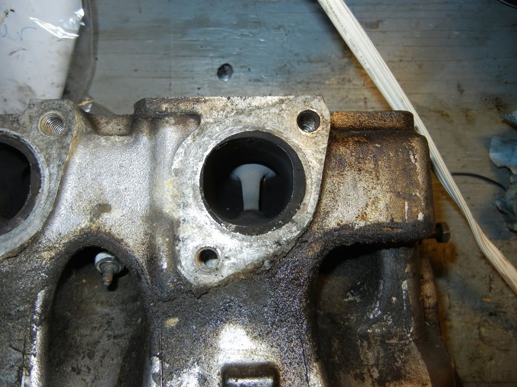
I figured this might be for anti-reversion, but I'd look into it further.
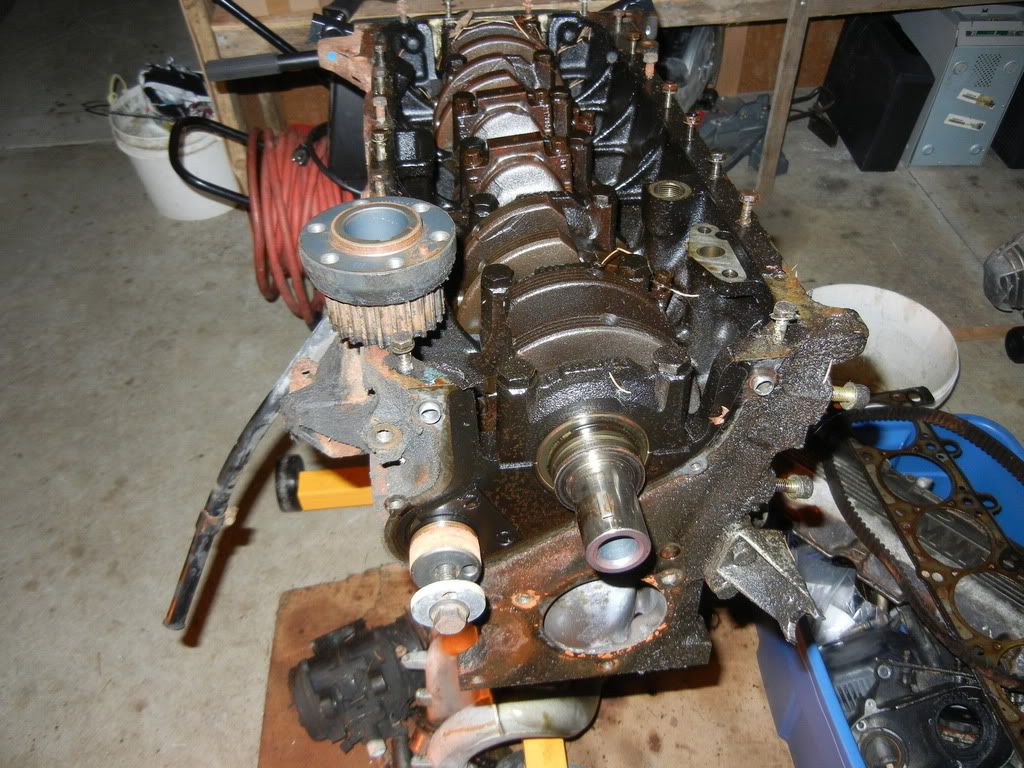
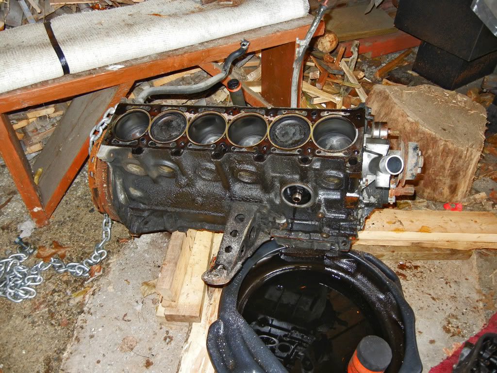
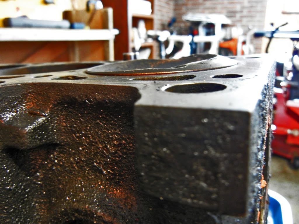
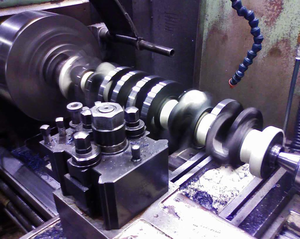
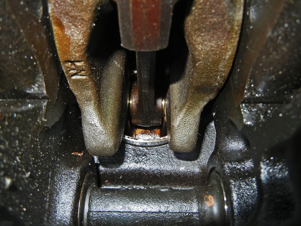
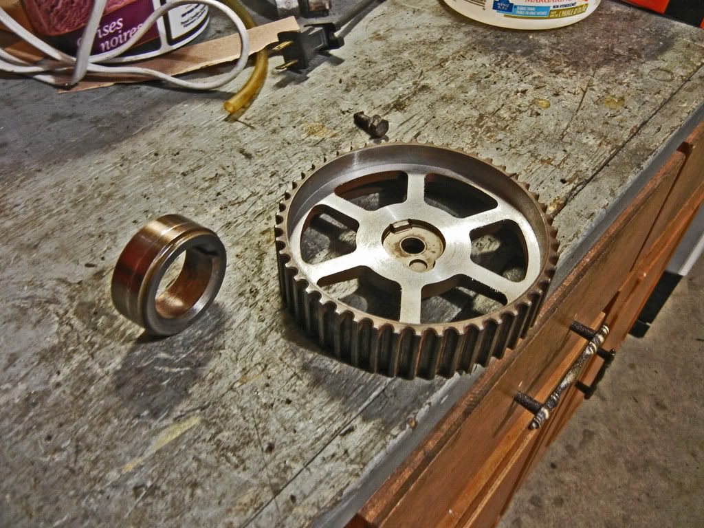
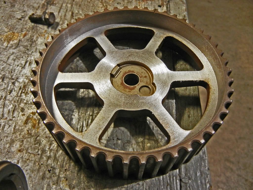
Continuing the tear down, I ripped into the bottom end. Sometimes the timing gear can get seized on when corrosion creeps in between the gear and the crank. I got lucky and mine slid right off
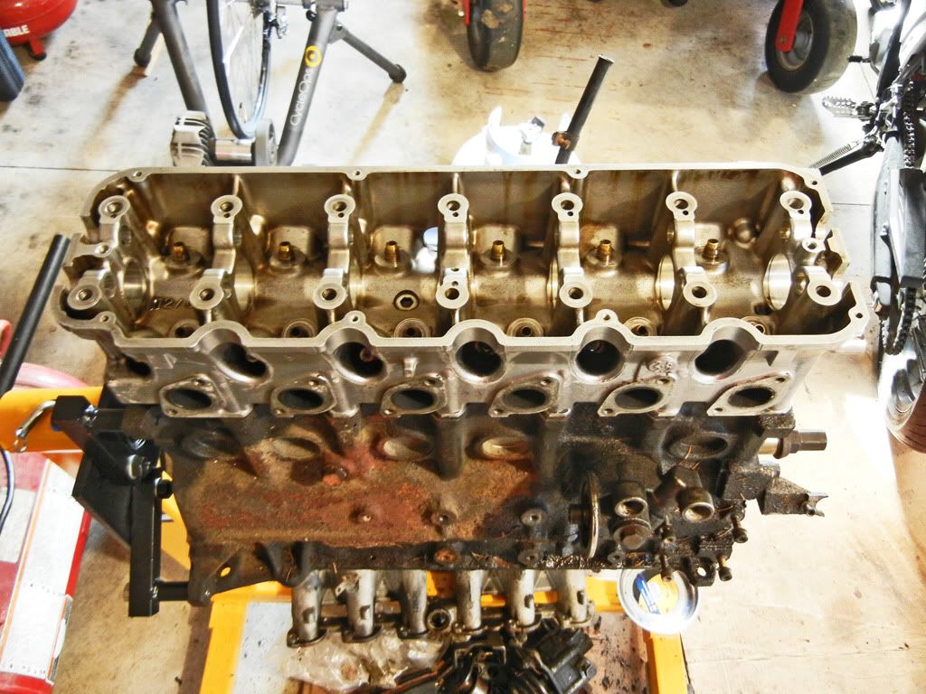
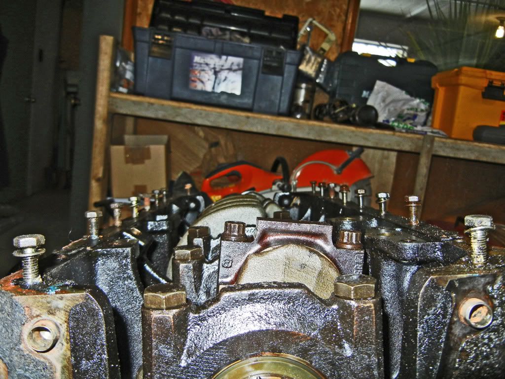
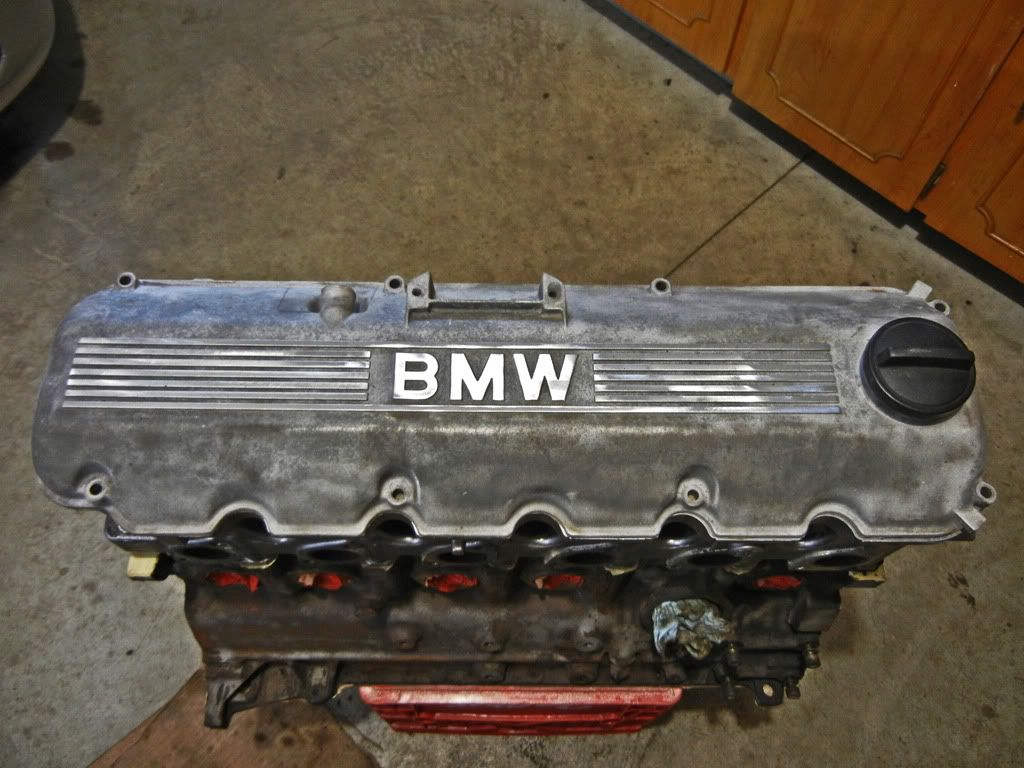
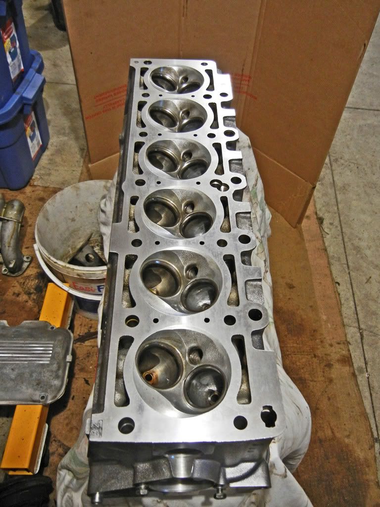
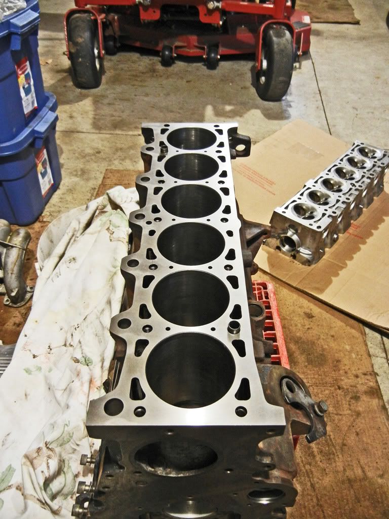
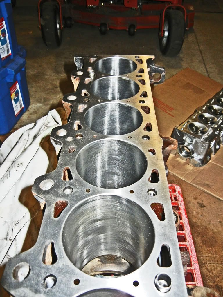
Then I got to cleaning up the head...
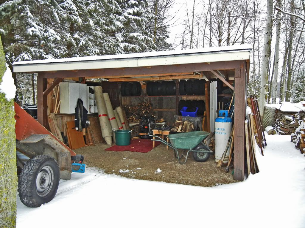
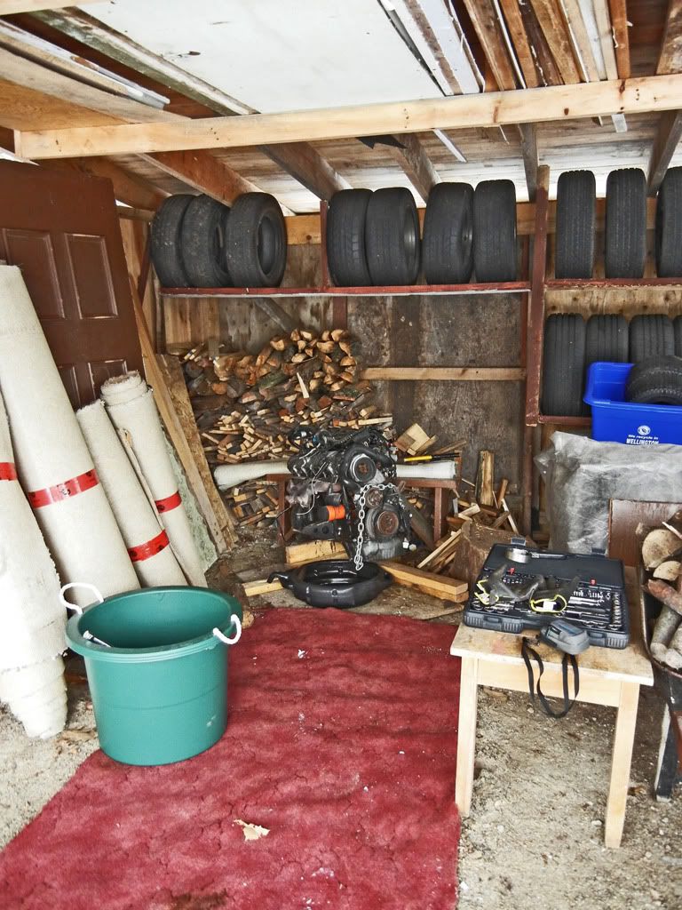
Next I needed the connecting rods out of that 325e motor. When I bought it, I ended up putting it in the back of our wood shed. Not having a convenient way of getting it to the garage I decided to tackle it on one of the not so cold days...
Roll out the red carpet...
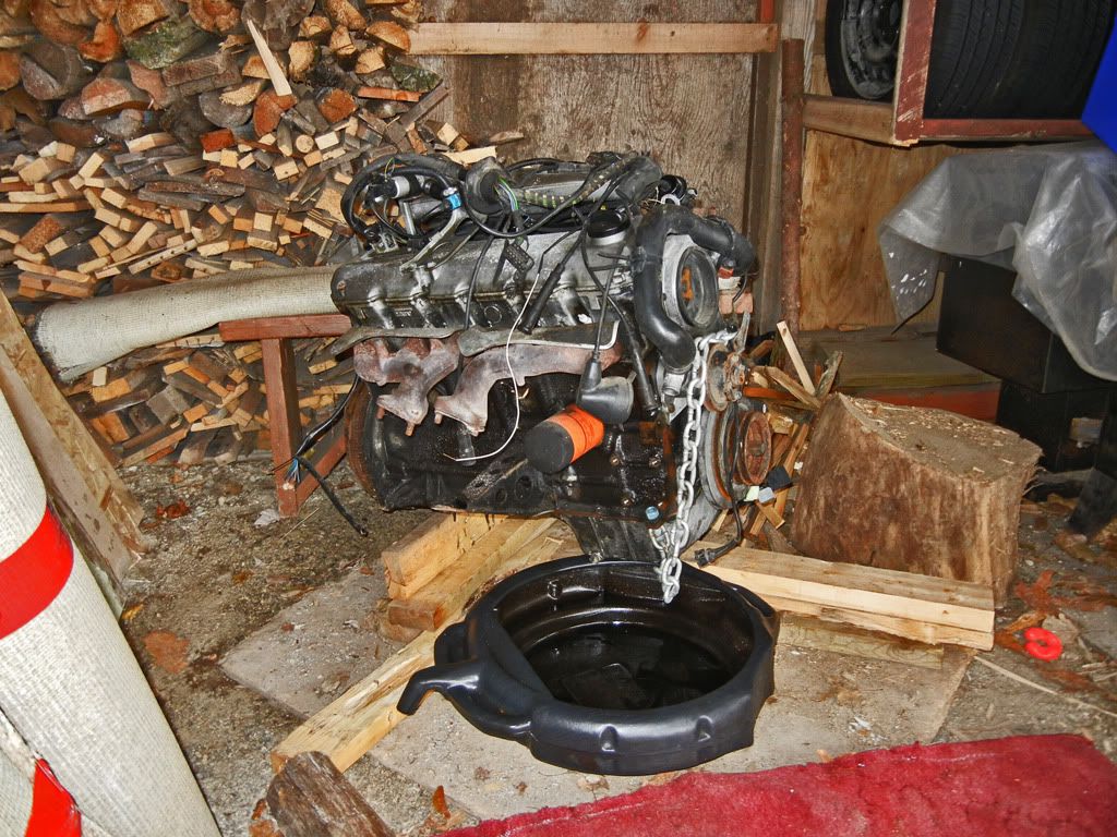
One of the concerns I had was whether or not the oil had been drained out of the motor. Obviously it wasn't... because that would be too easy. I wasn't about to just let the oil drain into the ground, especially when we get our water from a well on the property, so I had to figure out how to get the motor high enough to get a drain pan under it. It turned out to be a delicate process of kicking boards under each end as I lifted each side by hand...
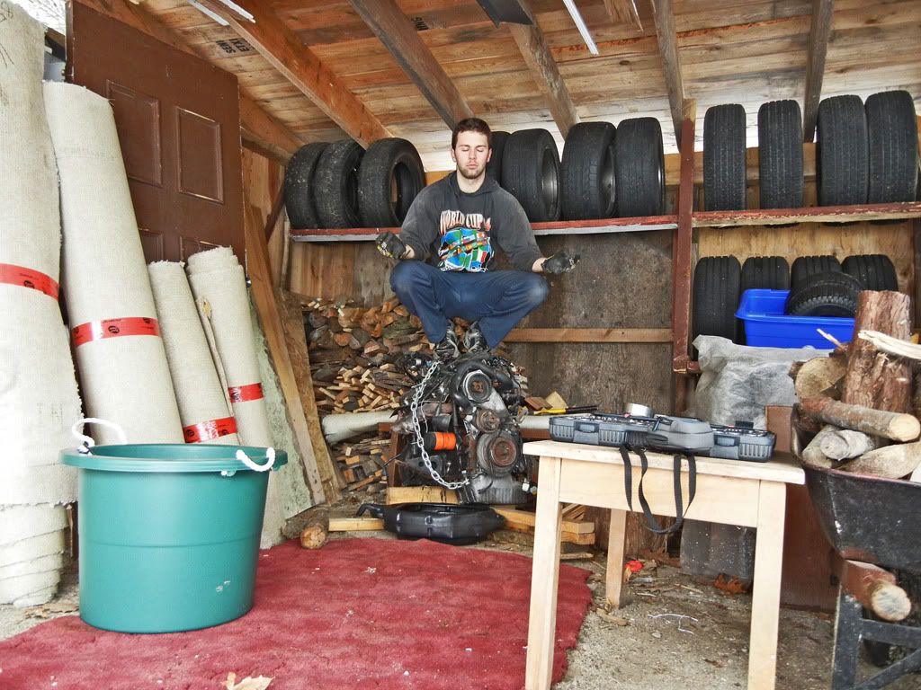
Gassed from muscling the motor around I contemplated... Does tearing apart an eta motor on the ground, in the back of an open woodshed, during the winter just to get a set of connecting rods make me a gear head? I meditated on the thought while the oil drained...
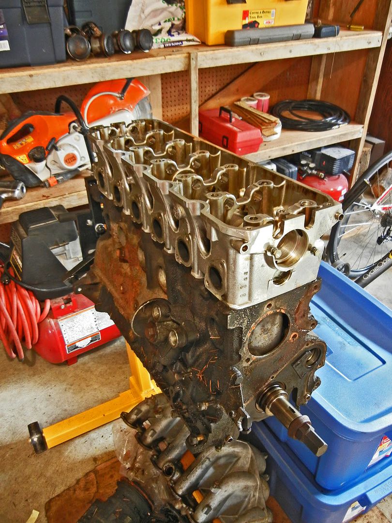
Then I realized that time would have been better spent removing the wiring harness and coolant hoses. Back to work. Shortly after I had the head off...

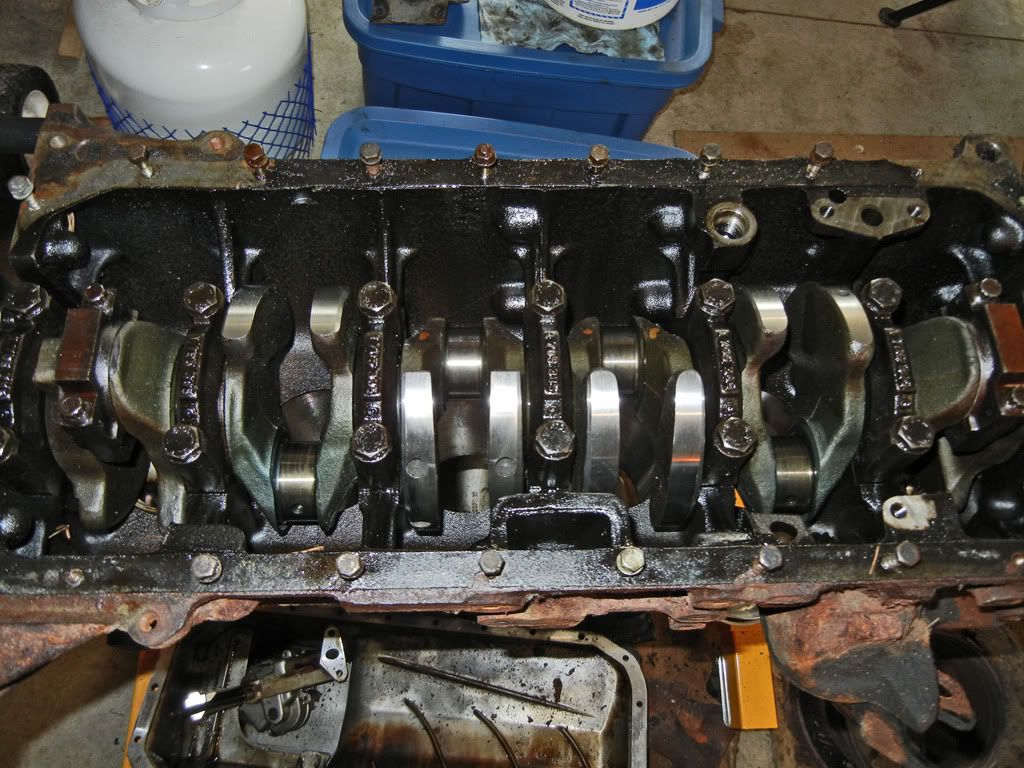
The bores in the motor are in very nice condition which brings me to the question... Does anybody want parts from this motor? With the exception of the rods the rest of the bits are there and I have no need for them any more...
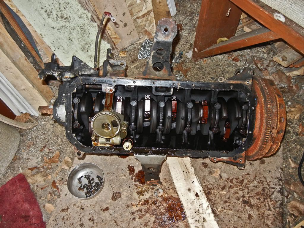
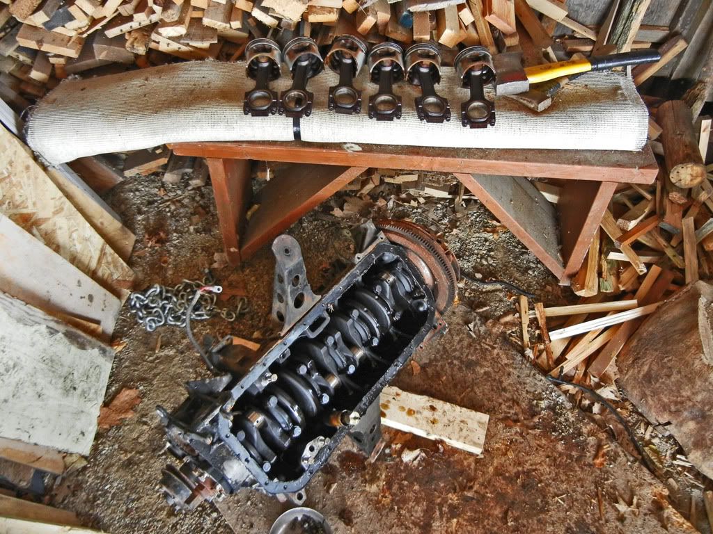
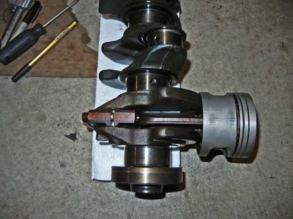
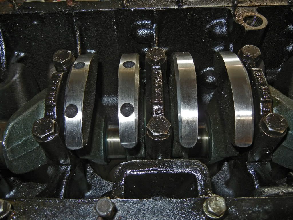
Then I rolled the motor over so I could pull the rod caps and push out the pistons and rods...
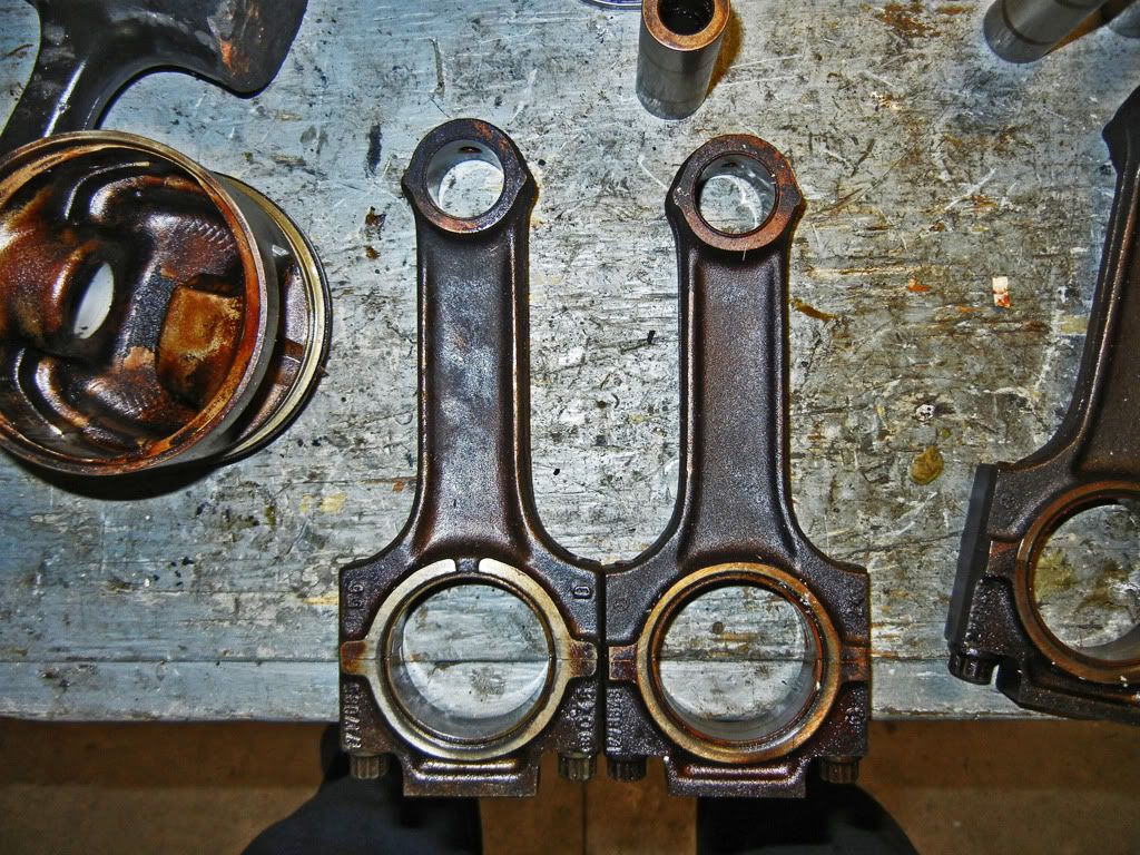
Back in the garage: A comparison between the 135mm B25 rod and short skirt piston and the 130mm B27 rod and piston...

325e flat top vs 325i domed piston...

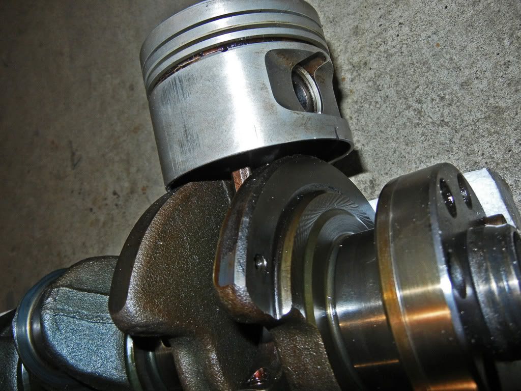
Then I checked the top deck to piston relation at TDC using the stock components for later reference...
The lowest part of the piston (on the left side of the image) comes past the deck ~1.0mm
First, the back story to the project...
The spark to attempt this build came back in 2010 when this happened...
In my hunt for a replacement oil pan I was able to get a whole M20B25 for $100 which is pretty much the going rate for a used oil pan.
So after I finished replacing the oil pan on my car I was left with the rest of the motor and a big question mark about what to do with it. I definitely wasn't going to scrap it. I could have kept it for spare parts or sold the rest of the parts and actually made some profit off of my foray into oil pan smashing but where's the fun in that?
I remembered reading about an M20 2.8L stroker that used a combination of OEM BMW parts, so I did a little bit of research and came across a few build threads (and a few more have popped up between then and now). The combination of parts required is as follows:
- M20B25 cylinder head (885 casting), block and late model (short skirt) pistons... which I already had
- M52B28 crankshaft
- 130mm connecting rods from either the M20B20 or M20B27
- crank spacer for front oil seal
I figured it wouldn't be very hard to find the missing pieces so I stashed the motor away and kept my eye out for the missing pieces. Before Christmas that year I had picked up a 325e motor and stashed it away. Then last year I came across the crank I needed in Kentucky and had it shipped to a relative of mine who happens to live in Kentucky and who happens to come to Canada to visit us once or twice a year... you can see where I was going with that.
Fast forward to this winter. It's my first winter in 5 years that I'm not in school, so with more free time on my hands than I'm use to I mustered up the gumption to dive into this project.
Goals for the project:
- budget stroker = keep cost to a minimum
- make at least as much power as the 2.8L motor that the crank came out of (~190hp) but with my old shitty 2 valve head ;)
- mainly learn about building a motor as this is the first time I've attempted to build a motor of any kind
Performance parts to be added:
- Ireland Engineering heavy duty rockers
- Some sort of performance headers
- Some sort of performance cam
- Lightened flywheel
- Crank scraper
- adjustable cam gear
- DIYPNP engine management
- ITB set-up (this will be another project for after the motor is built and running)
Before the snow hit I bought an engine stand and pulled the motor back into the garage to become a permanent resident for the winter...
On a side note: After I had pulled the oil pan off that motor I ended up dumping it on a piece of plywood in the bush and covering it with a plastic tarp. It sat there for two years with the crank case open to the atmosphere. I was quite surprised to see when I brought it back into the garage that there was no rust on the cylinder bores at all.
Unfortunately it didn't even cross my mind to take pictures of the motor during the initial tear down but I bagged and tagged all the bits that came off.
Once I had the head disassembled I did an El Ghetto test to see if any of the valves were leaking...
Only the one exhaust valve was leaking...
However the shop that I'm taking the head to for decking said that they'll vacuum check the valve to valve seat seal of all the valves for $20. So I'm going to get them to do that.
Initial inspection of the head showed quite the step from the exhaust port to the manifold...
I figured this might be for anti-reversion, but I'd look into it further.
Continuing the tear down, I ripped into the bottom end. Sometimes the timing gear can get seized on when corrosion creeps in between the gear and the crank. I got lucky and mine slid right off
Then I got to cleaning up the head...
Next I needed the connecting rods out of that 325e motor. When I bought it, I ended up putting it in the back of our wood shed. Not having a convenient way of getting it to the garage I decided to tackle it on one of the not so cold days...
Roll out the red carpet...
One of the concerns I had was whether or not the oil had been drained out of the motor. Obviously it wasn't... because that would be too easy. I wasn't about to just let the oil drain into the ground, especially when we get our water from a well on the property, so I had to figure out how to get the motor high enough to get a drain pan under it. It turned out to be a delicate process of kicking boards under each end as I lifted each side by hand...
Gassed from muscling the motor around I contemplated... Does tearing apart an eta motor on the ground, in the back of an open woodshed, during the winter just to get a set of connecting rods make me a gear head? I meditated on the thought while the oil drained...
Then I realized that time would have been better spent removing the wiring harness and coolant hoses. Back to work. Shortly after I had the head off...
The bores in the motor are in very nice condition which brings me to the question... Does anybody want parts from this motor? With the exception of the rods the rest of the bits are there and I have no need for them any more...
Then I rolled the motor over so I could pull the rod caps and push out the pistons and rods...
Back in the garage: A comparison between the 135mm B25 rod and short skirt piston and the 130mm B27 rod and piston...
325e flat top vs 325i domed piston...
Then I checked the top deck to piston relation at TDC using the stock components for later reference...
The lowest part of the piston (on the left side of the image) comes past the deck ~1.0mm


Comment