
-
Try this to make sure all the harness stuff is correct.Originally posted by jlevie View Post
Here is the DME pinout: https://docs.google.com/file/d/0B97_...zg3/edit?hl=enLeave a comment:
-
I had a similar issue when I used the m20 harness. Never fully figured it out. However, I swapped over to the b35 harness and it ran like a champ.Leave a comment:
-
I ran with no o2 for a month in my e30 m30b35 and used the m20b25 harness and it ran without a hickup. If its not intake leaks I would suspect that youre getting a wrong signal to the ecu because of a faulty maf, tps, etc.
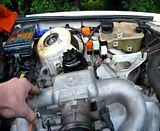
My brake booster set up...
Leave a comment:
-
^Yeah i figured that out, i was just stumped since this motor came out of my bro's e34....that is the least of my worries now tho, I need this thing to run right!Leave a comment:
-
Corrected my vacuum lines and it still runs the same. While running I unplugged the tps, ran the same. Also while running I unplugged the miller maf sensor, and there was no change...Leave a comment:
-
after searching on here all evening, i believe I have one of the vacuum lines on wrong.
Also wondering where to hook up the brake booster hose??...Leave a comment:
-
Needs throttle to start, will run while barely on throttle, if more throttle is given it surges...
Leave a comment:
-
Okay, so I did find a small vacuum hose unhooked (went to charcoal canister), and tighten the grounds and sanded some paint off the ground on the motor mount. It still runs like crap and surges. There is no alternator hooked up and some of the injectors are turned so the shorter wires on the m20 harness would reach ( i dont know if that affects anything). Currently trying to get a video of it running to load..Leave a comment:
-
Your grounds should be fine then. Did you sand paint off the mount so it is metal to metal? O2 sensor would only cause it to run closed loop and a bit on the rich side. I would double and triple check vacuum.Leave a comment:
-
Which grounds? The engine is grounded with a new cable from motor mount to body. Im pretty sure the harness ground is secured but I will make sure tomorrow. Should no o2 sensor cause anything like this?Leave a comment:
Leave a comment: