-
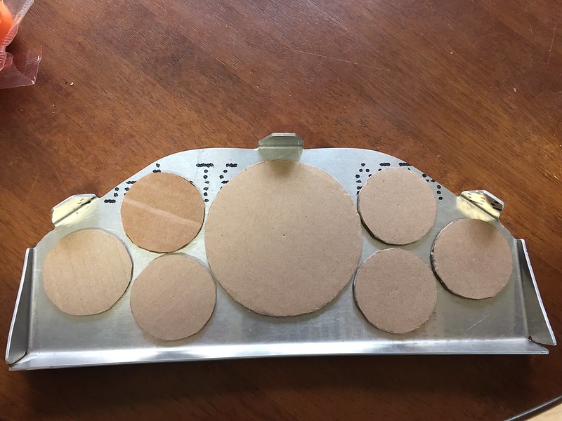
I knew I wanted to have a lot of gauges to keep an eye on everything but I also wanted to keep a clean look to the interior. That meant A-pillar pods, dash pods, center console pods, etc were out of the question for me. Massive Brakes in Canada used to sell a DTM gauge panel with laser cutouts and anodized finish. Really, really nice panels. Only problem was the cutouts were not customizable. To get the gauge cutouts I wanted he would have to do a minimum batch size of 20 panels. No chance I was going to pay for that! Anyway, I showed one of the metal smiths at work what I was trying to replicate and he whipped this up for me by hand in under an hour. It’s made of 6061 aluminum. Nice and beefy. I cut out cardboard to simulate the gauge sizes to make sure everything would fit. Tight, but it works.
 E30 Build by Jason H, on Flickr
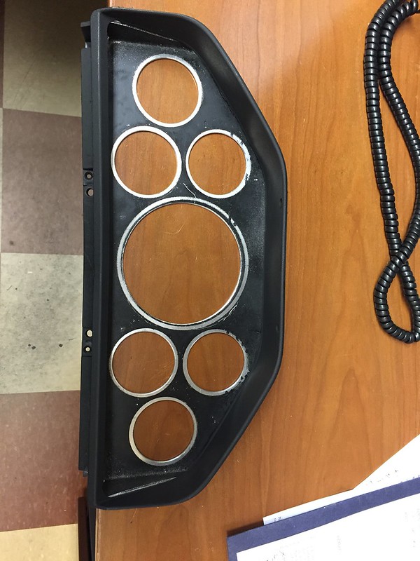
At work we have a laser cutter for softer material. I gave the guys the outer dimensions of my gauges and they cut me some nice rings out of thin plastic so I could lay out the panel before cutting. I drew some grid lines to get everything symmetrical and then lightly dusted the panel with some spray paint to show where the holes needed to be made.
 E30 Build by Jason H, on Flickr
 E30 Build by Jason H, on Flickr
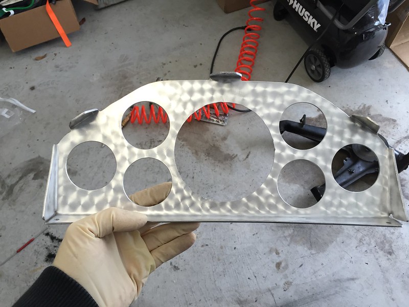
Just messing around I put a cool pattern on the panel with a dremel with a soft stainless wire brush attachment. Ultimately I knew I would have it powdercoated though.
 E30 Build by Jason H, on Flickr
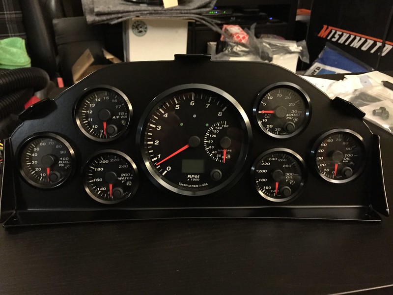
And here’s the finished product after powdercoating.
 E30 Build by Jason H, on Flickr
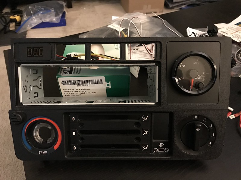
Notice there’s no fuel level gauge. I used the OBC spot on the radio panel to install my fuel level gauge along with a voltmeter in the upper left button opening.
 E30 Build by Jason H, on Flickr
Leave a comment:
-
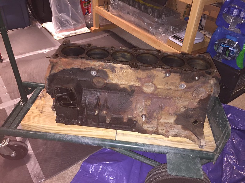
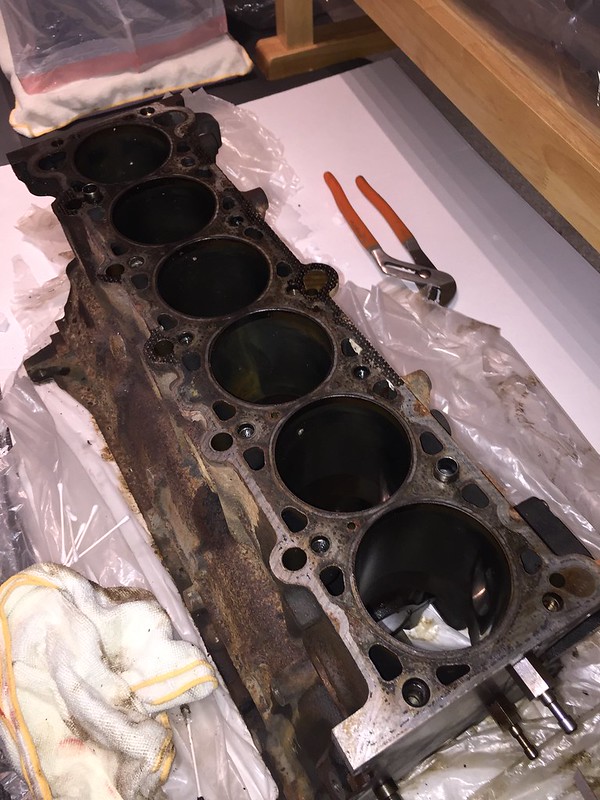
I decided an M52 block would be my best bet to not killing head gaskets since the cylinder walls would be thicker with the smaller bore and allow more head gasket sealing area. I picked up a well used block on eBay and when it showed up it was a rust bucket.
 E30 Build by Jason H, on Flickr
 E30 Build by Jason H, on Flickr
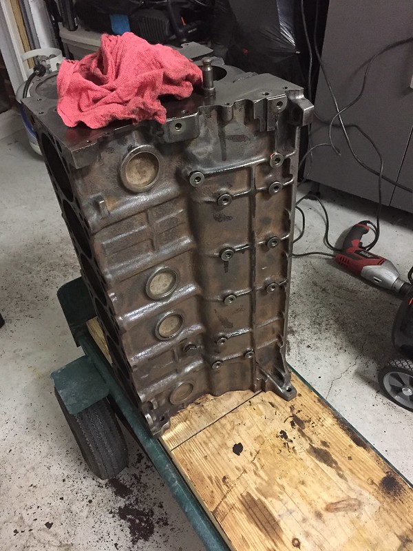
I got to work with a drill and a wire wheel and an hour later it was looking slightly more presentable.
 E30 Build by Jason H, on Flickr
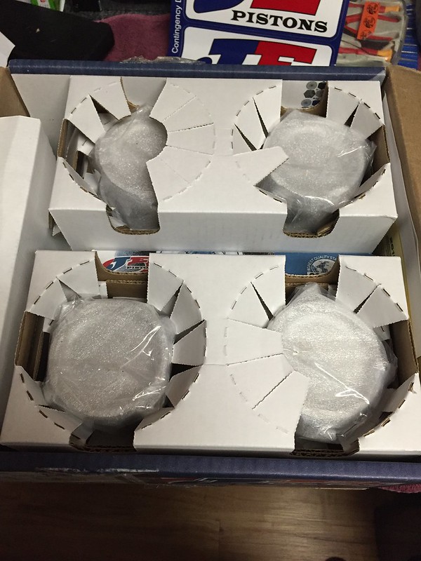
About this time my custom JE pistons arrived. They were built to provide 8.5:1 compression and have the correct pin height to use an S52 crankshaft (89.6mm stroke) and stock sized rods (135mm). I picked a few different options for ring groove upgrades, special coatings, heavy duty wrist pins, etc. Honestly can’t remember all of it but I do remember they were EXPENSIVE. I ordered them from Top End Performance out in California and they showed up within a month or so from JE. I love pretty machined things.
 E30 Build by Jason H, on Flickr
 E30 Build by Jason H, on Flickr
 E30 Build by Jason H, on Flickr
With everything for the block in-hand I headed down to Korman Motorworks in North Carolina to have them do all the machining on the block. They checked my mains and decided I didn’t need an align hone (most of these iron blocks don’t). I had them bore it out from 84mm to 84.5mm to match my pistons and they finished up with a torque plate hone and then slapped some paint on the block to pretty it up. More on the engine build later…Last edited by jph; 09-19-2019, 09:08 AM.Leave a comment:
-
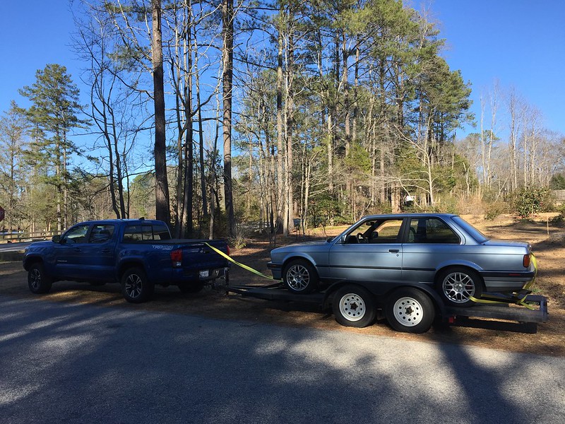
So I guess I’ll start from the beginning. I had a super clean alpine white ’89 sedan that I was planning to do an S52 swap into. I began gathering some parts for the swap and somewhere along the way decided to go turbo S52. Of course this would necessitate larger tires and beefed up everything. I couldn’t bring myself to go cutting up such a clean sedan when a coupe was more what I had in mind for this all-out build. I sold the sedan and found a very clean ‘90 coupe with about 300k miles on it about 5 hours away. I borrowed a trailer from a friend and headed down to North Carolina from Virginia to pick it up. When I arrived it was pretty much what I expected: terrible re-spray with runs in the paint, worn out interior, reeked horribly of cigarette smoke…but drove decently. Ok, I figured this would work since I was planning a shell-up resto anyway. Away I went with the car.
 E30 Build by Jason H, on Flickr
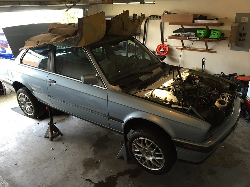
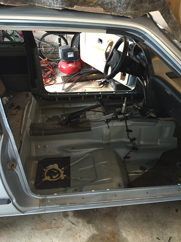
As soon as I got it home I began stripping it down. Pulled everything out of the car except the suspension and wheels to keep it a roller for now.
 E30 Build by Jason H, on Flickr
 E30 Build by Jason H, on Flickr
 E30 Build by Jason H, on Flickr
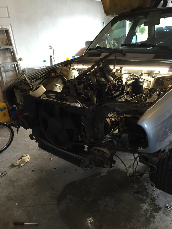 E30 Build by Jason H, on Flickr
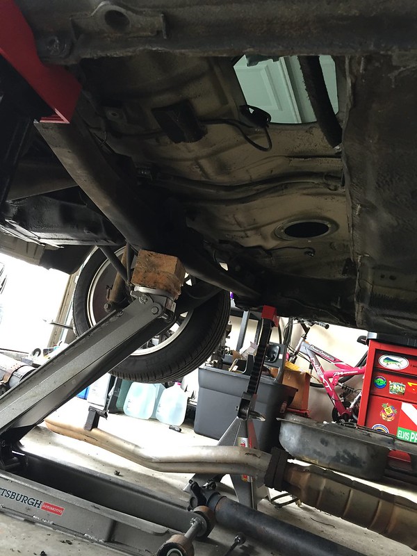 E30 Build by Jason H, on Flickr
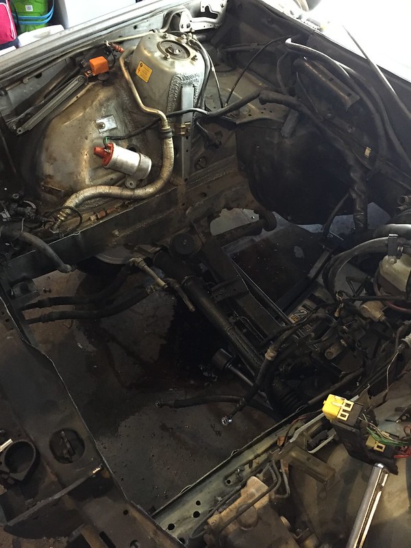 E30 Build by Jason H, on Flickr
I also decided now would be a good time to remove all the engine bay brackets I wouldn’t need anymore.
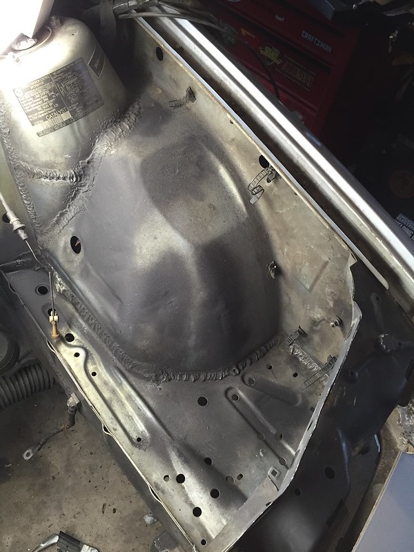 E30 Build by Jason H, on Flickr
Time to load it back on the trailer and head out to my dad’s place a few hours away. The plan was to remove the rear cross member and diff mount and fabricate a stronger cross member that would also allow a large case 210mm diff to be installed. Vorshlag did something similar on the GRM Challenge car a few years back, but they used a medium case diff. Other than that there wasn’t much of a trail blazed for this work. I used pictures they had posted to get me started…
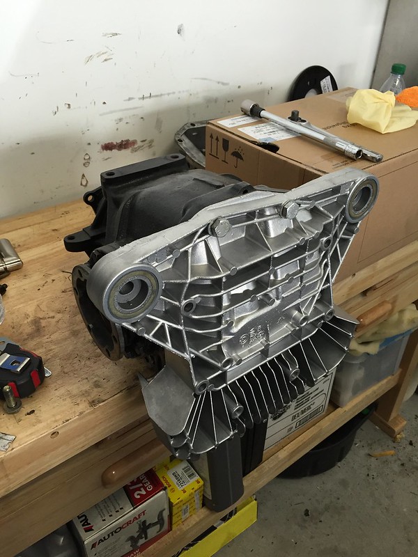
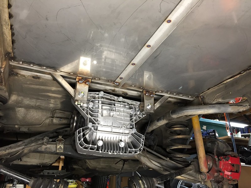
Here’s the diff. It’s a 3.25 LSD out of an ’86 Euro M535i. Pretty hard to come by these suckers, but I found one across the country and had it shipped over. All large case diffs share the same rear housing bolt pattern and I decided an E46 M3 rear cover would be good since it has dual mounts and a massive amount of cooling fins. It also looks badass. I gotta tell you this thing is massive. Weighs in north of 100 pounds.
 E30 Build by Jason H, on Flickr
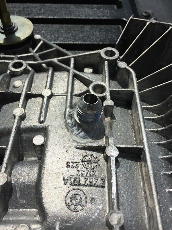
But wait, I realized the E28 had its diff fill plug on the rear cover. Using the E46 M3 cover I was left with just a drain plug on the diff housing itself. After some back and forth I decided to have a -8 AN bung welded to the cover to allow me to service the diff in the future.
 E30 Build by Jason H, on Flickr
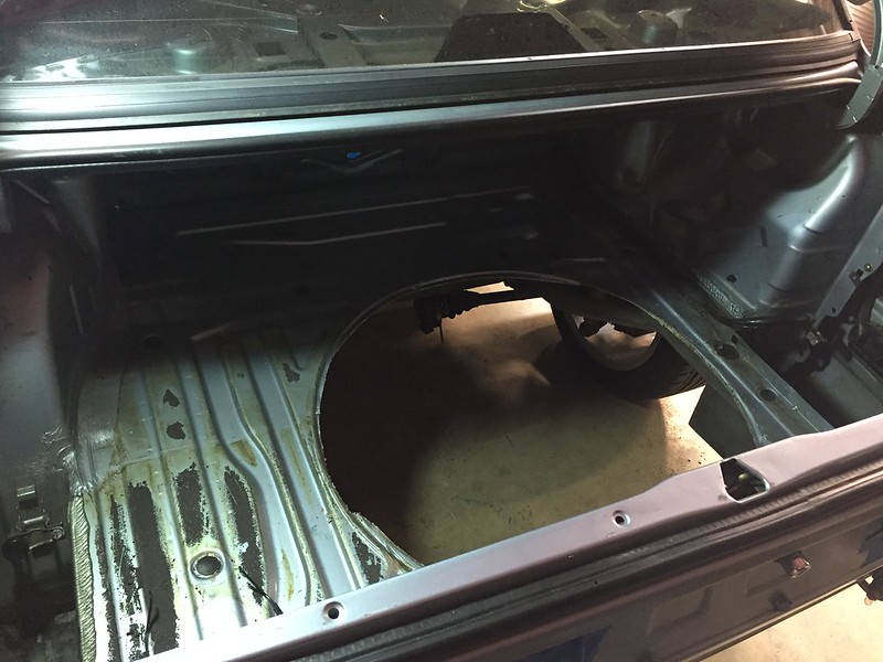
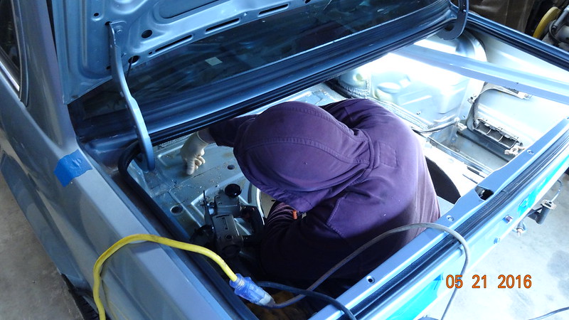
So here I am with a diff and a dream. Time to get to work fitting it up. My dad and I tackled this job over the course of two weekends in May 2016. We started by cutting out the spare tire well and most of the trunk floor to give is access to the cross member.
 E30 Build by Jason H, on Flickr
 E30 Build by Jason H, on Flickr
Once that was out of the way we started removing the cross member.
 E30 Build by Jason H, on Flickr
Where the cross member originally tied into the frame on both sides of the trunk we used 3/16” stainless angle to create a mounting pad for the new cross member.
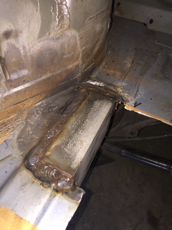 E30 Build by Jason H, on Flickr
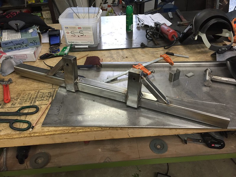
The new cross member would be made of 2”x2” 3/16” thick stainless square tube. Here is the tube stock and a few pictures of us fitting everything up before welding. The vertical standoffs where the diff will be mounted are 1.5”x2” 1/8” thick stainless rectangular tube stock. We notched them to wrap around the crossmember to give more area to weld them on. We also cut holes in them and welded in round stock to keep the diff bolts from crushing them when it was tightened down.
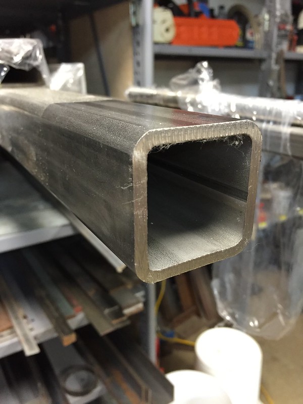 E30 Build by Jason H, on Flickr
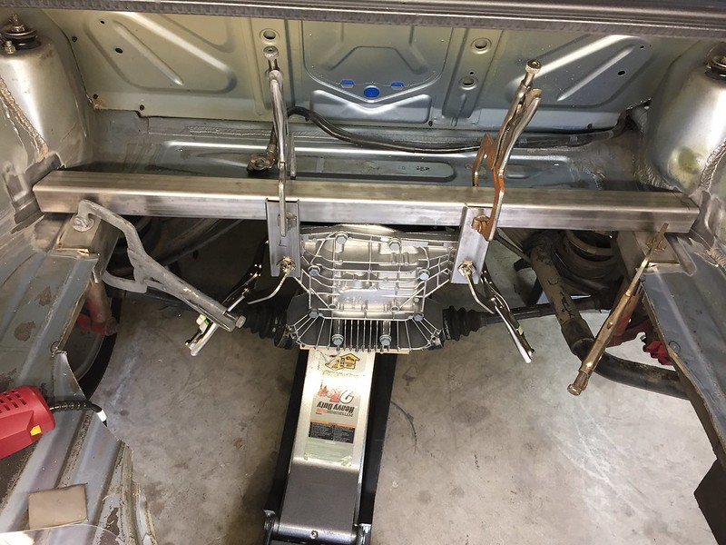 E30 Build by Jason H, on Flickr
My dad handled all the welding on this job. Here he is going to town with the MIG.
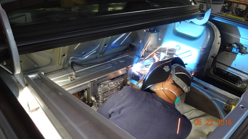 E30 Build by Jason H, on Flickr
Once we had everything welded in place on the cross member we pulled it back out of the car and added a pair of angled braces to the vertical standoffs.
 E30 Build by Jason H, on Flickr
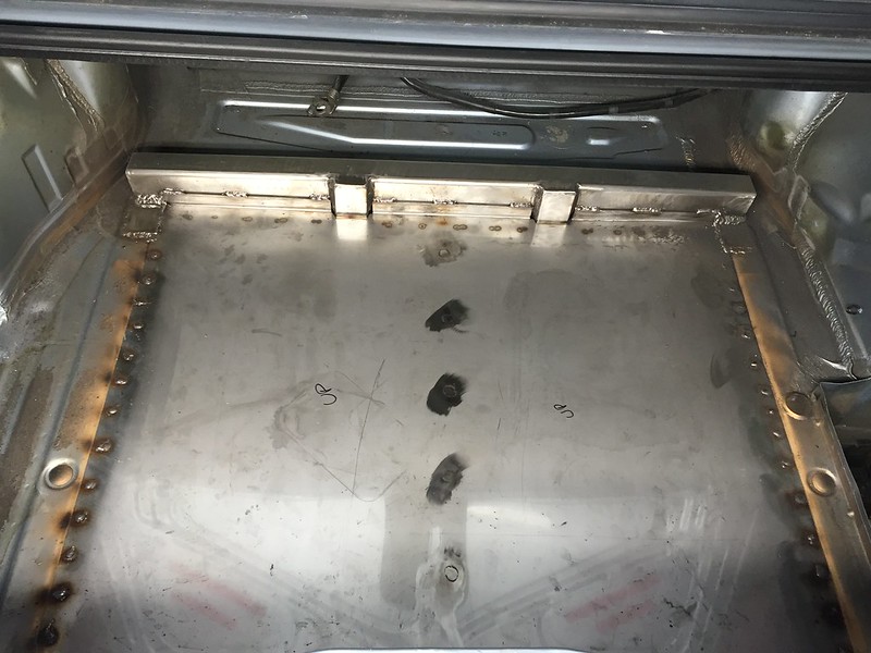
Finally we welded the cross member to the stainless angles already attached to the frame rails. For the floor we used 14 gauge stainless steel with a center support angle tied to the cross member and bolted to the rear of the car to keep the floor nice and solid. We left around 1” of original trunk floor around the perimeter and drilled holes in the stainless sheet every couple of inches to plug weld it solidly to the car. Here’s the final result.
 E30 Build by Jason H, on Flickr
 E30 Build by Jason H, on Flickr
Leave a comment:
-
-
Hey thanks for all the love everyone!
It's good to get some feedback from someone with lots of hands on experience with this manifold. I hope to be done with my new wastegate routing this weekend and if it doesn't hold boost I'll consider the turbine housing swap as a next step. I was hoping you wouldn't say pull th manifold to put the sensor in. At that point I'd just try an entirely new wastegate setup.
It's an M52 block bored to 84.5mm, S52 crank, Molnar rods, custom JE pistons, CES cut ring head gasket (stock thickness).
I plan to cover the motor build with pictures and more detail in a later post. Don't boost 24 psi on a stock motor!!Leave a comment:
-
Sweet car! Love the color. Is that an m50? Stock internals? I'm currently (re)building an m50nv with a .140MLS and ARPs +HX35 and would love to see those numbers..Leave a comment:
-
Awesome build! Gotta agree with Simon, the MTECH bumper without all the extras looks really good on your car!Leave a comment:
-
The 24v will have no problem spooling a t3 1.04, in fact you probably could even go to the small t4. Local here has a Precision 6266 with a t4 back on an m50 (same manifold). With a 19psi spring in it, it makes easy 12psi by 3k, but when the boost is turned down to 6psi, it's gets laggy. I have one other local here with the same manifold with a Holset hx55 and it's stable down to 0psi boost (he daily drives it with a 4psi spring as the motor is bone stock).
A lot of people put the wrong ratio of turbine to compressor on these baby sixes, but with BMW always having such great flowing exhaust, the turbo is actually getting choked and causing the creep. Yes, a smaller turbine housing will spool faster, but you have to remember the more power/boost the more gasses will need to be expelled. You will get to a point when the turbine can no longer evacuate, manifold pressure goes up and you get a runway situation (aka creep).
I am good friends with Otis at Rapid Spool, he stops in the shop all the time. Seeing I have used at least 10 of his manifolds on builds (none have creep issues), he often calls me when he has a complaining customer. 9 times out of 10, they have a turbo more suited for a Honda because they didn't want lag.
As far as the boost gauge in the exhaust, just drill a hole in one of the runners, thread it for a 1/8" NPT (those manifolds are 3mm thick, threads will hold fine). Then get some of the copper tubing used on oil gauge senders and a compression fitting to match and you can run the copper tuning far from the manifold where you can safely put a vacuum hose on it. When finished, put 1/8" NPT cap plug in the hole, or can spot weld it back.Leave a comment:
-
Very good info! I had heard about the exhaust ratio before but didn't understand how to interpret it or how it affected boost creep. I have an Otisfold manifold and believe from other people's experience (and now my own) that wastegate outlet placement is less than ideal. I'm hoping to get a small vacuum effect from switching from an open dump to recirculated.
My turbo is a t3 .82. I'd hate to sacrifice mid-range by jumping to a larger housing like a 1.06, but will consider it if my wastegate change doesn't keep me around 20 psi.
Any ideas on how to incorporate a pressure gauge that won't burn up? I imagine putting a normal boost sending unit like I have in my manifold will not work for long. Thanks again for the insight.Leave a comment:
-
Nice build! Your original posts didn't say which turbine you have (they have about a dozen options from .63 t3 to .82 t4).
Easiest way to abate the creep is to install a larger turbine housing. To tell 100%, just put a boost gauge in your exhaust between the turbo and motor, and compare to intake manifold pressure. If it's more than 1.5:1 ratio, you start getting creep issues. Most of the time when creep is that bad the ratio will be over 2:1. In a perfect world, 1:1.Leave a comment:
-
Unfortunately that's my massive boost creep kicking in hard there. I have a 6 psi spring in the wastegate and I'm boosting to 23-24 psi. No Bueno! Running 100 octane until I get it figured out.
I'm hoping that tying my wastegate dump into the exhaust system will help at least reduce the amount of creep. I also put a 19 psi spring in the gate so hopefully that helps too. My guess is I'll be able to take care of a few pounds of creep with the wastegate dump change and make 19 psi around 3500 rpm and get a few psi of creep between there and redline.Leave a comment:
-
-


Leave a comment: