
-
Tested it out last night, with very simple control method: pressurize the dome until MAP is within 10kPa of boost target, and then vent it to atmosphere. Subjectively it seemed to help the spool, especially at lower rpm.
There was, however, one strange difference: my last test a couple weeks ago with wastegate blowing open, I was running 80k-90k shaft speed at full boost of ~185kPa MAP. Last night was the same ultimate wastegate setting, however I was at higher altitude, so seeing a higher pressure ratio. Despite that, shaft speed DECREASED a bunch, I was running 65k-75k. 15k lower shaft speed despite higher pressure ratio? The overlaid logs are aligned to engine rpm, and I went WOT just slightly later on the lighter lines (from a couple weeks ago).
EDIT: Must have been some sort of data corruption, otherwise something else strange happened. Speeds are back to normal again, just went for a short spin.
Last edited by mikey.antonakakis; 06-02-2020, 01:21 PM.Leave a comment:
-
Compressor installed in the trunk and working, boost solenoid driver circuits built and installed, boost solenoids installed and wired. Just need to add the programming to the microcontroller, and hopefully end up with better spool.
I also ran a wire for a wastegate dome pressure sensor to add later on, since I have everything else in place to run dome pressure control.
Hopefully I'll have a chance to test it tonight.Leave a comment:
-
Compressor, MAC solenoid, and plumbing assortment finally on hand. I'm going to start with a very simple setup - until the actual boost has reached some small offset from boost target, I'll apply full regulated compressed air pressure to the top of the wastegate; once actual boost is close to target (maybe ~10kPa), I'll then fully vent the top of the wastegate to let the manual boost controller do the final boost control.
This on/off action shouldn't waste much air - solenoid port #1 is normally closed, so that will be the supply port, and port #2 is fed by #1 when the solenoid is energized, so that will be the wastegate "fill" port. Port #3 is fed by port #2 when not energized, so that will be the "vent" port and will vent to atmosphere. Therefore a failure will result in minimum mechanically-controlled boost with the top chamber of the wastegate vented to atmosphere. And theoretically the only air I'll lose will be whatever is in the wastegate and the solenoid-to-wastegate supply line each time I reach target boost (and whatever flows through during the few millisecond valve switching time). With a 1-gallon compressed air tank at ~100psi, regulated down to maybe 30psi, I don't expect the compressor will be cycling too often.
I'll be wiring up both solenoids even though I'll only use one to start, and I'm using 1/4" push-connect hose/fittings for the wastegate plumbing so it's pretty easy to reconfigure later. I'll probably dig into the MS3 dome pressure control algorithm and copy it to my touchscreen display/CAN/sensors/econometer/VGT microcontroller. I get the basic idea of how to control the solenoids, but it'd be easier to see an actual implementation. Once I have that working, I can use the boost target table in MS to set the target, use the microcontroller to get the closed loop control, and then I won't have to rebuild the target table to match my mechanical boost control every time I want to change my boost level _ I just have to change the target table (and maybe initial value table, but either way it will involve much less trial and error).Last edited by mikey.antonakakis; 05-27-2020, 06:41 AM.Leave a comment:
-
Current ignition tuning below. So far I've run up to 180kPa with 200-210kPa planned eventually. The latest iteration was done on a dead-flat road (hard to find in Colorado, albeit quite windy that day) a few times in both directions, with datalogs used to roughly calculate (and somewhat conservatively calculate) wheel power of 280-300whp, and 270+ from 5500-7000.
The chart included is three pulls, 4k-7k in 2nd gear, and a little bit in third gear (not to redline). Somewhat annoyingly, turning up the boost didn't result in a lot of extra power - at 155kPa a few weeks ago, I had calculated ~260-270whp. It's not an apples-to-apples comparison, due to cooler ambient temps, and rolling hills previously, but at the moment the power seems a bit inconsistent, maybe due to my MAT retard.
On the pulls that generated the power curves below, I saw as high as 3.3deg of timing pulled from a peak MAT of 136F. No struggle for grip in 2nd gear (2.93 LSD gets me to 72mph at 7k in 2nd gear, and I have very sticky tires and a very soft suspension). But about 15 minutes of highway cruising later, spun the tires in 2nd gear as I merged onto the highway - probably due to MAT retard?
My timing should be dead-on to the Megasquirt values.
Third pull from the power chart above - had the most heat soak, ~12deg actual advance in 2nd gear and ~10.5 in third gear, peak MAT of 136deg and peak MAT retard of 3.3deg:
Last edited by mikey.antonakakis; 05-22-2020, 04:21 PM.Leave a comment:
-
Parts ordered for on-board compressed air boost control to ensure the wastegate stays shut during spool-up. I'll be using a VIAIR Ultra-light duty compressor/tank setup, regulator on the tank output, dual boost solenoids. I should have enough IOs and processing power to do the control with my existing microcontroller (which is currently handling CAN, VGT control, econometer functionality, and my touchscreen display). I will have to build an adapter board to step up the power of the PWM outputs, but no biggie there.
For initial setup, it will be pretty simple: apply the full (regulated) air pressure to the WG during spool-up, for example any time boost duty >0 (or some other small number). Otherwise, close the fill solenoid and vent the WG top port, allowing simple mechanical WG control, with or without a manual boost controller. Later on it would only require a code update to move to close-loop boost control, which would come with the added benefit of directly linking the boost target table to the boost I actually see. Right now, boost is determined by wastegate spring and MBC if I'm using it, and the target table is only used to help control the VGT vanes (which can only act as a boost limiter below about 4000rpm).Leave a comment:
-
Will have another quick vid soon, this time a few second -> third gear flybys.
Today I reinstalled my MBC in line with the existing boost signal hose (compressor outlet to WG bottom port). Previously, running the boost hose straight through to WG, I was at ~9.5psi, and blowing the WG open real bad during spool with the vanes closed. After installing MBC, I saw 15psi (at which point I lifted to play it safe). Spool was a whole lot better, not sure if the wastegate stayed completely shut while it spooled, but I at least couldn't hear it opening this time.
I then turned down the MBC a bit til I had a consistent ~11.5psi/180kPa MAP, and it was enough to cause the WG to get blown open again, not as bad as before. Left it at that setting for the video, then after the video while merging onto the interstate I rolled onto the throttle in second gear and got a bit of wheelspin. It didn't light em up, but I'm on Direzza Star Specs with a 2.93 diff, so that's the first time any wheelspin has happened with these tires in 2nd.
I have a feeling there's a good amount of power still on the table for my recent boost levels. Fuel table is pretty good, but I think I can get more from ignition. I built my own electric det cans (wired up a knock sensor, built a 6.8kHz bandpass filter and amplifier for it), and I've tuned out any discernable knock, but I know I can't really ask for more than another degree or two at that 170-180kPa level without risking knock. We only get 91 pump gas here in Colorado... I'm running moderate MAT retard too. Happy to share maps if anyone wants to give some feedback.Leave a comment:
-
Thanks for the kind words!Originally posted by varg View Post
The controller is electronic, with a built-in closed loop control - but the closed loop does the job of matching commanded vane position with actual vane position. It doesn't determine what the appropriate commanded position should be, so I had to design the system to figure it out. The vane position gets sent to the controller over CAN by sending a 10-bit value (in practice, the fully open position is a command value of 50, and fully closed is a command of 960).
I start with the Megasquirt boost target map to determine a "demand" for more boost based on boost error, or target boost minus MAP - in general, the bigger the error, the more I should close the vanes. As boost builds and error decreases, the vanes open, until they're fully open by the time I hit the boost target from the Megasquirt map. So it's a mostly closed loop, but ultimately boost is controlled by the wastegate unless I'm well below the cam's operating range (below 3000rpm). Even with vanes fully open, at higher engine speeds it'll build at least 15psi with a closed wastegate with my engine (haven't tried to go higher, and even that "test" was an accident! I forgot to reconnect my wastegate boost signal at one point).
My goal with the VGT is twofold:- Top priority, take advantage of my 280/280/11mm turbo cam to make as much top-end power as I can at a given boost level.
- Having the VGT fully open once turbo is spooled to wastegate pressure will minimize exhaust manifold pressure and increase flow. No point in having the vanes closed any amount if the wastegate is controlling boost.
- Tubine housing is something like 26cm^2 when vanes are fully open; for a given boost level, a bigger turbine housing (A/R, nozzle, etc) should make more power, eventually plateauing due to other factors.
- Second, offset the relatively large wheels and housings by using the VGT function to get the turbo to spool more rapidly.
- There's definitely a balance in the tuning here: get too aggressive with closing the vanes, and the nozzle gets small enough to choke the flow through the head - leading to less torque for sure, but because you have less flow, slower spool too, because less power into the turbine! Minimum nozzle size is something like 2.5cm^2, so this is a definite possibility!
- So the VGT, if it's working right, just gets the turbo up to speed sooner, it doesn't affect ultimate boost level unless it's way too timid at low RPM (turbo won't spool at all).
- The VGT can choke the engine enough to significantly decrease torque, so to this effect, I've built-in a map on my microcontroller that limits the minimum turbine size based on RPM. This should also help avoid WOT surge at low RPM due to big turbo (stock on 6.7L Cummins 24-valve) on small engine:
So an example of this can be seen especially in the second log: I went from low throttle to WOT at 4000rpm, and the target boost (165kPa) jumped significantly higher than my MAP value, so I closed the nozzle "fully", or to about 7.6cm^2 for this RPM.
My current control algorithm is purely proportional to boost error (target minus MAP), but the scaling is set so that I get the minimum allowable nozzle size until I'm some percentage of the way between baro (80kPa where I live) and my boost target; this threshold is currently set to 65%. So the nozzle stays at 7.6cm^2 until I reach 65% of gap between baro and boost target, in this case, until MAP gets to 135kPa. Then between 135kPa to 165kPa, I linearly open the nozzle so it's fully open when I reach boost target. Right now my wastegate is giving me between 167-170kPa pretty consistently. Tuning the minimum allowable nozzle size, the fully-closed transition to proportional control (i.e. the current 65% value), and the boost target map *should* provide enough tuneability to hit that balance between boost pressure and mass flow.
I don't have an exhaust pressure gauge or EGT for monitoring turbine efficiency. Eventually I want to add them, but I'm not to the point of needing them, yet. First I need to figure out how to keep the wastegate closed while I spool!Originally posted by varg View Post
Substituting for those sensors, I can see an immediate flow impact by watching AFR. I'm running open-loop fueling, with a pretty good fuel map for wide-open vanes at the moment: so if I close the nozzle enough to choke the flow significantly, I see richer running. Also, the butt dyno doesn't lie if I'm way too aggressive - a slight throttle lift will drop the boost target, causing the vanes to open, but MAP hardly changes and I can instantly feel more torque! Currently this is the case around 2000rpm.
Here are a couple datalogs to compare. I think my minimum nozzle size is a little too aggressive when I go WOT at 3000rpm, but I also start opening the vanes too soon as boost builds (MAP is below the target for far too long). I should probably increase the minimum nozzle size there, but let it stay at that minimum size for longer. You can see I got quite a bit richer than target with the vanes closed, but once the vanes started opening, I leaned out immediately even though VE didn't change much.
Second datalog I went WOT at 4000rpm, less difference in AFR based on vane position (although I need better AE tuning there, too). I think it's pretty close to ideal at 4000rpm (but my wastegate is getting blown open from the exhaust manifold pressure, slowing the spool significantly).
Last edited by mikey.antonakakis; 05-13-2020, 03:07 PM.Leave a comment:
- Top priority, take advantage of my 280/280/11mm turbo cam to make as much top-end power as I can at a given boost level.
-
That multifunction display is really neat. I love that, just have very little coding skill so I wouldn't know how to implement it.
What type of controller are you using with the VNT? Since the system is continuously variable, is it being tuned to operate in open loop or will it be closed loop? Since the goal is to maximize mass flow during times of high power demand, measurable simply in a dyno environment as increased torque over the duration of a full throttle pull from low engine rpm vs a baseline pull with the nozzle fully open, but difficult to measure in practice during street tuning or with limited dyno time, how are you gauging turbine efficiency to determine whether the nozzle needs to be opened or closed further at any point? Correct me if I'm wrong, but are its goals not maximizing rate of increase of mass during boost onset and mass flow for a given engine speed at lower engine speeds, not maximizing boost pressure itself? This being a device which has the goal of optimizing turbocharger performance, you could conceivably see an increase in boost pressure without in associated increase in torque at a given engine speed by restricting the exhaust flow too much while chasing a boost number, reducing flow through the engine and increasing work done on the exhaust gasses during the exhaust stroke, akin to just having an undersized turbine housing. Are you monitoring exhaust manifold pressure or EGT while tuning the VNT controller?
Very cool project, probably the most interesting ongoing project on this forum at this time since it is adding a significant layer of complexity, using something that is so seldom even thought of in the hobby.Leave a comment:
-
Thanks!
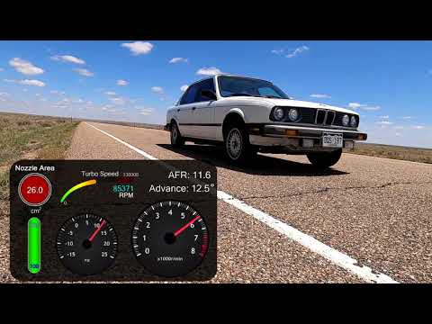
Here's a third gear pull from last night, maybe a little uphill. Note the turbosize and turbospeed parameters in the datalog. Spool might not seem too great for a 60mm/60mm turbo for hitting the throttle at 4000rpm, but there's a big caveat:
When the vanes close at mid-range RPM, there's enough exhaust pressure to force open the wastegate, even with the stiffest spring for my wastegate (~9.5psi up here at 6000', would be ~12.5psi at sea level; it's a JGS 40mm). Going by my ears (wastegate dumps under passenger footwell), the wastegate is basically wide open between 3-6psi above atmospheric, at which point the vanes start to open and the wastegate shuts again until I hit peak boost (around 12.5psi above atmospheric). I can't really hear it when I first hit the throttle, but it might be open then, too. Of course an open gate should give much slower spool.
I don't want to run more than about 15psi (210kPa absolute) any time soon, and JGS doesn't sell a stiffer spring for my wastegate anyway. Conventional electronic boost control with a solenoid wouldn't help too much, since it mostly isn't boost that's opening the gate, it's exhaust manifold pressure. So to fix it I either have to pressurize the top of the wastegate (CO2?), or source a stiffer spring, or make the VGT less aggressive. I don't want to go with the last option, I don't have any apparent surge and the current settings don't hurt my VE very much during spool (not much noticeable difference in AFR in this datalog between fully open and closed vanes).
Table in bottom right shows full spool parameters: ~1.5s to hit target boost at 4000rpm. Minimum turbine nozzle size 7.5cm^2, not too aggressive. Vanes stay fully closed until I'm 65% of the way to my target boost (from atmospheric, I run a baro sensor too; in this case with baro of 80kPa and boost target of 165kPa, the vanes stay fully closed until ~135kPa).
Same log, but highlighting the time period when the wastegate was opening prematurely. You can see the slope decreases for both MAP and turbo speed in a similar way to poorly-tuned electronic boost control:
And finally, same datalog but highlighting the full boost region. With my 2.93 diff, this window corresponds to 75-102mph in 3.5 seconds (gearing checked against GPS speed), not too bad for 167kPa?
Leave a comment:
-
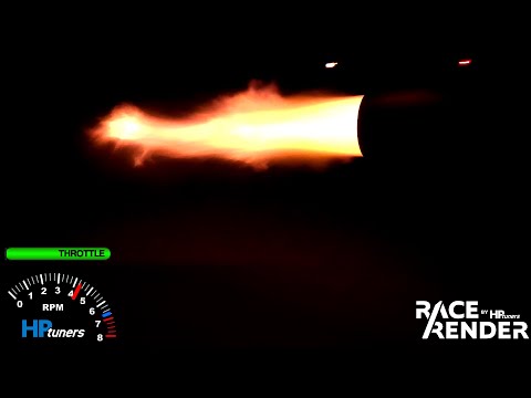
And here's a quick second gear pull from last night, around 9psi - too much wind noise, was trying to get some sound reflecting under an overpass:
Leave a comment:
-
Onwards to the details of my build in this regard; here's the basic structure of how the CAN communication flows between Megasquirt, my microcontroller, and the turbo:
Megasquirt <--> Microcontroller --> turbo
Megasquirt broadcasts data, which is read by the microcontroller. Microcontroller processes the data to determine the VGT position, and sends the command to the turbo. In short - if Megasquirt says we need more boost, the microcontroller determines how badly we need more boost, and closes the vanes accordingly. Once we don't need anymore boost, the vanes open fully to allow the engine to breath as much as possible.
In addition, Megasquirt requests sensor data from the microcontroller, and microcontroller responds accordingly the request, allowing the Megasquirt to log additional data channels.
One of the things that bothered me with previous iterations of the car was the messiness required to display info while I drive - it's tough to really cleanly install gauges, and if you ever want to add additional gauges, it's tough to not make a mess of the splices required. Since I built up the ability to get dozens of channels of data with just a couple wires using CAN, I figured I'd build a solution that takes advantage of it: a multi-function display that can display any info I'm interested it. Expandability is the key feature here: add some code, and you have another gauge. No worrying about how to mount it, where to splice, how to make the wiring clean.
So, as I considered all of these features, I ended up with the following setup:- Standard MS sensors (IAT, TPS, CLT, Crank position, Wideband) wired as usual for MS setups, to the DB37
- Standard MS outputs similarly (fuel pump relay, wasted spark outputs, injector outputs, PWM idle control)
- High-voltage flyback tach circuit added to the regular MS tach output, since the stock tach was triggered by the coil from the factory
- CAN wired as normal for MS
- Fan control using a relay trigger circuit (using the stock high-speed fan relay/wiring)
- Intercooler pump control using a relay trigger circuit (using the stock low-speed fan relay/wiring)
- Fuel pressure sent to the microcontroller (Teensy 4.0) using an analog input
- Oil pressure sent the same way
- Circuit built using a VR encoder IC (MAX9924) to read turbo speed, since HE351VE includes a speed sensor
- Fuel and oil pressure, turbo speed, and turbo vane position (technically, nozzle area in cm^2) sent to Megasquirt for datalogging
- Stock econometer functionality: microcontroller reads injector pulse width from CAN, converts to duty cycle based on engine speed, scales to account for the bigger injectors I'm running, sends it as a PWM output with PWM frequency matched to engine speed, and scaled to a 12V signal with a transistor circuit
- Turbo VGT actuator power controlled by an output on the microcontroller, with corresponding booster circuit on the microcontroller output to power the relay
- Stock OBC (multi-function clock in my case) replaced with a 2.8" touchscreen display with a custom housing and bezel to hold all of the microcontroller circuitry
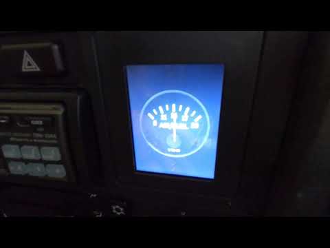
I'll have to get a better video of it at some point - the turbo gauge is pretty fun, shows turbo speed and turbo size as well as boost pressure. Logging that data is really helpful for the VGT tuning.Leave a comment:
-
I mentioned before that my project scope creeped a whole lot for this iteration - originally I wanted the car running with the new turbo by New Year's Day, doing the bare minimum to get there (exhaust manifold, intake plumbing, downpipe, and maybe the rest of the exhaust, reusing everything else as it existed before). I didn't quite make it, and the urgency I felt decreased, so I decided to do it "right" from the get-go, and build things the way I ultimately wanted them to be (at least everything related to getting the car running with the features I wanted to add).
The VGT turbo was a big driver of the feature-creep here. Originally, I planned to use an Arduino to simply read the PWM boost solenoid signal as output by the Megasquirt, convert that to vane position, and send the position with a CAN transceiver - nothing too complicated. Then I started digging into the Megasquirt features a bit more, and realized it could broadcast parameters over CAN, and since I'd be using CAN no matter what, I could read the boost duty over CAN instead of directly from the Megasquirt's boost solenoid output. And if I could read boost duty over CAN, it would be mostly copy-paste to read any other parameter the MS broadcasts.
Here's some of the initial simple VGT bench testing, with the turbo responding to changes in boost vs boost demand as I simulate boost with a syringe hooked up to the MAP sensor:

Then I realized Megasquirt can take CAN data as additional sensor inputs - and since I am quite limited on analog sensors by Megasquirt 2, this could be a huge help for logging things like fuel pressure, oil pressure, turbo speed, etc. Unfortunately, implementing this wasn't super well-documented. Megasquirt CAN data broadcasting is pretty simple - there are a few parameters sent in a given message ID, so check the ID to see which parameters are in the message, then extract them. But to send data back to Megasquirt, a request/response protocol is used. Megasquirt requests data with a pretty highly-encoded data structure: the message ID contains information about which data is being requested, who is requesting it, who it's being requested from, how much is being requested... the request message data buffer contains other info as well, all of which has to be interpreted to understand what exactly Megasquirt is asking for, and how it wants the response to be structured. Once you interpret this, you have to build a response in exactly the way Megasquirt requests - and if you succeed, Megasquirt will take the data you sent and store it in the 8 virtual GPIO channels it has, at which point you can set up functions in TunerStudio to interpret those inputs.
I'm definitely not a developer, but I figured since I'd have to do the work anyway, I'd build an Arduino library that anyone could use to do the same thing. It contains ALL of the broadcast parameters than can be sent by a MS2 or MS3, and methods for receiving, interpreting, and responding to Megasquirt requests for CAN data.Last edited by mikey.antonakakis; 05-13-2020, 11:58 AM.Leave a comment:
Leave a comment: