-
Man, I would LOVE to be able to afford to take one of the sets of Bottle caps I have and make 3 piece wheels out of them. It would really add to the dumpster fireness of my dumpster fireLeave a comment:
-
From time to time I've been thinking about the 3-piece TRX conversion and considering different ways to set them up. My original idea was to do a budget project and just mate TRX centers with RC 090 barrels. The wheel offset would however have been less than optimal. Also the shape of the TRX center poses some issues. There's quite little material to machine at the outer edge. I considered different options. For a while I was happy with using just the rear barrel from RC090, buying outer lips and bolting both to the backside of the center. However I would need to countersink the bolt heads and there's not quite enough space for that in the center. Also I decided I want a more traditional 3-piece look with the center between the lip and the barrel.
Render of lip and barrel both behind the center:

Classical look:

The center will need some fill in welding at the backside and the front flange surface will be slightly undersize so there will likely be a small gap behind the inner edge of the front lip. It should not matter for the structural integrity but there will be a tiny cavity collecting dust. When I sliced up the first TRX wheel I removed too much material so I need to get one more. That was not in vain though. It needed to be done to get a better sense of what's possible and what's not. I cut up a second wheel and ordered an aluminium ring to act as a filler piece. A welder I know welded the ring in place from two directions making it a solid piece without cavities.

I cut up the RC barrel with a grinder.

From slicing up the first TRX wheel in lathe I also learned that it's difficult to attach the wheel to lathe rigidly enough to produce a true wheel and to avoid vibrations during machining. So I made as sturdy a jig as possible. I had a hub plasma cut from 25mm steel plate and drilled and tapped holes for lug bolts in it. Then I cut the center hole to size in the lathe to fit a 60mm axle.
I welded the hub to the axle and then turned the faces in the lathe. I also made a centering shoulder to fit the center bore of the wheel on both sides of the hub. This way I can bolt the wheel onto either side of the jig to easily machine both the front and the back face.


Then it was just a matter of fixing the wheel to the lathe and letting shavings fly. Our lathe couldn't possibly fit any bigger object.


It doesn't show in the picture but I machined a flange surface with a centering shoulder also on the back face. Currently the edge is quite thick. I'll still remove some material both from the front and the back face but I'll decide how much once I have the axles in the car and can do some test fitting. I also need to decide how I want to do the 5-lug conversion but all of that will be in far future. The first wheels will anyway be the 4x100 BBS RS's that I built earlier. When doing the 5-lug swap I want to either trade or rebuild these to 5x120 to be able to run either RS's or TRX's as the mood swings.

Fun fact: One of my TRX wheels is of brand Alcoa while the resr are BBS. They look slightly different. Alcoa has sharper edges so it will need some sanding to get the same look as in the BBS ones. Hopefully the shape is same enough regarding the machining.Last edited by Skarpa; 04-03-2018, 12:04 AM.Leave a comment:
-
I dislocated my knee cap again :roll: Sometimes I question the sanity of doing contact sports. The knee is not too bad, though. I can already move without crutches but it doesn't like it when I stand too long so at the garage I had to focus on stuff I can do while sitting down.

I welded a reinforcement plate to the brake pedal where the fork of the booster meets the pedal.

Then I smoothened up all the parts of the pedal assembly and plugged all the threads for powder coating. I also took apart the headlights to have the frames powder coated. Lately I've been making a list and preparing all the rest of the parts that I want either zinc plated or powder coated.

Leave a comment:
-
The engine bay battery tray is almost ready (or rather the place where the battery tray used to be). Earlier I came to conclusion that I don't want to preserve any remaining traces of the unnecessary contour so instead I made a template of straight panel to replace it.


I made the corner of the wheel well to match the one on the driver's side.

I glued the overlapping seams on top because I didn't want to burn seam sealer in difficult places by welding.


Other seams I of course welded.

I drew the position of the main power cable and engine ecu wire loom openings. I'll use the brake master cylinder grommet for the main power cable. It's correct sized and has a suitable angle. However, I'm not entirely happy with the position of the openings. The positive terminal and the ecu wire loom are pretty cramped. I think I'll drill another hole for a nutsert and move the positive terminal sideways to give space for the ecu wire loom. Then I wouldn't need to place it quite so low.
Another issue I needed to tackle was the bracket for the glove box hinge. Normally it bolts to the bottom of the battery tray which I just got rid of. I decided to make a bracket as a lightweight version of the original shape.


And that's how far I got. Should be finished the next time.Leave a comment:
-
Got a small job done. When I relocated the ABS unit the bracket required some modifying. It needed to be mirror image of itself to be precise. Back then I just beat it to submission to be able to mock the ABS unit up. I knew that some day I'd need to do it properly and that day was today. I drew the shape of the bent bracket and then flattened it in a hydraulic press to take a pattern.

I cut a new piece of sheet metal in shape and left some extra near the bends to have something for the bender to grab to.


After bending I cut off the extra bits and made the half circle allowance bend in the middle with the help hof some plywood, hydraulic pipe and a press.


Ready to be yellow zinc plated.Last edited by Skarpa; 03-07-2018, 08:28 AM.Leave a comment:
-
When finished, Armo will have a throttle response like this:
PS. I now have a full control over the gauge needles. In this clip I'm driving the needle directly, not through the rev count signal. The econogauge control is the same.Last edited by Skarpa; 02-28-2018, 01:42 AM.Leave a comment:
-
Ooh, I started a poll :D
I haven't had time to spend at the garage but I've been tinkering with several projects related to Armo. One of them is the oil temperature gauge. A while ago I decided to replace the momentary fuel consumption gauge (the most useless gauge ever) with an oil temperature gauge. I studied the gauge and found out that it's not possible to control it with a simple voltage signal necause there are two coils for controlling the needle movement and they need to be powered in correct relation for desired needle movement. I bought an Arduino Uno to control the gauge.
While waiting for that I drew the gauge face in cad and had it printed on matte vinyl sticker which was glued on a piece of laser cut plastic sheet.

I had stickers made with two different shades of glue layer so I can test which one produces the best back light colour and brightness.

Darker, grayish brown glue layer gave a better result. The original gauge face has additional shading on the right side where the back light bulb is closest. It seemed to be necessary so I glued an additional piece of sticker behind the gauge face. That gave pretty equal illumination.


Next I needed to find out what kind of voltages the instrument cluster uses to control the needle movements. I coded a simple square wave generator on Arduino and used that to connect the speedo sensor wires via a photo isolator relay. However, the relay was not ablee to produce signal for road speeds over 60 km/h. I'll need to get a more suitable component for testing.
Once I have the control figured out I'll share the Arduino program as well as the files for the gauge face.Last edited by Skarpa; 02-25-2018, 07:26 AM.Leave a comment:
-
mtech1 is definitely my favorite look, second is prefacelift bbs kits. Love me an early modelLeave a comment:
-
It's been a while since last update but don't worry, the project continues with the same glacier-like speed as always. Actually I've recently had quite a lot going on but not much to show for it yet. But here's something.
A workmate welded a tailor fitted banjo connector to a hose barb I turned earlier.
I pressed the E36 M3 rubber bushings to the painted lollipops. I'll mount the lollipops on the control arms once the control arms are going under the car so they'll settle in position while still lubricated.

I cleaned and assembled the rear shocks. Not much to say about them. They are yellow and of questionable quality. Certainly not Bilstein or Koni but they worked ok the last time they were under the car. I'll switch to better ones when these are done.

All mocking up related to the engine is done so I dropped it from the body and started working on the battery shelf. I drilled off the spot welds and started thinking about what I want in its place.

Earlier I planned to just trim the battery shelf and use the M3 plastic cover but I've decided that I mislike that look. The plastic cover has many useless (for me) contours and even if I trim the lip in the bottom I'm still left with a funny sliver of battery shelf showing.

I'll ditch the M3 cover and lose the whole battery shelf indentation. Instead I'll make straight panel in the shape of the surrounding firewall and do the wheel well in the same shape as on the driver's side. On the cabin side I'll need to make separate brackets for the glove box hinge. The main power cable and the ecu wire loom will have pass-throughs with rubber grommets in the new panel.

A few days ago I was looking at pictures of a zinnoberrot M-tech 1 and thinking to myself that that's pretty close to how I picture Armo when finished. The major difference on the outside was that this car had the older style M-tech side skirts without the upturned ends. When looking at the pictures I realized that the ends of the newer side skirts have always seemed a little off in my eyes. After small pondering I sold the skirts I had and bought the older style skirts off ebay. With the straight skirts the side profile of the car will be more streamlined. The bottom line of the valances and the skirts and the side trim line are more continuous without distractions. A couple of pics robbed from internet to demonstrate the difference:
Older style:
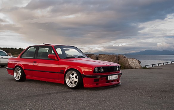
(This is not the "future Armo" pic. I'll keep all the chrome in the car)
Versus the new one:
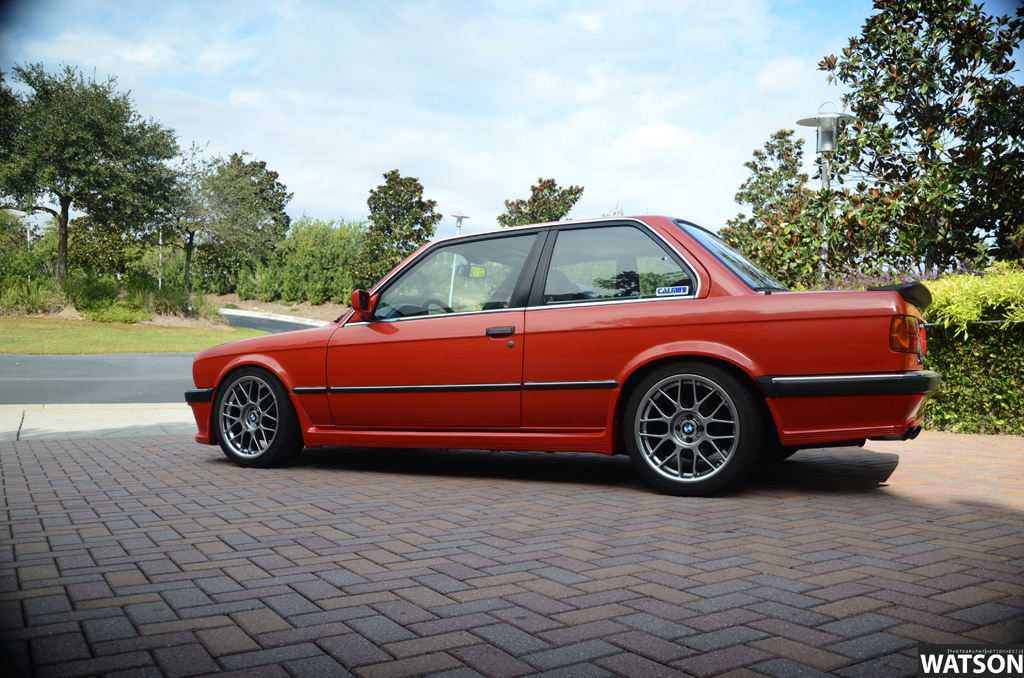 Last edited by Skarpa; 02-13-2018, 03:30 AM.
Leave a comment:


Leave a comment: