
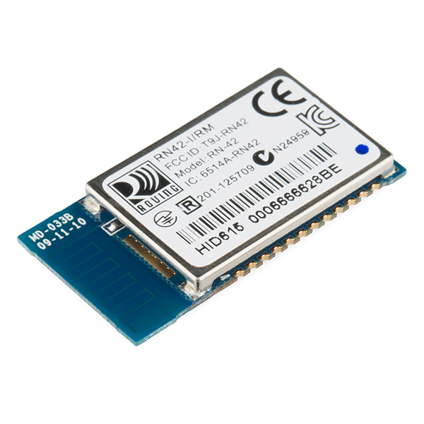
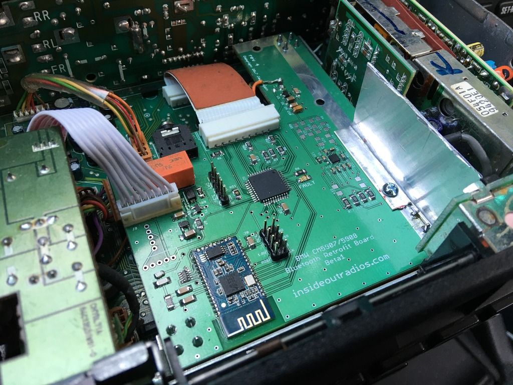
That module should have provisions for an antenna pin. Looks like if you desolder the 0402 jumper leading to the antenna, and move it over to the left position, that lets you wire an antenna to pin 43.
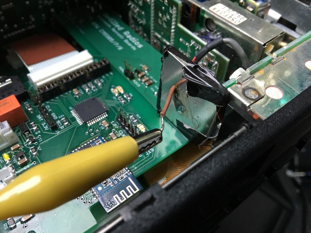
I'm guessing what you did, is you messed up the impedance matching of the antenna, so you ended up weakening the RF signals. It's no longer a nice fraction of a wavelength.
Normally those little modules (FCC certified ones) have a shield covering everything except the antenna, wonder if that might help?


Comment