Announcement

Collapse
No announcement yet.

E30 M42 to Motronic 1.7.3 Conversion Project

Collapse
X
 
  • Filter
  • Time
  • Show
Clear All
new posts

    #46
    Originally posted by Rasp View Post
    Do you look XDF for M1.7.3? What tables are you going to look for? :)

    Tables will not help you in understanding the code, they will only harm you. Schematic and description of variables and bits in memory will help much more. Tables and values is a result of disassemble, not reference point.
    actually, they do help - because you can see what they are doing in software, not just what they are. For example, you know that one constant affects another map, or a switch branches between two parameters, etc.

    I don't consider it a complete disassembly unless the parameters are all mapped - an XDF isn't going to do that for you (but it can help). It's not about looking for definitions or tables at all. With a fully mapped out IDA project you can do interesting stuff with different software versions.
    Build thread

    Bimmerlabs

    Comment


      #47
      Originally posted by Shock(/\)ave View Post
      I've been following your efforts with extreme interest for the past few months. If this project is successful, we could finally have an upgrade path for the S14B23 and S38B35 motors from Motronic 1.0 among others.

      Have you any idea what a completed board with components might cost? I have three cars which would benefit greatly from this project.
      It isn't possible to build a PCB and populate it, or at least not with new parts. Many of the components are custom and not available for purchase, so even if I made a 28/35/55 pin version PCB I wouldn't be able to construct it without eBaying a bunch of stock ones and harvesting parts. Given the hourly rate that I bill for this type of work, it would not be remotely worth it because of the time involved.

      I think that the best option would be to get the 88 pin connector from a wrecked M44/M5x/S5x car (or any of the ones that used the 88 pin conn) and adapt that onto your factory harness. It is not terribly hard to pop the wire terminals out of these connectors, so you could do that and insert them into an 88 pin connector for an almost-factory setup, and then plug directly into a stock M1.7.3.

      Originally posted by nando View Post
      actually, they do help - because you can see what they are doing in software, not just what they are. For example, you know that one constant affects another map, or a switch branches between two parameters, etc.

      I don't consider it a complete disassembly unless the parameters are all mapped - an XDF isn't going to do that for you (but it can help). It's not about looking for definitions or tables at all. With a fully mapped out IDA project you can do interesting stuff with different software versions.
      I am very excited to try to build up a block diagram for all of the fuel and ignition calculations. It sounds like all of the corrections are basically done in individual steps using constants and LUT's to modify base values. There's also the map switching that gets done, and at least in M1.7 I have no idea why there are multiple slightly-different copies of fuel & ignition maps, and why the ECU will mostly pull from one set, but occasionally jumps to others. There is no fuel quality sensor, no knock sensors, etc...so I am super curious about the reasons for it.

      I think that Rasp's point is that, in terms of priorities, figuring out what all of the IO pins and RAM bit switches do is sort of the first priority since so much functionality comes from there. Certainly, getting a handle on all of the different maps, what they do and when they are used is also very important. Once we have a full understanding of the IO's and switches, I think that some of the map stuff will be made more clear. But, since multiple people are in here, interested and motivated, it seems like a fine idea to have different people working on different parts of this.

      I can create a directory in the Dropbox and give you write access if you want to start working on your own IDA project to identify maps and their specific functions.

      Transaction Feedback: LINK

      Comment


        #48
        Also, I have been working on actually testing connections and verifying how certain signals function. Just basics for now, but I want to get my function generator on the O2 and knock inputs, at the very least, to see how the custom chips they connect to handle those inputs.

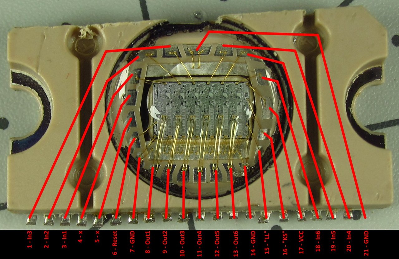
        S400/450 was pretty easy. The little black cover came off with minimal grinding and prying, allowing me to directly see which pin goes where. I now know 100% which inputs map to which outputs. The LL and KS pins are a little bit of a mystery still, but I am assuming that they are enable/disable lines of some sort. I can think up ways to test that.


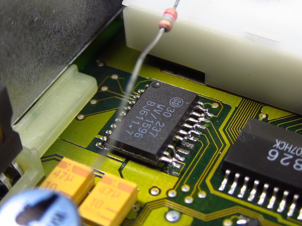
        For S500, I was able to test things directly. In order to ensure that I would not damage the IO pins on S702 by forcing the S500 inputs into different states, I used the soldering iron to lift the input pins and the enable pin (#11) and pull them to ground with a resistor (when left "floating" all of these pins are internally pulled up to 5V). When the enable pin is in a low state, S500's outputs are disabled, and when it is high the outputs are enabled. The 6 inputs are inverted, meaning that a high input corresponds to an inactive output / low input is an active output.


        More to come as I put as much detail into the schematic as possible!

        Transaction Feedback: LINK

        Comment


          #49
          Originally posted by bmwman91 View Post
          I am very excited to try to build up a block diagram for all of the fuel and ignition calculations. It sounds like all of the corrections are basically done in individual steps using constants and LUT's to modify base values. There's also the map switching that gets done, and at least in M1.7 I have no idea why there are multiple slightly-different copies of fuel & ignition maps, and why the ECU will mostly pull from one set, but occasionally jumps to others. There is no fuel quality sensor, no knock sensors, etc...so I am super curious about the reasons for it.

          I think that Rasp's point is that, in terms of priorities, figuring out what all of the IO pins and RAM bit switches do is sort of the first priority since so much functionality comes from there. Certainly, getting a handle on all of the different maps, what they do and when they are used is also very important. Once we have a full understanding of the IO's and switches, I think that some of the map stuff will be made more clear. But, since multiple people are in here, interested and motivated, it seems like a fine idea to have different people working on different parts of this.

          I can create a directory in the Dropbox and give you write access if you want to start working on your own IDA project to identify maps and their specific functions.
          Sure, for you guys, that makes sense - but that's why it's good to collaborate! I'm probably not ever going to run Motronic 1.7.3 on a car - and I won't be much help with those things anyway.

          I do on the other hand have tools that I've built to make completing an IDA project much faster (with map names populated etc). It's just a matter of getting it to reference the data properly - which for me is also a learning exercise, and making sure I don't forget how to use it, and exposing myself to other types of ASM code. Probably 90% of my experience is with PPC, 9% with TriCore, and 1% everything else. I've always wanted to look at early Motronic, so a project that's already started seems like a good place to begin.

          If you want to share a dropbox folder, that's perfect. That's how I usually work on IDA projects with other people anyway. This one is pretty small - I might be able to just map everything manually. I'm not kidding when I said the whole ROM is smaller than the boot code on a modern DME. But that's a good thing for you guys. :)
          Build thread

          Bimmerlabs

          Comment


            #50
            The more the merrier. I can totally understand doing something simply for the joy of learning. The realistic side of me figures there is a 50% chance that I will ever get my car running on this, but it is worth a try and this is all super interesting, even if it is completely obsolete technology.

            Based on the other experience you describe having with ASM, this should be pretty straightforward. I definitely want to know the finer details of all of the maps since this all started with me working on a custom tune for my 2.1L M42, and I'd like to finish there too lol. Due to various quirks, and assumptions which may still be proven false, I feel like I need to fully understand the maps and their actual functions in the code to really nail the tune down.

            PM me an email address and I'll add you to the Dropbox.

            Transaction Feedback: LINK

            Comment


              #51
              Originally posted by nando View Post
              I'm probably not ever going to run Motronic 1.7.3 on a car - and I won't be much help with those things anyway.
              In this case, you are unlikely to help something. No offense. The size of the code here does not matter.

              Comment


                #52
                OK, the first draft of the schematic and layout are up on the Dropbox under the ECAD directory. If you find errors let me know so I can make corrections.

                The big delay has been in figuring out the knock sensor subsystem. There is a lot going on, and luckily I was able to figure out what S253/4/5 are which helps a lot. The main chip, S252, is still somewhat of a mystery, but I think I can figure out more with my signal generator and oscilloscope. Mostly, it appears to put out a ~11.25kHz square wave which is modulated with the knock sensor signals to provide some excitation to the sensors and maybe to also shift the signals' frequency spectrum for easier noise rejection / bandpass filtering during demodulation. Hopefully I can figure it out. The TTL crank position pulse signal is also used in S252 and it seems to be mixed in with the modulated knock signal, the 80C535 can enable/disable individual sensor inputs and the modulation, etc. A lot going on.....

                Transaction Feedback: LINK

                Comment


                  #53
                  Originally posted by Rasp View Post
                  In this case, you are unlikely to help something. No offense. The size of the code here does not matter.
                  No offense taken - but I've disassembled multiple DMEs for cars I don't own and will never run, and all of them are useful. :)

                  Anyway, talk is one thing, action another. If I have results and you think they are helpful, great! :)
                  Build thread

                  Bimmerlabs

                  Comment


                    #54
                    Originally posted by nando View Post
                    No offense taken - but I've disassembled multiple DMEs for cars I don't own and will never run, and all of them are useful. :)

                    Anyway, talk is one thing, action another. If I have results and you think they are helpful, great! :)
                    Which all DME's have you done? I am certainly interested in some of the lessons you have learned along the way. I think I am going to turn my attention to the firmware fairly soon since I have at least identified the various IO's, and while I want to more fully characterize S550, S600 and S252, understanding the code as it relates to those may be the next most helpful thing.


                    I did do some experimenting with my function generator and the O2 sensor input as well as the crank position input. I need to test more, but it seems like the stock crank sensor input conditioning is not very good in that it does not seem to filter out offsets. Inputting a sine signal and then giving it a DC offset causes the TTL output pulses to change in timing since it seems to be a somewhat basic zero-crossing detector, which also does not quite align with crossings at zero, but rather at ~0.7V. I have seen signal captures from the actual sensor, and due to manufacturing tolerances and the motion of the damper, the signal coming out of the crank sensor has its own varying DC offset with crank speed and position. This would have an effect on the accuracy of the ignition timing. So I wonder if adapting a MAX9926 in there to provide the TTL crank position signal would lead to improvements in crank position measurement accuracy. However, since it is a very good adaptive zero crossing detector, I am guessing that some amount of software adjustment will be needed since it is probably programmed to deal with the fact that the stock TTL crank position pulses are made at some point after the zero-crossing. This will probably read as a little confusing, so I will try to get images from my oscilloscope to show what I mean.

                    Transaction Feedback: LINK

                    Comment


                      #55
                      Originally posted by nando View Post
                      Anyway, talk is one thing, action another. If I have results and you think they are helpful, great! :)
                      Yes, thats I mean :)

                      Almost all the information that could be obtained without debugging on a real ECU is already there.

                      I'm update RAM definition and XDF on Dropbox.

                      Comment


                        #56
                        Originally posted by bmwman91 View Post
                        Which all DME's have you done? I am certainly interested in some of the lessons you have learned along the way. I think I am going to turn my attention to the firmware fairly soon since I have at least identified the various IO's, and while I want to more fully characterize S550, S600 and S252, understanding the code as it relates to those may be the next most helpful thing.
                        We have MS45.0, MS45.1, MSS70, MSV70, MSV80, MSD80, MSS60, MSS65, MSS54, ME9.. and sometimes multiple versions of each (once you have one built, it's pretty easy to build second one). it seems like a lot, but actually some are so similar you can start one from the other (MSS70/MSV70, MSV80/MSD80, MSS60/MSS65). I built a new version of MSS60 the other day in about 20 minutes - most of it just some minor cleanup. :)

                        Now, actually understanding and using the project once it's created is something else! But I think that's where you come in, because you should be able to see what parts of hardware are being activated by software, and which maps control them.

                        I actually did get some parameters to reference - but I need to look more closely at how the data-pointer works, as I think it changes depending on the code section you're in and which map it selects (AT vs MT). I think I would just have to assume MT and go from there (or build a separate project for AT/MT).

                        So for example the crankshaft sensor segment references are there, and the cylinder count and segment length aren't. But I think that's because the base offset for those two is based on which segment length it chooses (AT or MT).
                        Build thread

                        Bimmerlabs

                        Comment


                          #57
                          Originally posted by nando View Post
                          So for example the crankshaft sensor segment references are there, and the cylinder count and segment length aren't. But I think that's because the base offset for those two is based on which segment length it chooses (AT or MT).
                          Cylinder count and segment length is defined in parameters.

                          M1.7.3 has several tables selector AT/MT, KAT/NO-KAT,92/95,LEADED/UNLEADED and other things.

                          Comment


                            #58
                            Right, I know that - what I'm saying is in the code, it references those parameters differently depending on what table it selects (AT or MT, etc).

                            The parameters aren't just there by magic - the code has to read them somehow. I only figured out a small portion of the references; they are all there - I'm just not certain what they are offset by yet, since I don't know the actual contents of DPTR.
                            Build thread

                            Bimmerlabs

                            Comment


                              #59
                              I got high magnification images of a few additional chips' dies today. I have been finding these to be somewhat helpful with figuring out some chips' connections. A few features are starting to be recognizable (resistors, capacitors, some transistors) so I think I may be able to figure out some functionality directly. Anyway, pics are in here if you are interested (the ones I added are all full size this time, some are fairly large).


                              I also put copies of the schematic and PCB on my own site, in addition to Dropbox so that anyone can access them without a Dropbox account.


                              Transaction Feedback: LINK

                              Comment


                                #60
                                Good work bmwman91, thanks a lot!

                                Looks like 27C512 can be directly replaced with 28F512 if change chip connector (sorry, I'm dont know how its named in english, we call it "crib" if translate :) ).
                                Thats completely solves the problem with online (not bench with programmator) flashing.
                                Another plus in the piggy bank for M1.7.3.

                                Comment

                                Working...
                                X