
Originally posted by captain awesome
View Post
-
The exhaust is some no name exhaust. I think the cat is blown open which is why it is a little loud. It had been stored but I picked it up yesterday and have that list above to fix on it still. Planning to do the reverse light, steering wheel and maybe spoiler if I have time this weekend. I put the fuse back in for the hvac fan and it stayed off when the car was off so I think there is some electrical gremlin somewhere.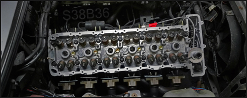 318iS Track Rat :nice: www.drive4corners.com
'86 325iX 3.1 Stroker Turbo '86 S38B36 325
No one makes this car anymore. The government won't allow them, normal people won't buy them. So it's up to us: the freaks, the weirdos, the informed. To buy them, to appreciate them, and most importantly, to drive them. -
So the car developed a slight misfire and after driving it I was pretty sure it was the fuel pump which I replaced last year with a carquest special. So I ordered a Bosch 040 after reading that it is a drop-in replacement for the in tank pump and that it can support crazy amounts of horsepower. However the company I bought it from says it was out of stock and will not ship for 3 more weeks...
So the cluster had been at a friends shop for a while and after I picked it up, it was not in the same condition as I dropped it off. The needles were replaced with some orange (possibly 3D printed) ones and the gas gauges wasn't reading right as well as some of the screws, so I took it apart to repair. Here was when I got it back.
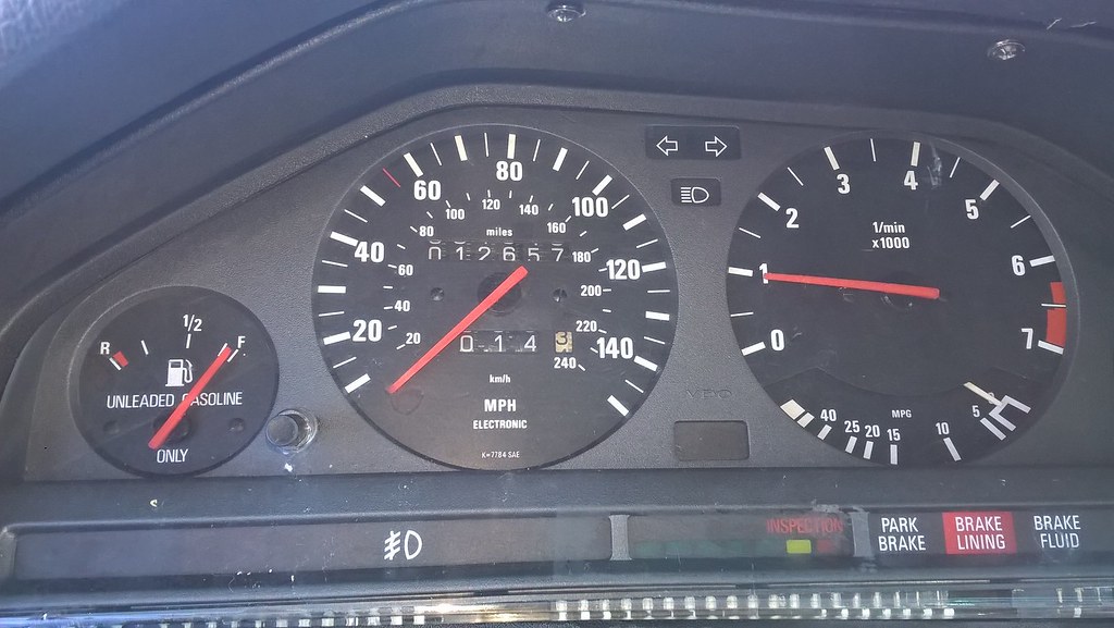
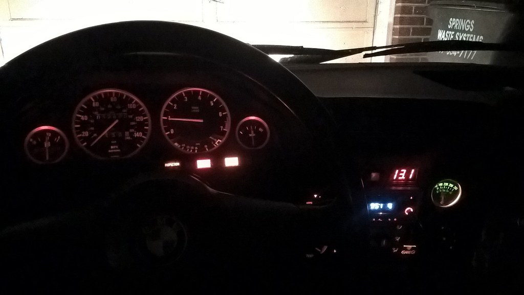
And I had some chrome trim rings laying around so I put them in before they get broken. I am on the fence about it. I also took the center console apart a fixed the temp gauge bulb that was burnt out. Here is how it looks at night now. I may add more light since it is still dark inside.
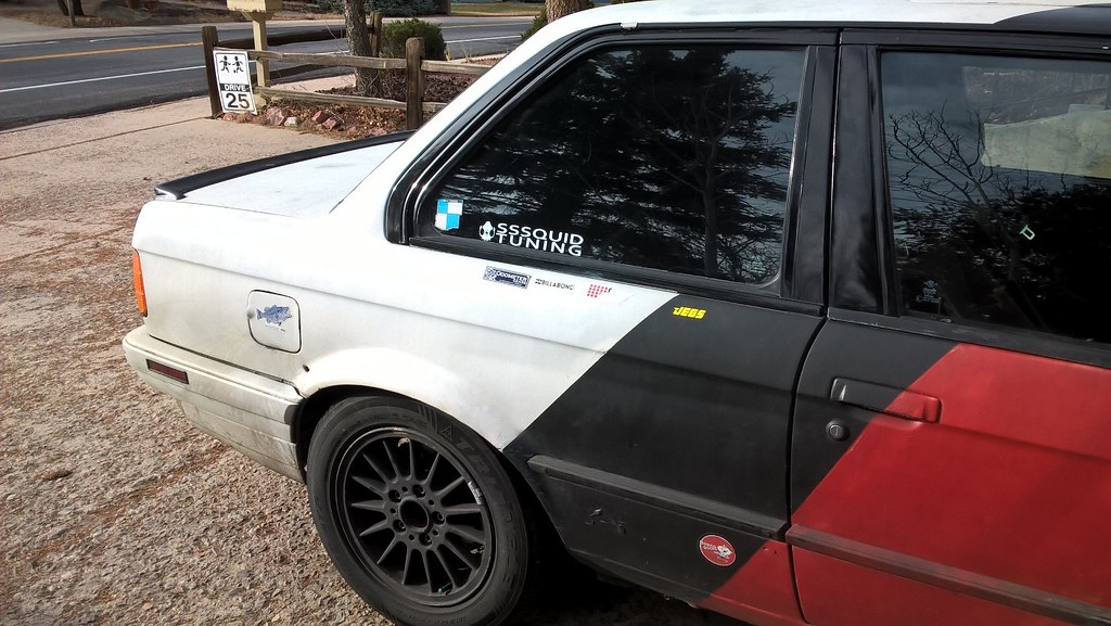
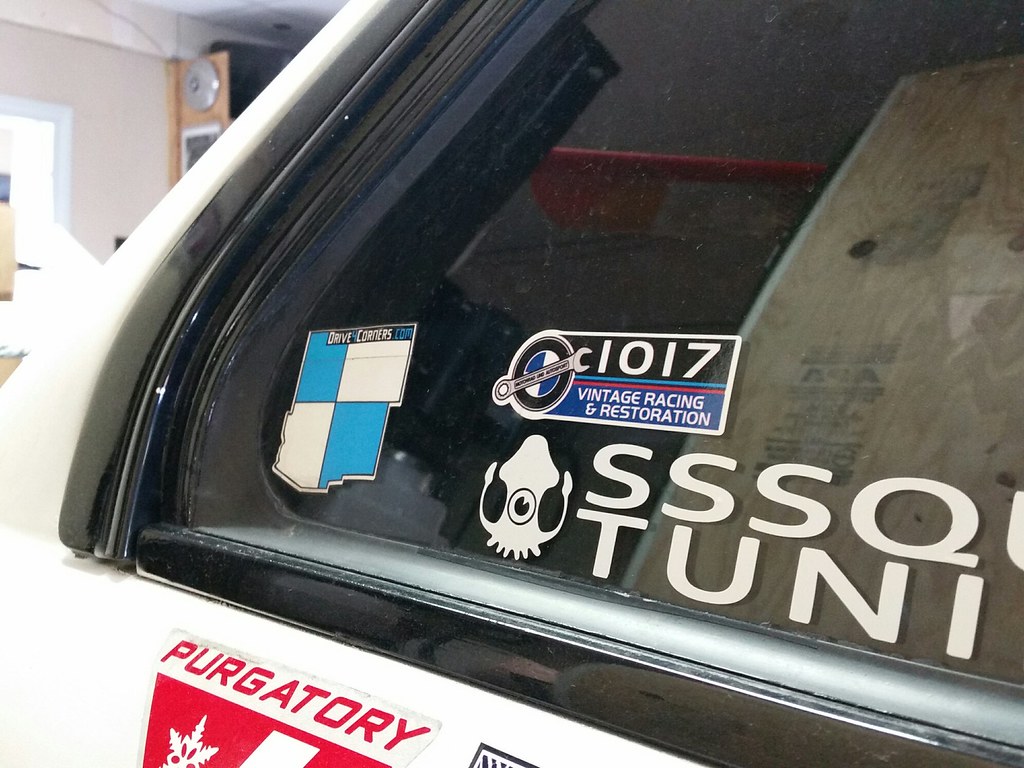
With a new chip in the car, I had to represent my tuner so here is the latest decal.
Then I found a deal on a 360mm raid steering wheel. The wheel is small and without power steering can be hard to turn when going slow. I am unsure if it will be good on track because of the amount of effort required. It also block the top of the gauges where you would see the 70 mph mark and the 4-5-6k rpm area. But it looks cool and feel pretty good so I may keep it for a while or revert back to power steering.
I tried to install the new reverse light switch but the reverse lights still dont work so I need to check the wiring eventually. Also the hvac fan did not stay on, I have heard it could be a sticky relays that causes this so I may replace it soon, but it has been working correctly lately so I am not worried about it.
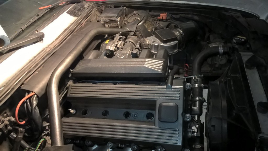
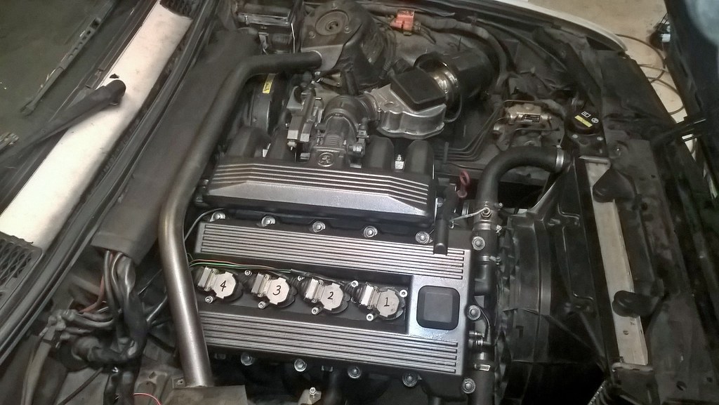
Recently, I found a Coil on plug kit for sale so I picked it up and installed it last night.

I don't think I picked up any power but the engine does not misfire anymore and seems to run smoother at low rpms. I still have the fuel pump coming and will have to see if the fuel pump was causing problems or if it was just the wires and oem stuff causing problems.
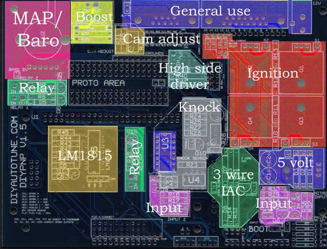
The last thing I have been looking at is running the m42 on megasquirt. I picked up a spare diypnp 55 pin ecu and may make an adapter to run the 55 pin ecu. I need to see what matches up with what but there are only a couple of items that may need some time spent to figure out. I was curious about how to run the ignition and found base setting and this guide on the diy page.
Direct Coil Control
Rule of thumb: If your coil has only two terminals, and there’s no ignition module outside the ECU, use this. Also applies to 4 cylinder coil packs with 3 terminals and 6 cylinder coil packs with 4 terminals when not used with an external ignition module.
Common in Bosch and Seimens ECUs, almost unheard of in ECUs of Japanese origin. There is no external ignition module, and the ECU controls the current running through the coil directly with a power transistor. You can order BIP373 power transistors to install in the DIYPNP for these types of ignitions. On cars which originally used an external ignition module, this can open up other ignition options directly controlled by the ECU. For example, if you want to convert your ’90-’97 Miata to use one MSD coil for each plug, you can use these outputs to fire the coils without an external ignitor.
The BIP373s install in the Q1 through Q4 slots, using a heat sink as included in the DIYPNP BIP373 mod kit. Here’s what components are in each spark circuit.
Spark A: Q1, R13
Spark B: Q2, R12
Spark C: Q3, R11
Spark D: Q4, R10
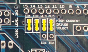
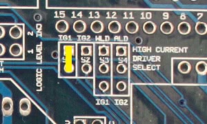
When using the high current ignition drivers, they must be enabled with the jumpers marked High Current Driver Select. These jumpers are marked S1 through S4, for spark outputs 1 through 4 respectively. To enable the first two high current drivers, jumper the lower holes to IG1 and IG2. The second two may be enabled in sequential or wasted spark fashion. Jumpering the middle holes to WLD and ALD will trigger these from WLD and ALD respectively, allowing for sequential coil on plug on a four cylinder or wasted spark on a six or eight. Jumpering the center holes to IG1 and IG2 will allow “wasted spark COP” output on a four cylinder, letting you use two processor outputs to fire four coils in a wasted spark fashion.
Spark Output DIYPNP
The picture above shows it jumpered for four separate spark outputs. You’d set it up this way for 4cyl sequential ignition, or for 8-cyl wasted spark (using two 4-tower wasted spark coil packs). All outupts, S1, S2, S3, and S4 would be used. These are the outputs to the ignition coils.
Changing the second two jumpers drives all four transistors from the IG1 and IG2 signals for wasted spark COP on a 4cyl. (Wasted spark COP means having an individual coil for each cylinder, but firing them in pairs in a wasted spark manner.) You would still use all four outputs with this configuration, S1, S2, S3, and S4.

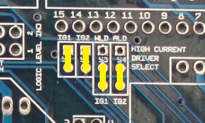
Using only the first two jumpers as in the above image would control a 4cyl wasted spark configuration, such as controlling either one 4 tower coil pack, or two dual tower packs. This setup would use only outputs S1 and S2.
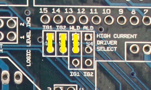
The above configuration would be for either 3cyl sequential or 6cyl wasted spark. Outputs S1, S2, and S3 would be used for this setup.
Using only the first jumper would be the correct configuration for direct control of a single coil used with a distributor. Only output S1 would be used in a single coil setup.
If using spark outputs C or D, you’ll need to install 100 ohm, 5 volt pull up resistors in the R2 and R1 slots respectively.
Spark A: S1
Spark B: S2
Spark C: S3 (requires MS2/Extra 2.1.1 or higher, or wasted spark COP jumpers)
Spark D: S4 (requires MS2/Extra 2.1.1 or higher, or wasted spark COP jumpers)
Spark output must be set to Going High / Inverted.
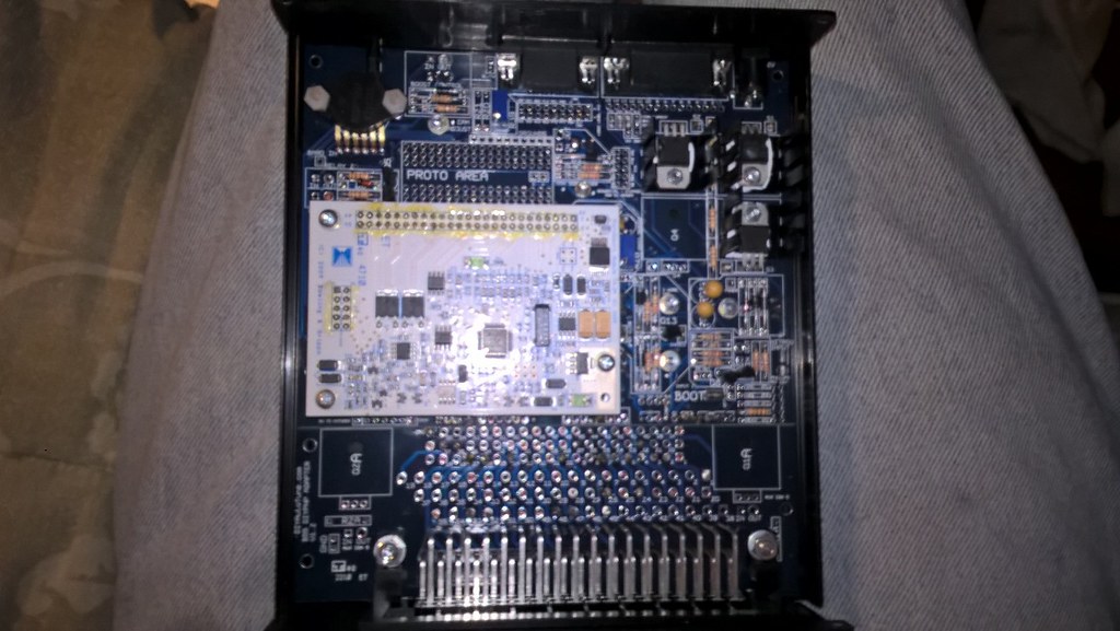
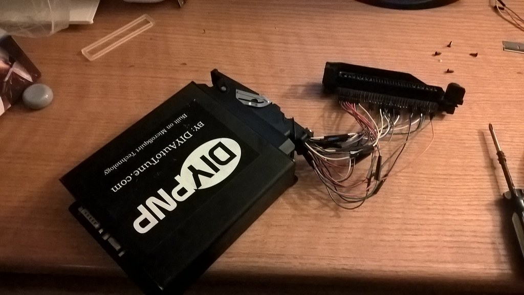
I took the DIY 55 pin cover off and looked at what was there. It looks like it has 3 BIP373 drivers.
Here is the settings varg was running on his m42:

(https://www.r3vlimited.com/board/sho...d.php?t=374858)
Here is my question. Can I run the m42 with wasted spark by using only 2 of the coil drivers (wasted spark)? If so, where do you set this up in the tunerstudio program?
Should I add a fourth BIP circuit so I can run each coil individually (sequential)? Do I need to? Am I looking at this all wrong?
e30 turbo bottom mount for reference http://www.m42club.com/forum/index.php?topic=7731.165
A couple links for future reference


MODEL 318 is/ti 16v
STANDARD 140 HP/6000 - 175 NM/4500
TURBOCHARGED 182 HP/6000 - 254 NM/4500
Boost developed as low as 1200 RPM
Up to 55% increase in torque
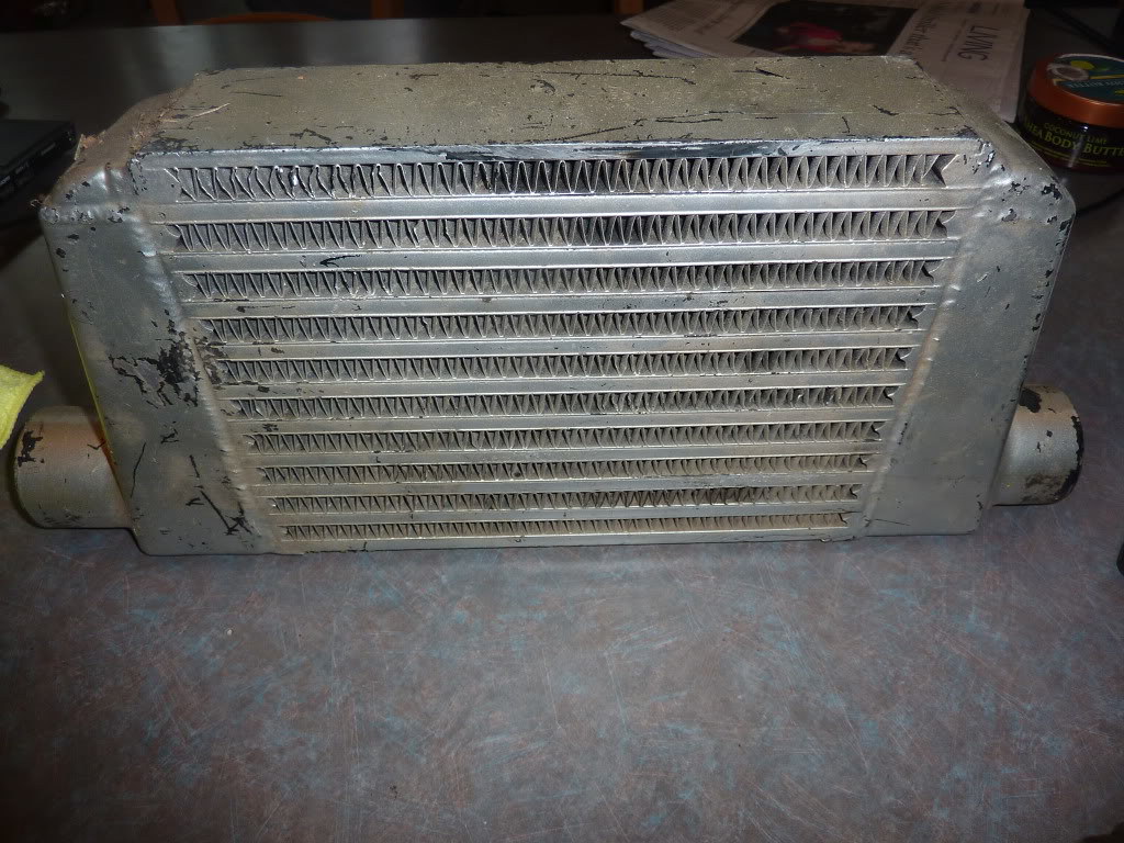
Air to air intercoolers
T25 Garrett Airesearch Turbochargers with integral, adjustable wastegate
Low boost (5.5 psi), no internal engine modifications required
Nodular cast iron exhaust manifolds with 35% nickel for long service life
Aeroquip oil lines, silicone hoses, black powder coated tubing
Complete Intercooler KIT
Engine noise reduced 2-3dBLast edited by downforce22; 02-06-2018, 04:52 PM.318iS Track Rat :nice: www.drive4corners.com
'86 325iX 3.1 Stroker Turbo '86 S38B36 325
No one makes this car anymore. The government won't allow them, normal people won't buy them. So it's up to us: the freaks, the weirdos, the informed. To buy them, to appreciate them, and most importantly, to drive them.Comment
-
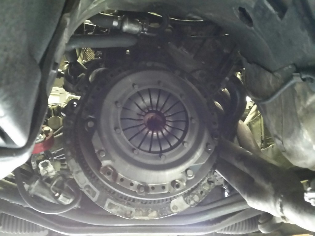
I have been driving this car around a lot lately and thinking about what it needs. Last time on the track after long sessions on the track the clutch would slip a bit so I think it is nearing the end of its life.
With that in mind, I remembered I had a lightweight m20 flywheel and started looking into m20 flywheel conversions. It turns out it is pretty easy and maybe with some luck the flywheel will fit without modification since it has been machined down on the back side for lightening. The flywheel is under 11 pounds. I dug through the garage and found an m20 starter and found a local unused sachs m20 clutch and pressure plate for sale and picked it up. I bought a new pilot bearing and just ordered a TOB and shorter flywheel bolts for the conversion. The only thing I am missing is the clutch alignment tool. So I will be dropping the trans for the swap and see how it compares to the stock dual mass flywheel. While I am in there I may replace the shifter components to freshen it up.
With an upgraded clutch, I decided I might as well replace the pointy cam gears from earlier in this thread. That starts a chain reaction of 'while you are in there' and I ordered new timing components, new chain, and as it turns out, used cam gears which as NLA. The whole front covers will be resealed and hopefully I can get rid of the slight oil leak from the covers. While I am at it, I will reseal the oil pans and check the upper oil pan bolts to make sure they aren't rolling around in the pan. With the pan off I will purchase an oil drain and get that installed.
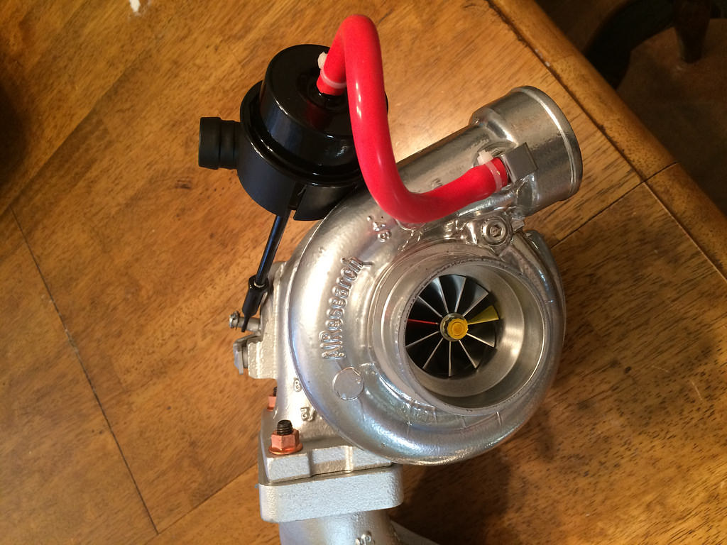
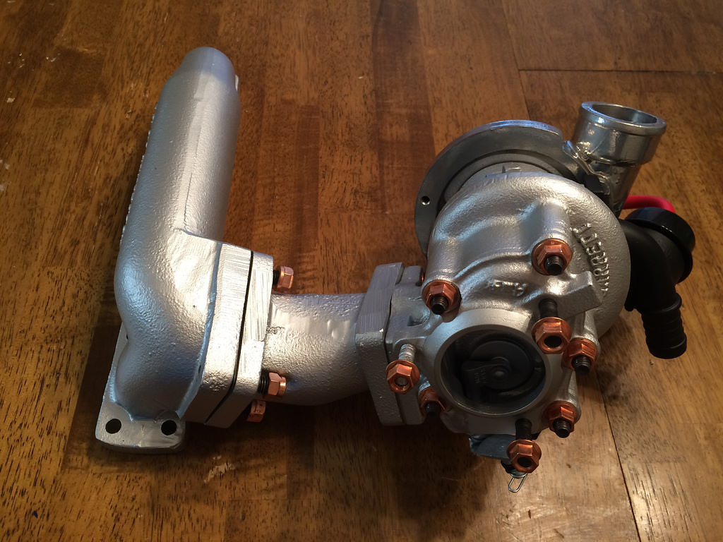
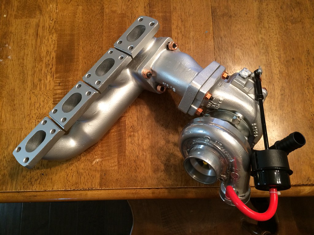
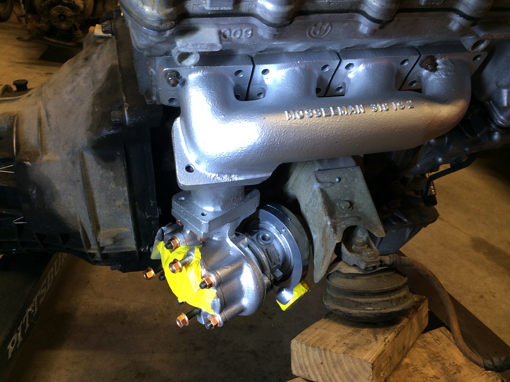
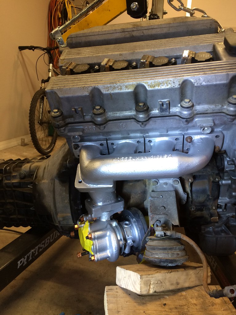
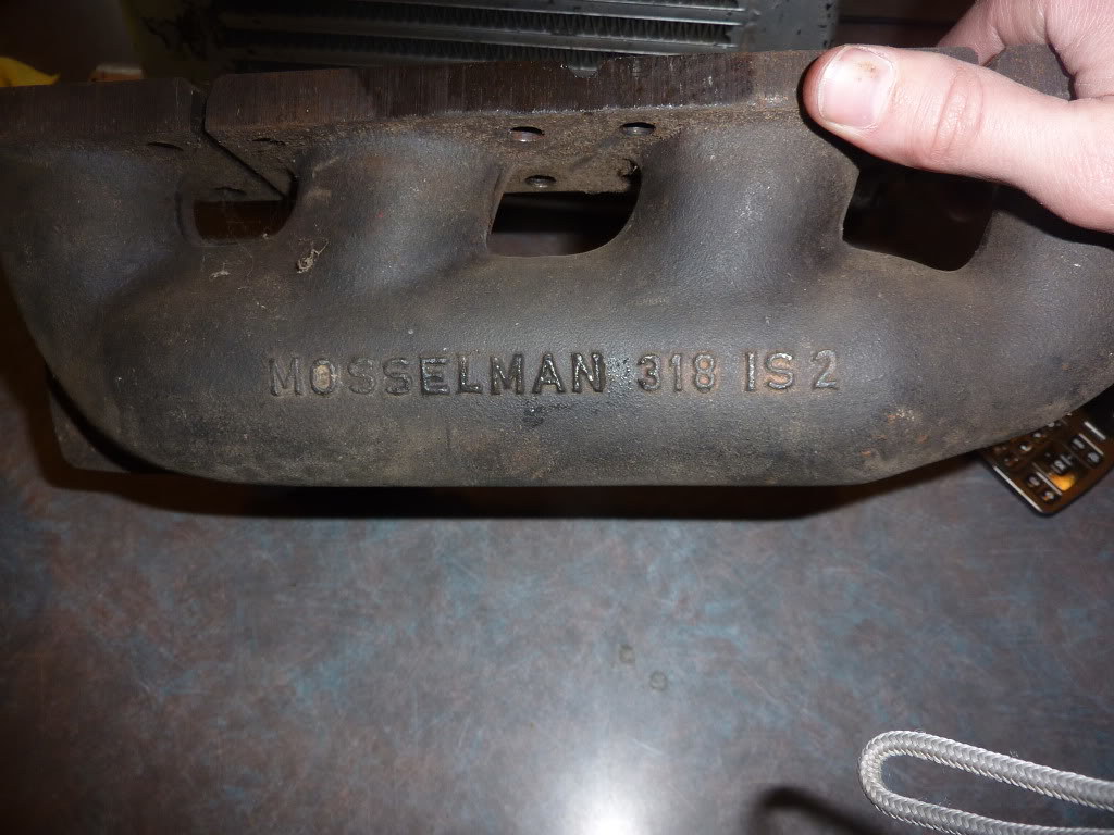
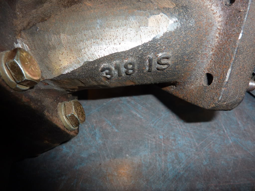
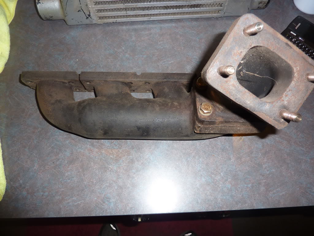
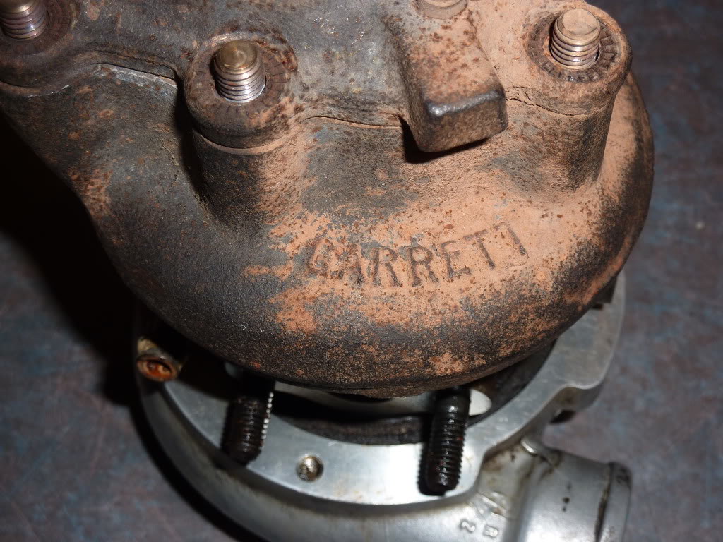
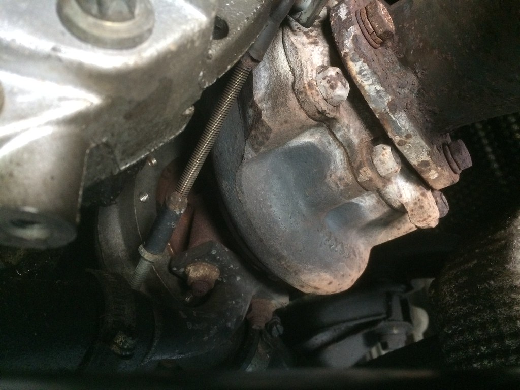
As it turns out I have been considering turbocharging this car for a while. I am still on the fence with the two major hurdles being the turbo manifold/downpipe, and the engine management solution. I think I have solved both and picked up this rare Mosselman 318iS bottom mount turbo manifold and rebuilt T25 GT2554 turbo. Both have been ceramic coated and the turbo wheels have been replaced with billet wheels and a 360 degree bearing courtesy of Gerry ad G Pop Shop.
Mosselman Cast Iron low mount exhaust manifold and adapter fully ceramic coated from an E36 318is kit
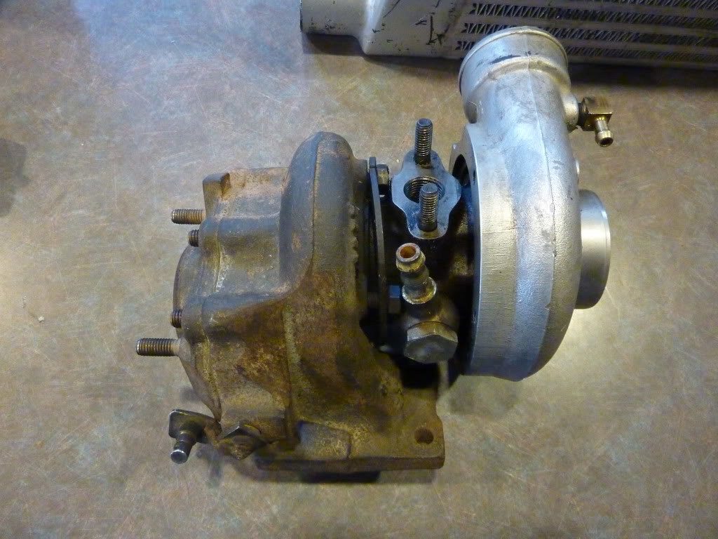
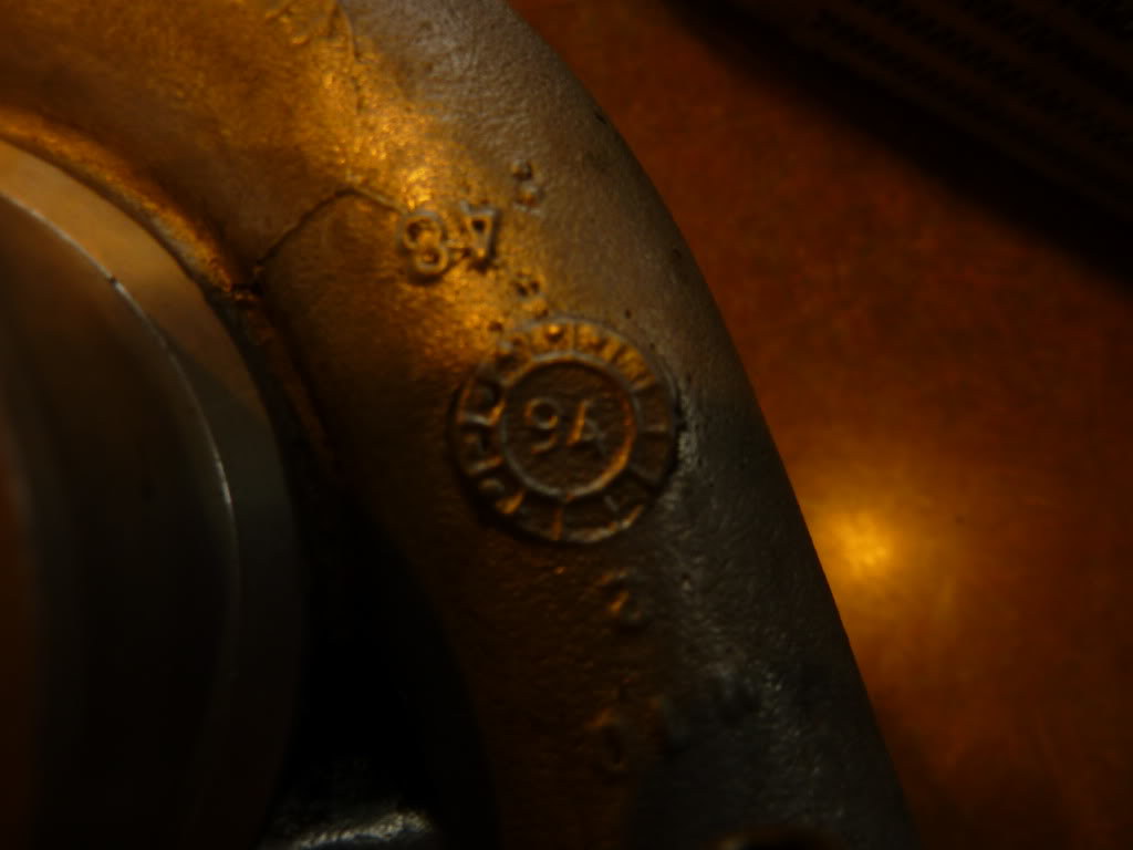
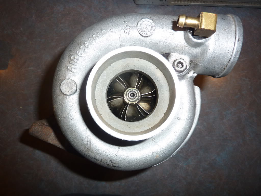
Garrett T25 turbo (turbo has just been rebuild with heavy duty internals, 360 thrust bearing and step gap piston ring) Upgraded to GTX style billet compressor wheel, flows enough for over 300HP. Compressor side .48 (but the wheel has been upgraded and there is no way to calculate the exact A/R now) turbine .49. Very responsive turbo for this application, should spool almost instantly. This turbo can be upgraded even further, if you decide that you need more at a later time.Exhaust housing and bearing housing have been fully ceramic coated, the compressor housing has been powder coated "chrome"
Internal wastegate set around 8 psi
It is essentially a Garrett GTX2554 turbo at this point. It was upgraded with the billet GTX2554R 1.658" (42.12mm) inducer and 2.1410" (54.39mm) exducer. Originally it was a much smaller 38mm inducer, that is what Mosselman had spec'd out back then. The bearings are upgraded to 360 and it has a stepped gap piston ring on the exhaust side, again all of the best parts that you can get for this turbo. The bearing housing, turbine housing, adapter and manifold was all ceramic coated and the compressor housing was powder coated chrome.
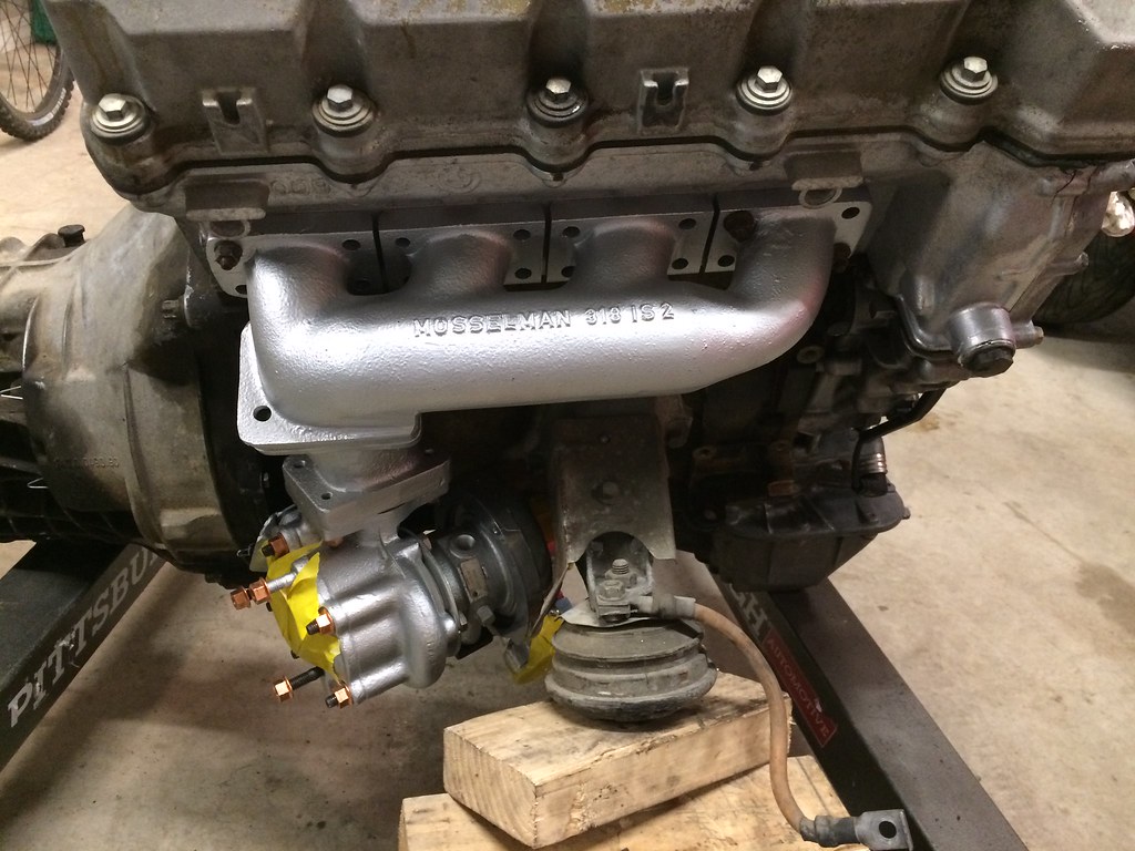
The previous owner test fit it on the car and it looks like it will fit with slight modification. Since this was for an e36, I am not sure how it is actually supposed to fit and how it changed when put in the e36 chassis or on the m44 engine. I may need to modify the engine mount heat shield, and the arm that the wastegate rotates on by the transmission.
;D
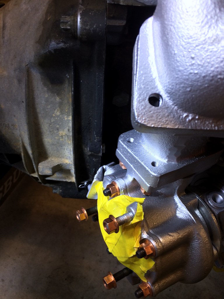


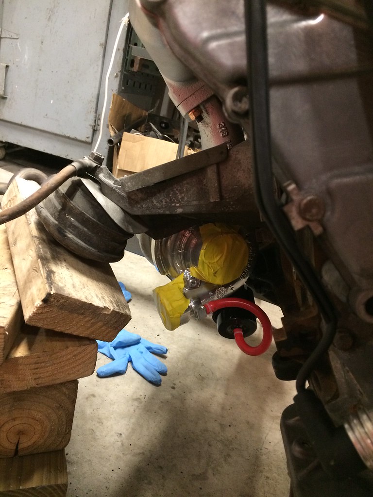
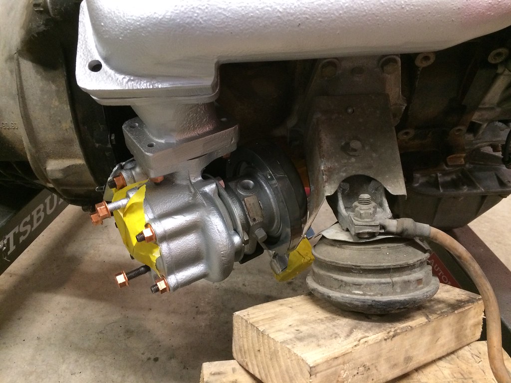
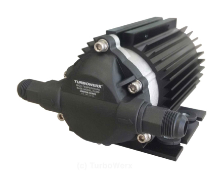
The only worry I have is the oil drain may require a scavenge pump. I looked at those today and found this Turbowerx pump. It flows nearly 2 GPM and can run dry indefinitely, only problem is it is $250 and I am not sure if it needs a surge tank or something to work. I also need to figure out where it could mount under the car; I am not sure the skid plate is the best plate for it.
The plan right now is to make an adapter that uses a spare DIY PnP for an m20 to convert it to 88 pin connector to plug into the original engine harness. I could run 42# injectors and boost this thing up to 14 psi if it takes it. Full standalone would be ideal so I could prevent knock or add a knock sensor maybe. The m20 clutch should handle 200 hp and it should be a screamer. An exhaust would be easy enough to figure out as a bottom mount. Looking at the GT2554R turbo map, this would spool quickly and pull until about 6000 rpm at 8 psi boost, depending how good the billet wheel is.
Next I need to figure out the wiring for the megasquirt to convert it to wasted spark or sequential ignition and how to convert the m1.3 wiring of the 55 pin ecu to the 88 pin wiring harness. It looks like the coil and the tps are the major differences.
Stay tuned, this will probably take place over the next 6 months.318iS Track Rat :nice: www.drive4corners.com
'86 325iX 3.1 Stroker Turbo '86 S38B36 325
No one makes this car anymore. The government won't allow them, normal people won't buy them. So it's up to us: the freaks, the weirdos, the informed. To buy them, to appreciate them, and most importantly, to drive them.Comment
-
Been waiting to see this post pop up again. I’m actually regretting selling the turbo stuff off as I’m now buying up parts again for m42 boost. Whoops. Really interested in how things work out on it all and hoping the drain doesn’t require a pump.Comment
-
In looking at those pictures, it would seem that you might be able to use a -10AN oil drain fitting with a hose that runs to the top edge of the oil pan. It would be great not to have to get the scavenge pump. It is tough to tell from the pictures, but I would suspect that if there is a good place on the oil pan that is somewhat in line, you would be ok. My M30 oil drain really isn't that vertical (something like only 20* down and forward)and I only seem to have issues in cold temperatures (<50F) before the oil fully warms up (with 15W50!).
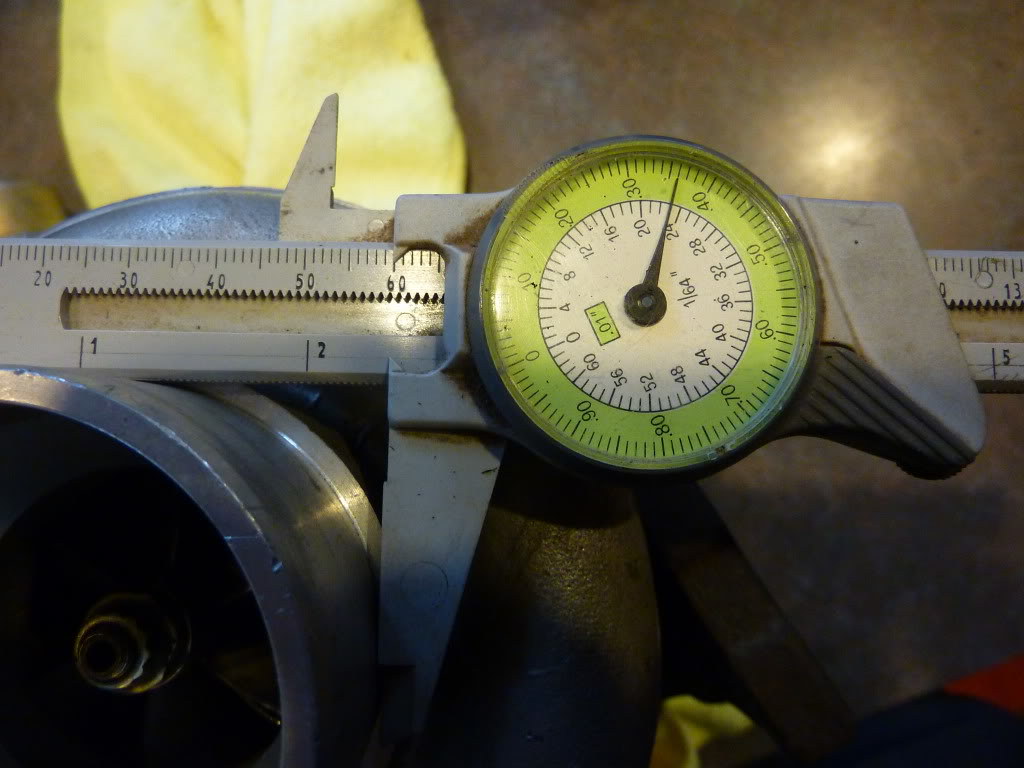
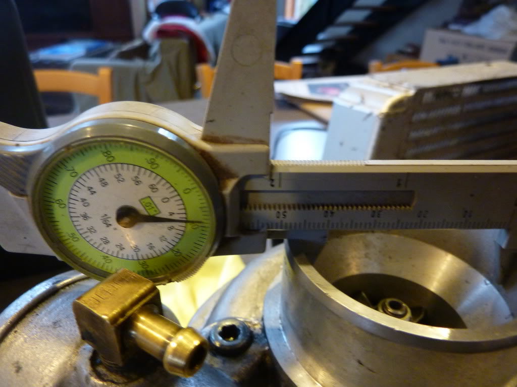
Since you have the turbo on the bench, you might as well measure both compressor and turbine wheel so you have a reference of the exact combo you will be running. This might give you the ability to compare to other turbos or make an educated upgrade decision down the road.
I'd be interested to see your compressor plot/match at 6000ft as I am not very familiar with flow of the M42.
I'm also not very familiar with the flow of a T25 turbine.
When I plotted my M30 even at 11psi, I'm only hitting max efficiency in the 4000-5000rpm range. Of course the M30 isn't known to be an engine designed to revved, so I don't really plan to go past 5500 anyway, but the M42 is designed to rev. With that in mind, as long as your turbine isn't causing extreme backpressure at high rpm and 8psi, I imagine that a turbo paired with the high revving design of the M42 would really scream above 5000rpm. My M30 at 6psi and a longer diff is still faster than S38B35 in the revs...
The advantage of the log manifold is that you keep more heat in for the expansion of the spent charge. It isn't equal length or perfect for max overall power, but for low boost setups of say 8-10psi, logs seem to work pretty good. The ceramic coating will only help.
I also think long manifolds have less tendency to crack, especially if they are not welded. Yours being cast, again is a plus. The turbo hanging down rather than up and out also helps on a track car where there will be high Gforces. The turbo will be tucked down lower and won't be cantilevered out and on a manifold prone to as much flexing/swaying/twisting as a topmount turbo manifold with a long moment arm.
Originally posted by captain awesome View Post
I seem to be doing the same thing with my M30 as the turbo manifold is the hardest/most expensive part to get and I just acquired another to go along with my turbo e24.Comment
-
Originally posted by tschultz View Post
I had been searching and found some interesting info on this t25 turbo, some info in the links I have 2 posts above. Basically this is what I found for the T25 and DGerry said it originally came with the 38m compressor wheel inducer.
This compressor comes paired with a housing A/R of 0.48.Hey Dougal you pulled through, thanks. O'kay, so is this to say that any T-25 A/R=.60/.46 will perform within this mapping? So if us novices were to call up a turbo spec. shop with this mapp they would know which turbo to sell us? You mentioned turbine size. What turbine size is right for the 3B application? Well done, this post should be sticky'ed.
The compressor wheel comes in two "trims". The trim refers to the ratio of wheel diameters (small^2/big^2).
The 60 trim wheel is 51.3mm od and steps down to 40mm at the intake.
The 55 trim wheel is also 51.3mm but steps down to 38mm at the inlet.
But the differences in the maps are minor for this application, either will do.
The turbine can vary, some will be 0.49 A/R and this is the one you want. Others will be 0.64 A/R which will still work but won't boost as soon as the 0.49.
These numbers are cast into the turbine housing (hot side) by the neck which bolts to the exhaust manifold.
I think the closest turbo in the current garrett GT range would be the GT2052.
TurboByGarrett.com - Catalog
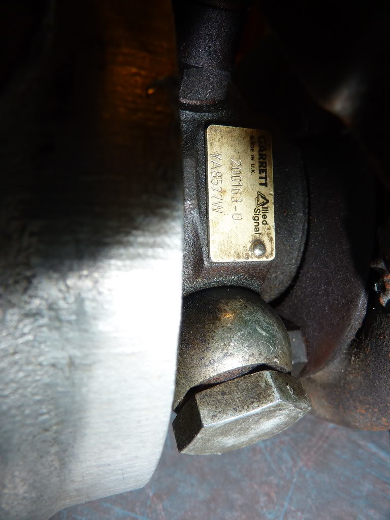
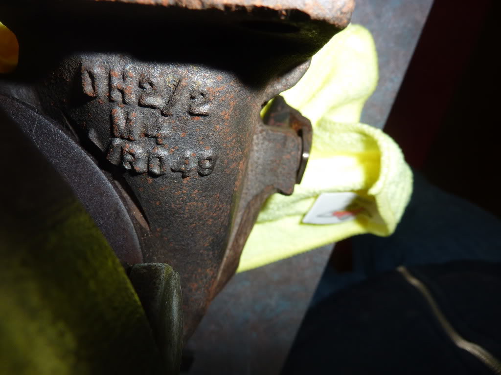
This would put the original AiResearch turbo as a 55 trim turbo. One of the links above has photos of the original 318is mosselman kit so I reuploaded them to save and compare. I think this was on an e36, but am not sure. I don't see anything resembling a scavenge pump so I assume it didnt use one.
Intercooler end pipe diameter
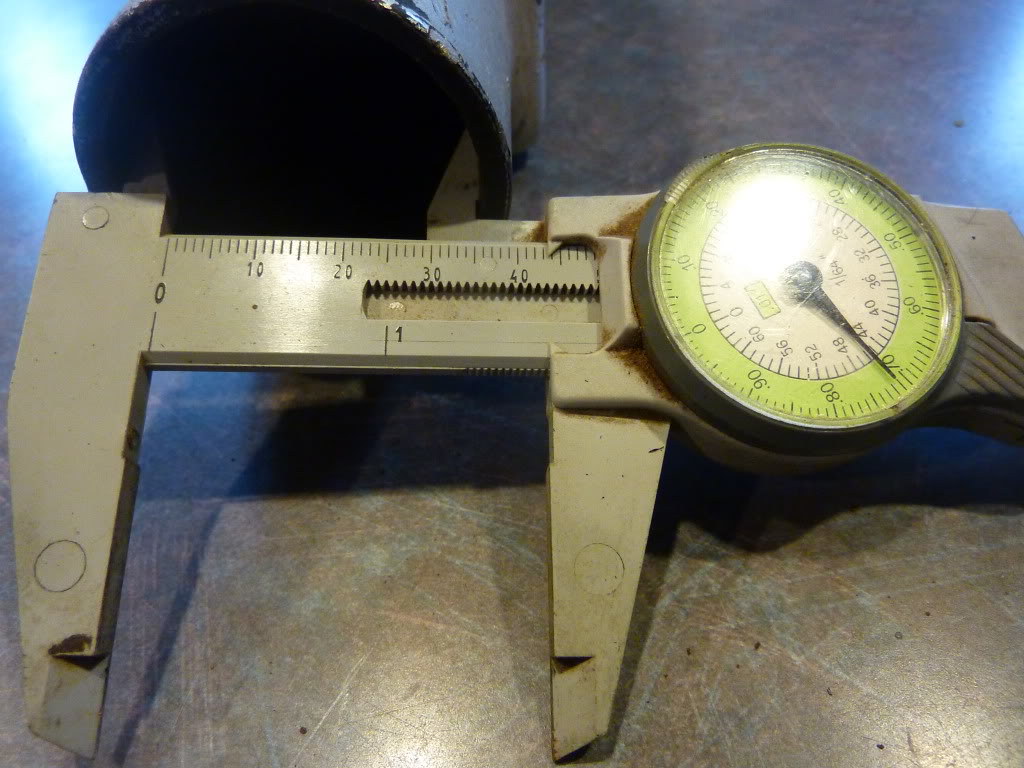
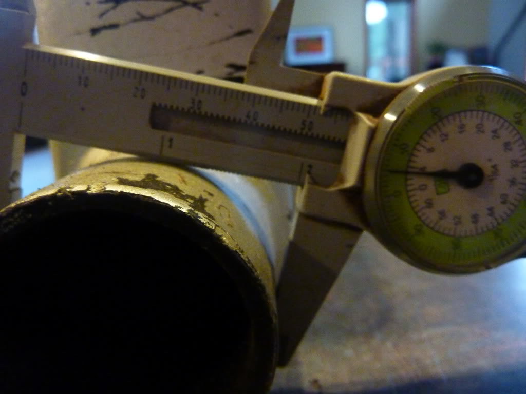
compressor inlet diameter
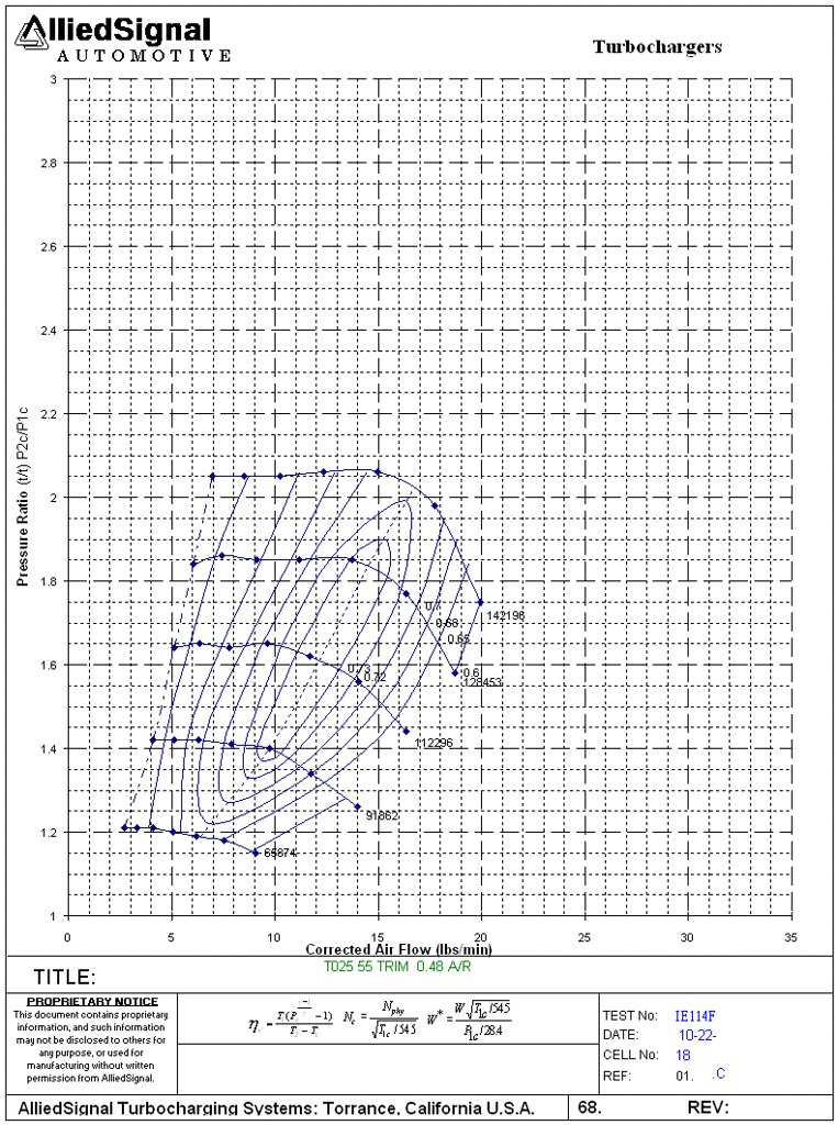
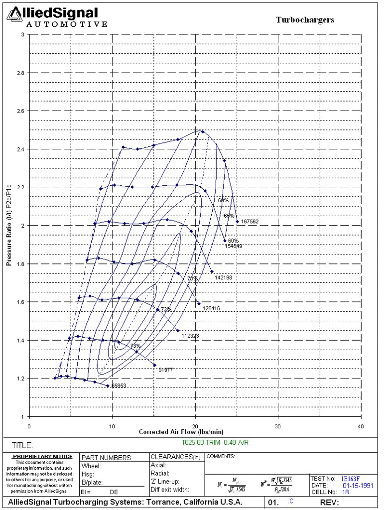
The original mosselman setup, if the above is true, ran a 5.5 psi intercooled setup with a T25 55 trim. It made about 180 hp over the stock 137 and started building boost at 1200 rpm with an adjustable wastegate rod. All of that seems to match what is seen above. It is a wonder many of these sold if they cost a few thousand and only gave a 30% increase in power.
This is the original compressor map for that turbo, notice the Allied Signal name seen on the turbo tag above and the compressor map below. That would put it at a pressure ratio of 1.4 and 12.8 lb/min at 4000 rpm right in the efficiency. Then it would be off the map by 5000 rpm at 16 lb/min. and up at 100,000 RPM. Probably not the best turbo for the application but definitely a compact unit to make it all fit in the tight engine bay.
Here is a thread talking about the design flaws of the original T25 turbo where they weren't designed to push a pressure ratio of more than 2 before the bearing would fail. This makes me feel better with the upgraded bearings in this rebuilt unit.
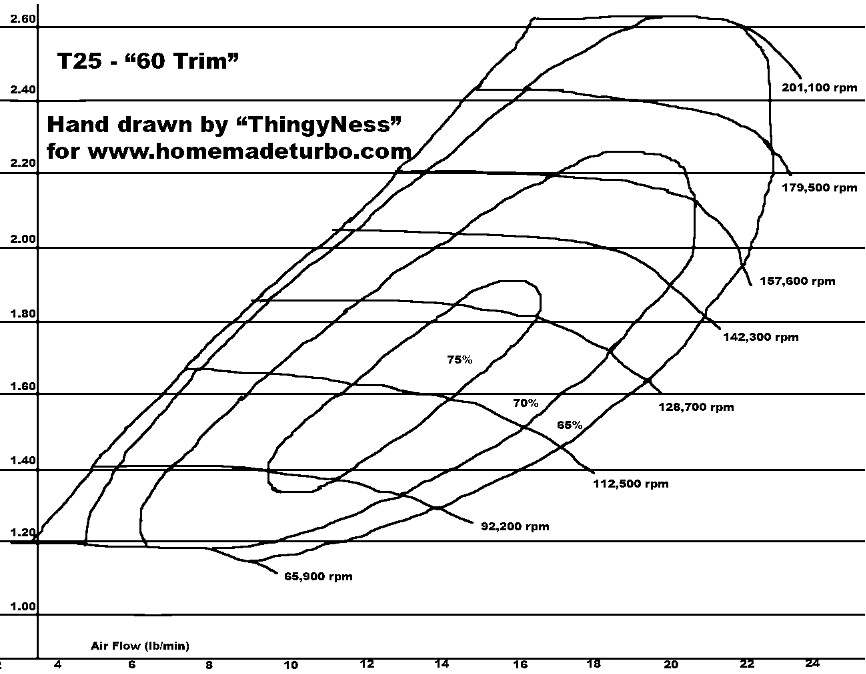
T25 - 60 trim.
Flows much better than the 45 trim (upwards of 330cfm), but watch the wheel speed as the pressure ratio goes up! At 23psi at the compressor outlet, it's spinning ~200,000rpm! For those of you using map sensors in your intake plenum and such, that may be closer to like 18-19psi at the plenum. It's no wonder the bearings in the DSM T25's disintegrate when run at higher boost levels (although the DSM T25 is a 55 trim, IIRC, its map is close to this one)
EDIT: I took apart a DSM T25 i had kicking around - it's actually a standard Garrett 60-trim T25 wheel with a 1.57" inducer and 2.02" exducer, so this flow map should be the one you're using when doing calculations with a DSM T25.
I think this is the 60 trim map he is referencing and he hand drew a crude version probably before he found the official map. This would be the compressor map I would use, but this does not show the improvement that the billet wheel would add. It is definitely a better match with just a 2 mm larger inducer on the compressor wheel. This turbo can run a higher pressure ratio and is better when increasing boost from the wimpy 5.5 psi up to say 8, but it still runs out of flow at a relatively low 20 lb/min. Over the 16 lb/min that is a 25% improvement.
compressor maps found here and here

Then we get to a couple other maps. The is just for comparison, but it was mentioned in the quote above about a comparable turbo the the T25, which is the GT2052. Here are some specs, just looking at how the upgraded wheel flows with approximately the same compressor size. Definitely a huge upgrade from the T25 55 trim.
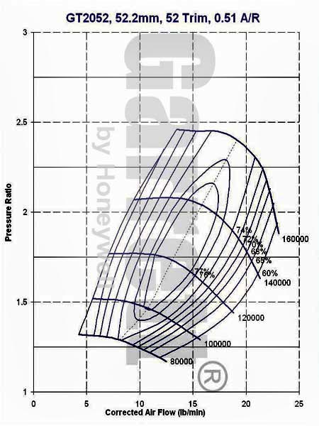
Lastly, I looked at the GT series which is ball bearing with billet compressor wheel. The GT2554R is the direct replacement for the T25 60 trim with the same specs, just running ball bearings and a newly designed wheel. It shifted the graph to the right so it flows better. It works best with a PR between 1.5 and 2.1 and flows well up to about 22 lb/min. If this is similar to my turbo then it should be able to make good power up to about 6000 rpm on an m42 at a PR of 2. Since the turbo I have hsa been upgraded, it has the same 54 and 42 mm compressor wheel size that this GT25R has.Code:There are many different verions of the Garrett GT20 turbo. There are two different model numbers that I am going to show here with the only difference is that the turbos have different mounting angles. But everything else is the same. Model: 727264-1 and 2 CHRA: 451298-43 Bearing: Journal Cooling: Oil Compressor Inducer: 37.6 mm Exducer: 52.2 mm Trim: 52 A/R 0.51 Turbine Wheel: 47.0 mm Trim: 72 A/R: 0.50 Wastegated
The Garrett GT25R or GT2554R turbocharger is the smallest Garrett GT turbo that have Dual Ball Bearings. This GT turbocharger is a popular choice because of that. The GT2554R turbo is internally wastgated also so there is no need for you to put out extra money on the fabrication of manifolds for an external wastegate setup. The turbo exhaust flange for the GT25 have the common T25 flage so it's a very easy job to bolt it on to you're existing stock manifold. This means the GT25 turbocharger is a great upgrade for many cars originally equipped with T25 & T28 Turbos. This includes cars like the 300ZX & SR20DET 240SX and many more.
The dual ball bearing GT25 will give you a very quick spool, even on a very small engine. And also give you a solid 200 WHP power figure without even breaking a sweat.
The Garrett GT25 turbocharger will work well for engines between 1400cc and 2200cc and will give you 270 HP in the engine. And that means you still have well over 200 WHP left at the wheels. The GT2554R will work well also if you are looking for 170 HP.
Model: 471171-3
CHRA: 446179-24
Bearing: Ball
Cooling: Oil & Water
Compressor
Inducer: 42.1 mm
Exducer: 54.3 mm
Trim: 60
A/R 0.80
Turbine
Wheel: 53.0 mm
Trim: 62
A/R: 0.64
Wastegated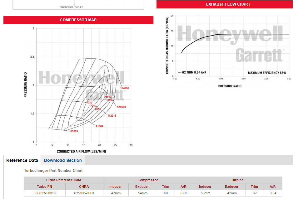
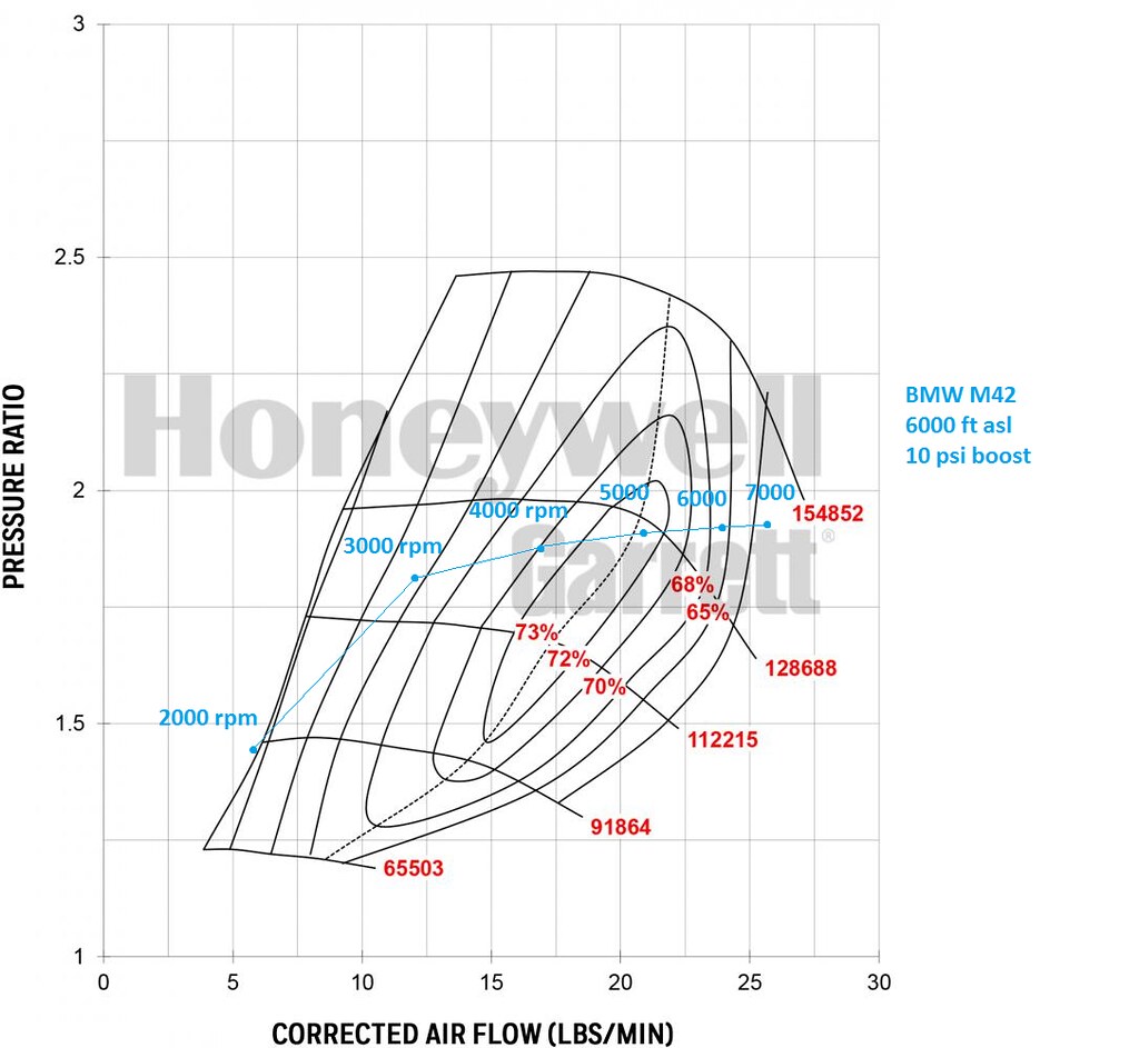
Here is my plot from some basic data i put in borg warners match bot assuming I run 10 psi at 6000 ft and mapping it on this turbo. The only difference should be journal vs ball bearing. That would be about 200 hp and 200 ft/lb torqueand it only nears the choke line above 6000 rpm and nearing 7000 where the m42 starts to run out of steam. I think the adjustable cams could be change to shift the powerband higher without losing the low end torque due to the quick spool of the turbo. I'm getting pretty excited about this since it looks to be sized about right, boost should be between 3500- 6000 rpm at my altitude. At sea level this same boost and setup would be about 230 hp/224 tq with aPR of 1.7 and flow of 24 lb.min right at the choke line at 7000 rpm.
http://www.turbos.bwauto.com/afterma...6_wrsin=92044& this is the matchbot data I put in for the m42, ignore the map on the borgwarner website, and look at what I plotted out here.
Here is some info I found on turbines. Essentially the compressor A/R does not really affect spool up much, but turbine A/R does (makes sense). Supposedly the T25 was used on the 3.4L turbo diesels on the Ih8mud forum and they recommend the t25 as a perfect match for those engines. They make max torque on the 3B engine at 3500 rpm, so with an engine half the size revving to twice the rpm, would be a pretty good fit(1.7L at 7000 rpm) and the m42 is just slightly larger so that is where I hope the billet wheel will pick up the difference in engine size.

erminology
A/R
A/R is a numerical rating assigned to radial flow housings in order to distinguish the relative volumetric flow capacity of the housing. A/R does have units of length (inches or cm) based on the "A" over "R" description. One must be careful because the A/R values can only be compared within a single family of housings. 0.86 A/R of a GT28R and a 0.85 A/R of a GT40 have very different flow capacities. The term A/R is derived from:
Q = volumetric flow rate
A = cross-sectional area of the volute at the tongue
R = radius to the dynamic center (The dynamic center locates that point which divides the scroll area such
that half the flow passes above and half the flow passes below the dynamic center.)
V = tangential component of velocity
Q = A x V (where V = K (flow rate constant) / R)
Q = A x K/R
Q = K x A/R
Since K is a constant then A/R defines the flow capacity of hsgs within the same family.
Compressor A/R - Compressor performance is largely insensitive to changes in A/R, but generally larger A/R housings are used to optimize the performance for low boost applications and smaller housings are used for high boost applications. Typically there are not A/R options available for compressor housings.
Turbine A/R - Turbine performance is greatly affected by changing the A/R of the housing. Turbine A/R is used to adjust the flow capacity of the turbine. Using a smaller A/R will increase the exhaust gas velocity into the turbine wheel, causing the wheel to spin faster at lower engine RPMs giving a quicker boost rise. This will also tend to increase exhaust backpressure and reduce the max power at high RPM. Conversely, using a larger A/R will lower exhaust gas velocity and delay boost rise, but the lower backpressure will give better high-RPM power. When deciding between A/R options, be realistic with the intended vehicle use and use the A/R to bias the performance toward the desired powerband.Also a good doc on turbo water cooling.A/R doesn't change the flow linearly, it's a square root relationship. So if you half the A/R you change the max flow by about the square root of half or 0.7.
If I divide the exducer flow area by the square root of the A/R I get a consistent number across all turbines of similar size.
As the turbines get much larger, this number drifts a bit smaller. But the trend is very good and easy to follow.
Upshot. I can predict max flow and the rough shape of a turbine map from the turbine exducer and the housing A/R.
So for the HE221 or TD04HL with a 6cm housing (same thing) we have an exducer of 45.6mm and an A/R of 0.5.
The max corrected flow is expected to be ~14.7 lb/min which is just a fraction bigger than the Garrett GT22 (14.2lb/min), significantly bigger than the 0.49 A/R T25 I'm running now (approx 13.3 lb/min). But approx 10% smaller than the 0.64 A/R T25/T28 I had run for a while.
In short, it is the size I hoped it would be.
A few other m42 turbo threads for reference. It sounds like most other bottom mounts needed a scavenge pump.
bottom mount
bottom mount
crazy build
Last edited by downforce22; 02-15-2018, 07:55 PM.318iS Track Rat :nice: www.drive4corners.com
'86 325iX 3.1 Stroker Turbo '86 S38B36 325
No one makes this car anymore. The government won't allow them, normal people won't buy them. So it's up to us: the freaks, the weirdos, the informed. To buy them, to appreciate them, and most importantly, to drive them.Comment
-
sub'd to this thread. Always excited to see another turbo m42. Like we talked about I am a fan of the bottom mount manifold you have. Looking at the way Todd did his bottom mount another idea you can do to prevent an issues with the oil drain is to ditch that adapter piece and in exchange cut a wedge piece to swing the turbo out from the block on the original flange then you can run your intake pipe up above the engine mount and your outlet pipe under the engine mount. Then you can put the drain to the oil pan up front like everyone else does and you shouldn't even need a scavenge pump.
Also it being a bottom mount T2 style manifold I highly suggest getting these tabs from Nissan. I've had a couple friend have their turbos basically fall off because they didn't put these back on their sr20's.

Comment
-
That compressor looks really good...
Even at 8psi, you are right in the efficient spot of the compressor. Even at 8 psi on that engine, it would be plenty powerful and maybe retain a bit of reliability. I know my M30 transformed with the turbo in terms of usable torque as well as overall max power.
If anything, I wonder if the smaller AR turbine housing will limit overall flow (obviously with a trade off of excellent response). Since the M42 is low on torque at lower RPM, this may be a fair trade off. You might have instant response and still good flow with the 4 valve head design...
In my thinking, the turbo on the M42 will also be better than say S50 or S52 because you retain the lightness of the M42 but you don't have the same power loss at altitude. I imagine it will be an even better autocross car than it already is, due to the ability to accelerate.
What do those tab do? Locking the compressor/turbine housing bolts tight? Only one of my 3 turbo's have those...Comment
-
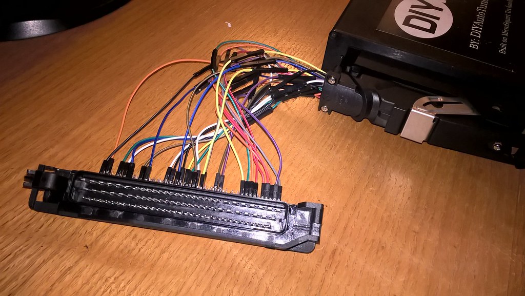
I've been researching to get the running on megasquirt and after finding an 88 pin socket, I put together a pinout of the 55 pin diypnp unit and compared it to the 88 pin unit of the m42.
A few differences include:
- 2 wire ICV vs 3 wire on m20
- 4 coils instead of a single coil
- vtps already installed vs switch style
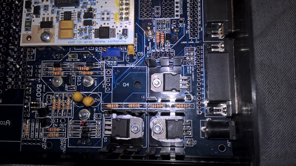
Seeing that,I figured it would be possible to adapt the 55 pin to the 88 pin myself. I was trying to figure out how to make in case I made a mistake during the pinout process and then my friend showed me ribbon cable withpin that would fit right on the end of the adapter board. So I started wiring that together. This is how it looked after my first attempt.
In order to make this work I had to make a few assumptions/ changes to the circuit.
- Added 1 BIP373 driver to make a total of 4
- Added 100 ohm resistor in R1 slot for this BIP driver
- Added pin 19 ignition ground which was not on the circuit
- Replaced 2 cut xener diodes, one was on the main relay circuit
- Added S4 spark output for last BIP driver
- Jumper IGN pins to s3 and s4 for wasted spark like this picture
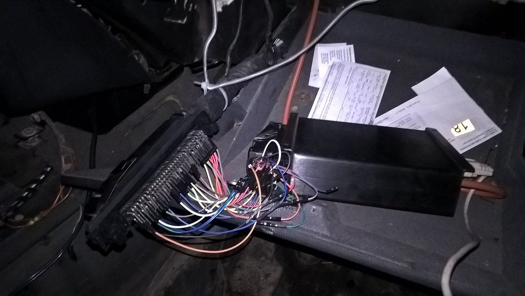
I plugged it in and verified base timing settings. TPS was working so I tried to start it with the narrowband oxygen sensor. It kept sumbling and backfiring and would sort of run. I ran back through my settings and checked my spark output wiring and it seemed good. So I opened up the ms unit again and traced lines. As it turns out the injector banks were pinned backwards on the circuit. So I swapped those two pins on my circuit adapter and went back to try it. This time it started and ran a little rough without any fuel or spark settings dialed in.
The idle valve and coolant temp was not working. So last night I reviewed the pinouts and tried swapping wires. This just caused the tps not to work. Last night I ran through the grounds and the m42 has one additional ground over the m20. I realized I hadn't connected pin 43 to a ground so I ran a jumper from m42 43 to m20 43 to ground and tried it today. I got it running decent and even idling on its own without the ICV. Base timing is around 16 degrees and fuel seemed steady. Click below for crappy idle video
 WP_20180310_17_12_21_Pro
I need to figure out why my coolant sensor only reads 180 F and why the ICV does not work. It also isn't super happy revving but that may just be a fueling issue since I don't know how rich or lean the mixture it. I've been talking with Ccsdo5 about this and will try swapping the coolant to iat sensors to see if the wiring works and maybe just the sensor is bad. same thing with the 2 wire ICV as maybe I just need another wire to the 'close' port on the ms unit instead of the 'open' wire. With those couple things figured out I just need to wire in my afr gauge to dial it in. Maybe I will do that tomorrow to see what is really going on with the engine. In the mean time here is a neat 1947 Plymouth I parked next to this morning.
 Last edited by downforce22; 03-11-2018, 08:19 PM.318iS Track Rat :nice: www.drive4corners.com
'86 325iX 3.1 Stroker Turbo '86 S38B36 325
No one makes this car anymore. The government won't allow them, normal people won't buy them. So it's up to us: the freaks, the weirdos, the informed. To buy them, to appreciate them, and most importantly, to drive them.Comment
-
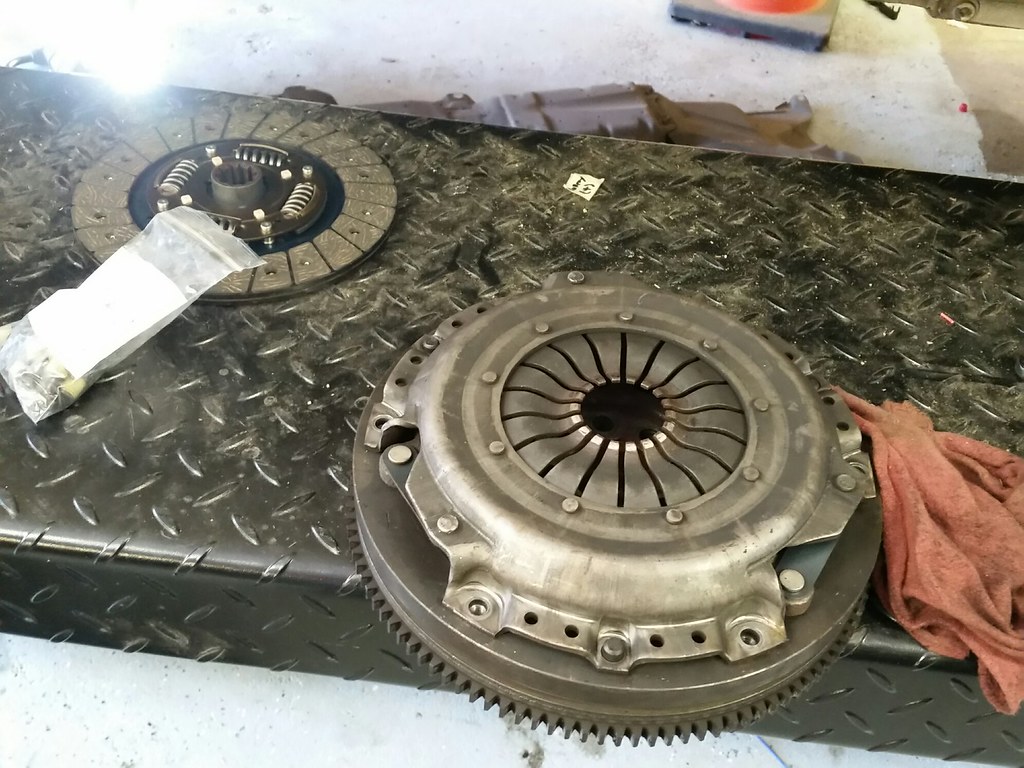
Made a big step forward this weekend with the m20 clutch swap and lightweight flywheel.
I had picked up a 10 lb m20 flywheel for another project and ended up not using it. I grabbed a sachs clutch and pressure for the m20 and got all necessary parts like the m20 starter, shorter flywheel bolts, pilot bearing, and throwout bearing. While I was in there I grabbed a few parts to refresh the shifter as well. The flywheel has been lightened and weighs under 10 pounds. It also cleared the bolts and didn't need a spacer because of the material that had been removed on the back side of the flywheel
BMW 325 325i e30 ultra light flywheel
9.6lbs baby! That's almost 10lbs lighter than OEM!!! Hellacious impact on 1st and 2nd gear acceleration. Significant impact in 3rd gear acceleration, and detectable impact in 4th gear.
I race BMW 325's (e30). When my car reached end-of-life last Dec (87mph into a cement wall) I started shopping for a replacement. I ended up finding a car that had been prepped for a different race class. This ultra-light flywheel came with that e30 race car. It was legal for the other guy's race class, but not for mine, so I had to remove it. That is to say.... the lightened flywheel is such a significant performance enhancement that I'm not allowed to run it.
The flywheel is 3yrs old but has only 2 race weekends on it. It's friction surface is absolutely perfect. I did some bead blasting on it, avoiding the friction surface, in order to make the flywheel a little prettier.
This is an OEM steel flywheel that was custom machined to remove steel where it matters the most, yet retain enough steel to be as strong as it needed to be. It's the lightest steel flywheel you are going to find for an e30, yet was strong enough to race with.
Shipping is $20 to CONUS, $30 to AL, HI, Canada, and MX. Shipping outside of N. America will
have to be worked out after the sale.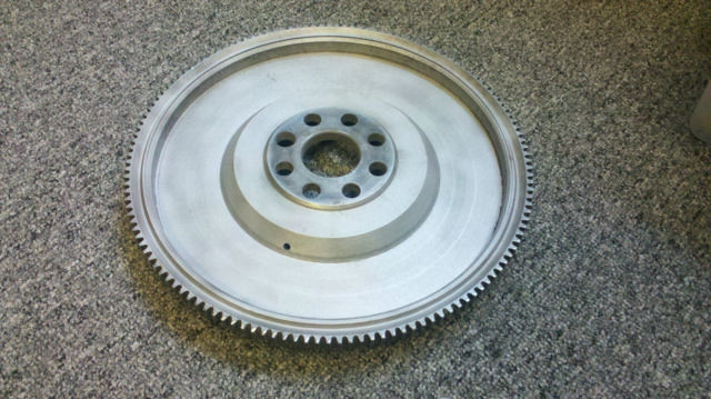

Above shows a stock m20 flywheel vs this flywheel and you can see the weight difference. Below is the old clutch and flywheel. The net difference in weight is about 10 pounds lighter with a heavier duty pressure plate and clutch disc.
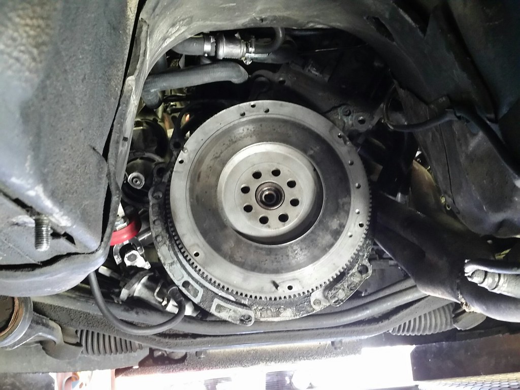
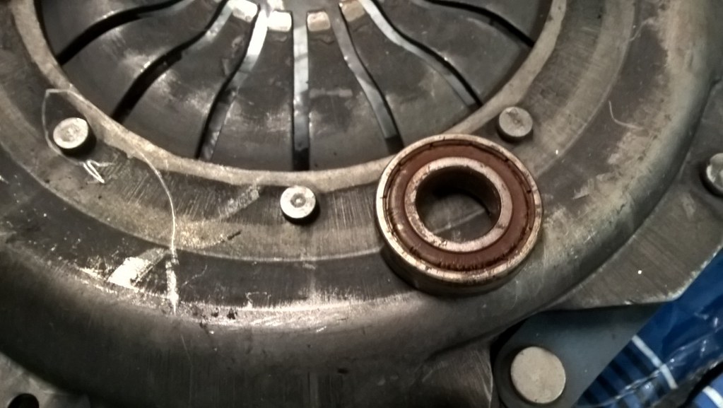
The old pilot bearing was toast and just fell out of its home.
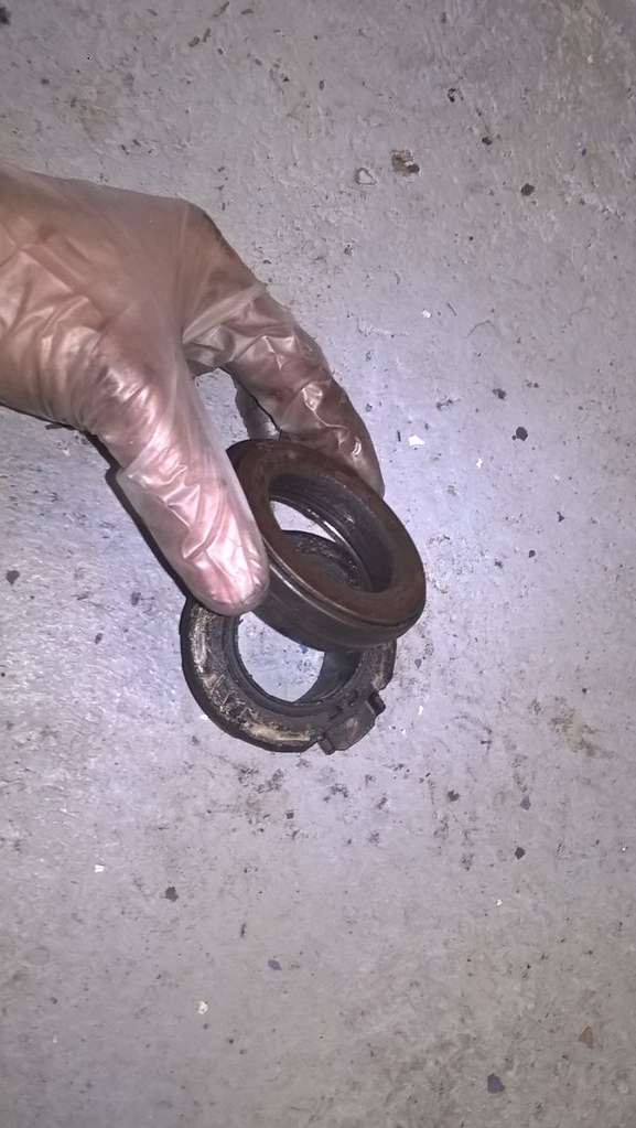
The TOB had seen better days as well.
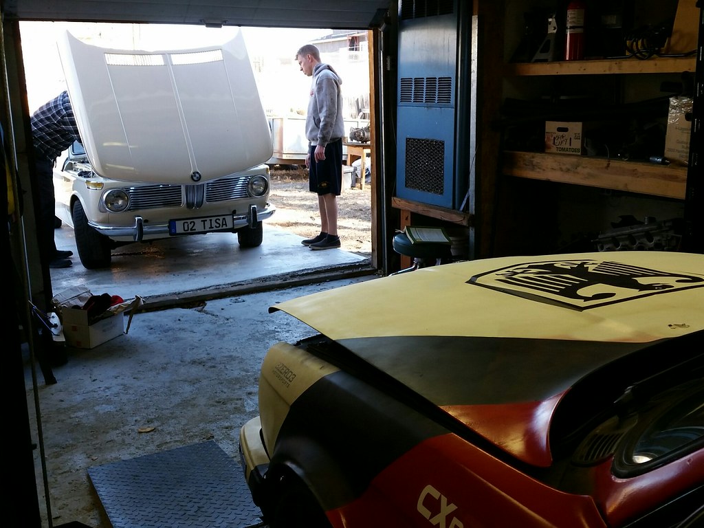
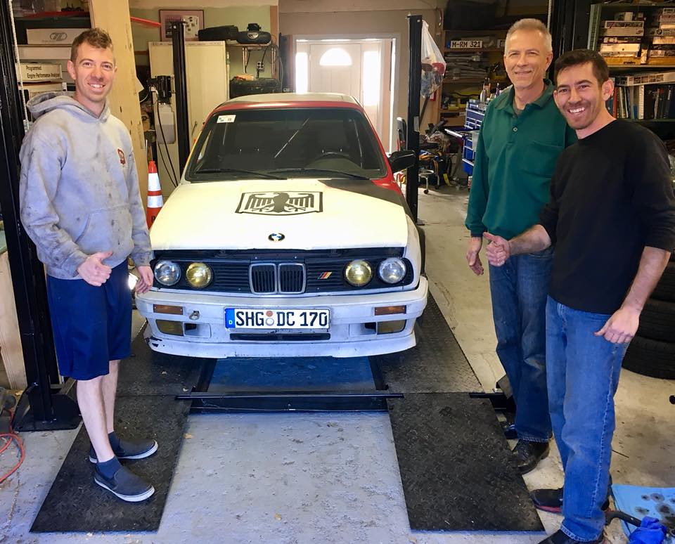
My friends at 1017 were kind enough to let me use their lift for the job. Its a great place to do work on a car.
I had to rep them with a decal.
So after getting it all back together I went to start it and after firing it sputtered out. I thought maybe it was a vacuum line that had come off the idle valve, but after looking at it, nothing seemed to be wrong with the vacuum system. I realized the fuel pump was not buzzing like normal so I followed the line and found an inline fuse that had looked burnt and figured that was the problem. I removed that and tested it again and it still would not start. I remembered that the fuel pump was powered with a wire going by the drivers footwall so I jumpered it to the C101 and got the car started. Since it was near the end of the day, I wired the pump to constant 12 v and drove home. On the way home, I noticed the power windows and HVAC fan did not work.
That made me realize the circuit for the power windows was not getting power as well as the HVAC circuit. If the fan worked on high i would have known it was the resistor that was causing the fan problem but this didn't work at all. So after a night of sleeping on it I remembered the m20 starter I was using had one less terminal on the starter solenoid and I didn't switch it over from the m42 starter so one wire was not connected on the new starter.
So I pulled out the chilton manual and started looking at circuits. It looked like the power windows and hvac were getting power from the relays. I realized my fuel pump had been wired in to the fuse for the power windows with the 30 amp switch. Next I started to look at the forums and found this thread which prompted my search for starter differences and the unloader relay.
And this thread seemed to describe my problem exactly.
So i went out and grounded the extra wire on the stater and that solved both problems for the window fuse, and the hvac fan. With that fixed i could get back to actually testing the car with the new setup.

The gear shift is nice and tight and really slides into gear nicely. The next thing I noticed is that the clutch pedal is a little heavier, but it is still easy to drive. The engine is a bit more free revving and makes the car feel more lively. It isn't any faster but it is more lively at changing rpm and isn't lazy on downshifts like the heavy dual mass unit. It is now more awesome to drive. Here's one more picture after a job well done. Next up is timing chain/components and standalone fuel with the megasquirt unit.
 318iS Track Rat :nice: www.drive4corners.com
'86 325iX 3.1 Stroker Turbo '86 S38B36 325
No one makes this car anymore. The government won't allow them, normal people won't buy them. So it's up to us: the freaks, the weirdos, the informed. To buy them, to appreciate them, and most importantly, to drive them.Comment
-
-
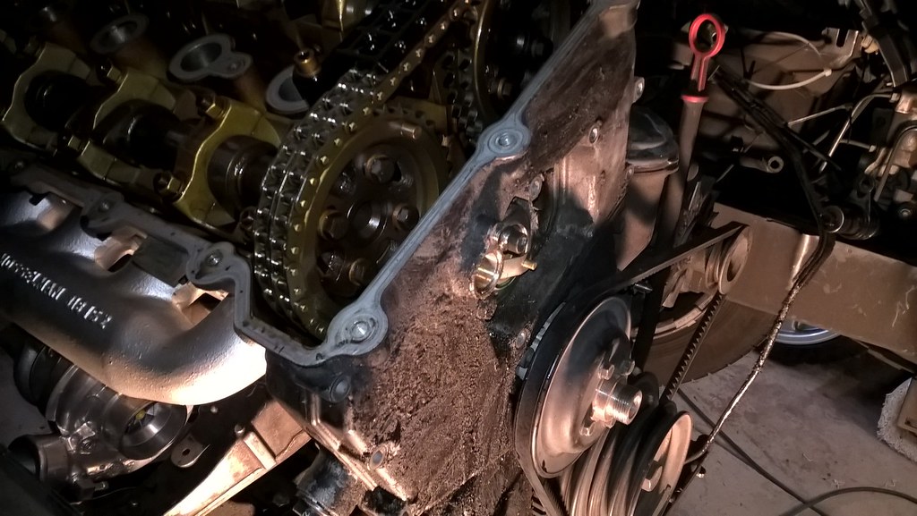
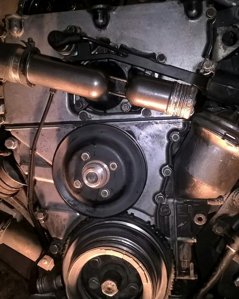
This m42 underwent a lot of work recently. Since the car had no history or records, I was worried that something might go wrong soon. The water pump was seized in the motor and I had put 16,000 miles on the engine alone with some 212,000 at the last report in 2012 or something. I ordered new timing guides and found some used cam gears since the original cam gears are NLA. I had stashed these parts away last fall and was waiting to take on the project. In late april the exhaust on my car seemed to crack open before the resonator so it started to sound like a tractor and I realized it was a good time to do the work.
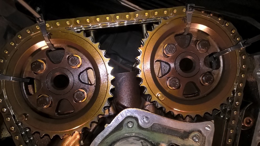
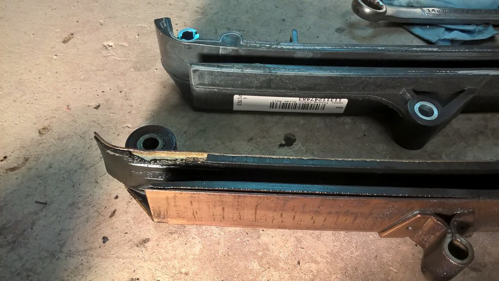
I tore into the engine and got a good look at what was going on. Here is a picture showing the grease on the front of the engine.
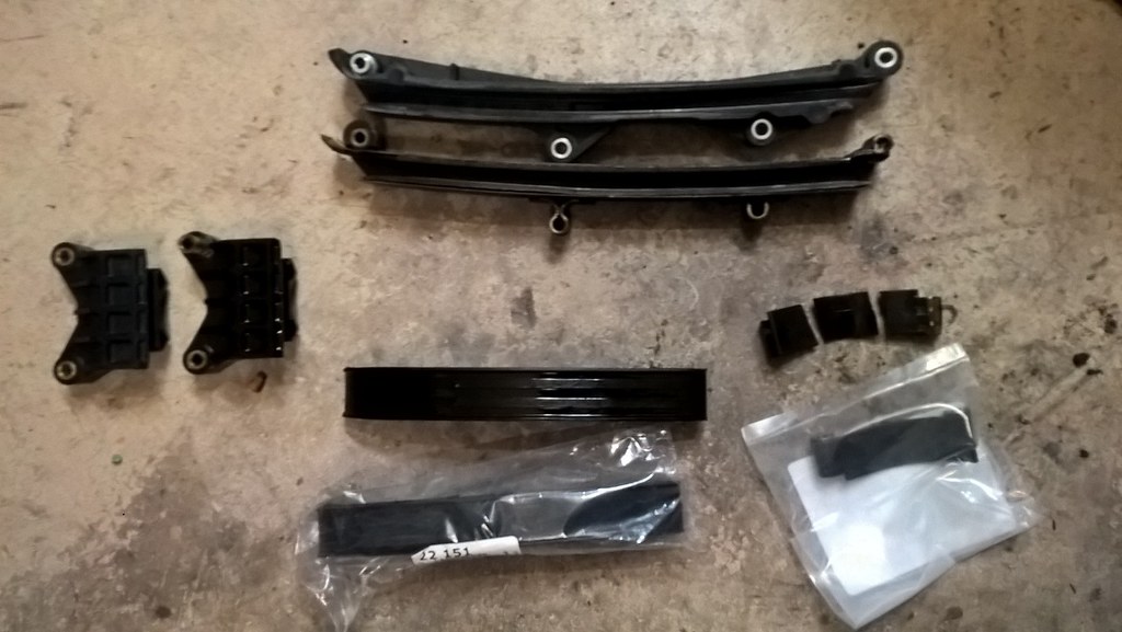
After it was opened up I found one broken guide.
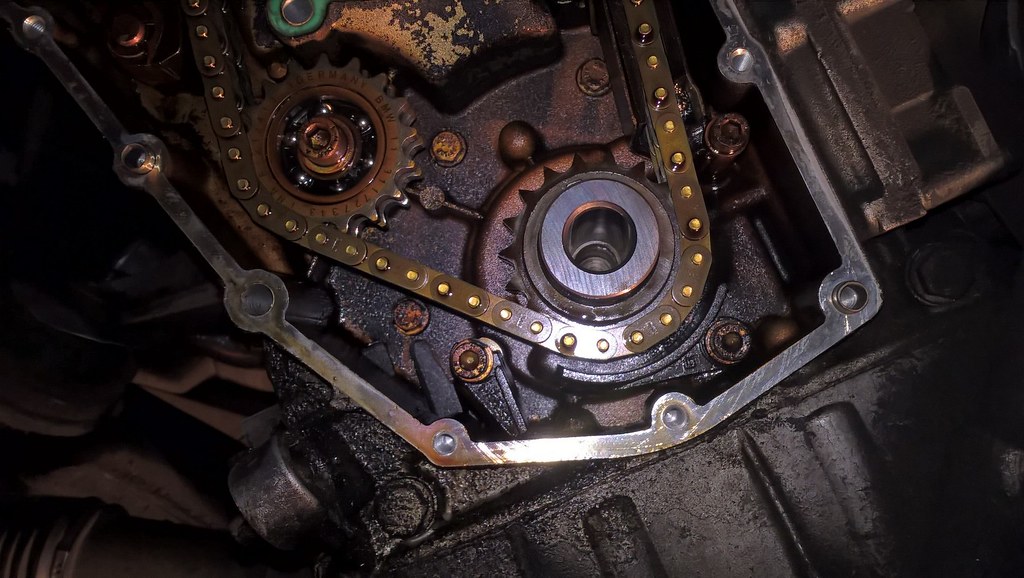
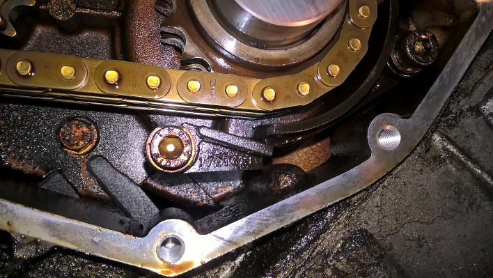
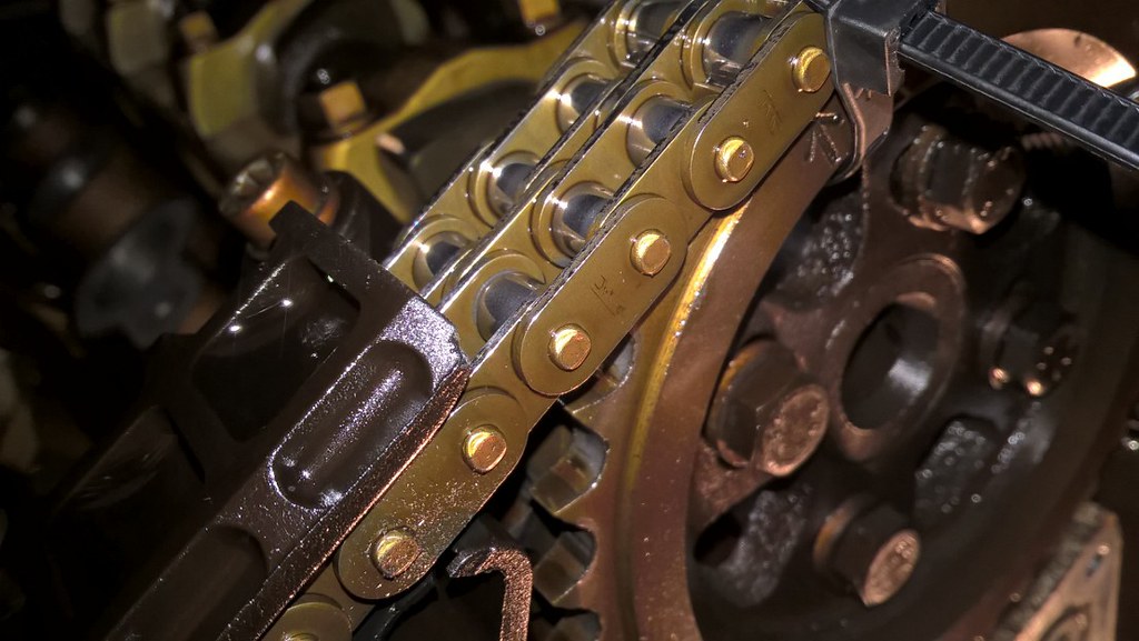
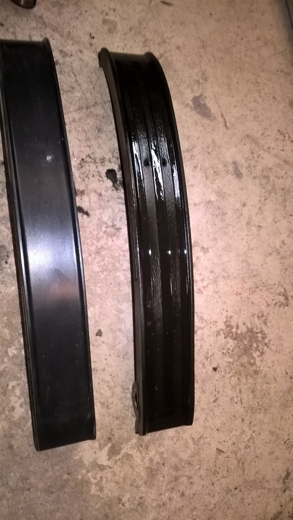
The top rail had these grooves from the chain, the new one didn't have any grooves.
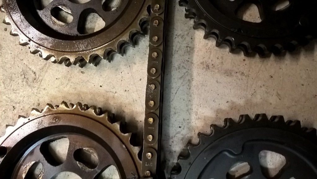
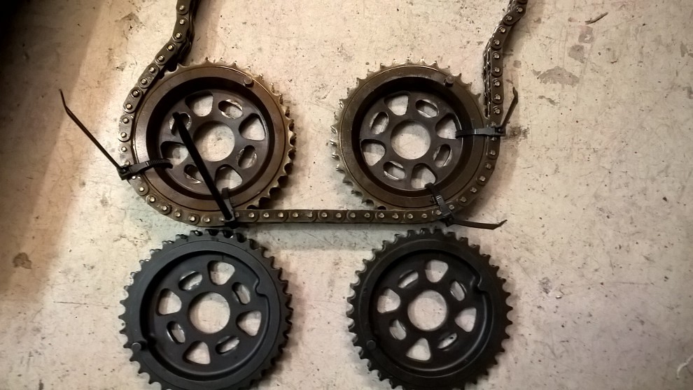
The old pointy gears with old gears showing the arrows indicating TDC. These arrows are different from the squared gears making me think that some early m42s came with these pointy gears. I read that the chain and gears should wear together so I had ordered a new chain and planned to replace it with the squared gears.
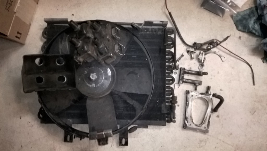
I also took a bunch of parts off the car when i had it apart. Even though I had removed the mess under the intake, I had not ever taken the throttle heater plates out. And even though I had done the COP conversion, I never got rid of the old coils and mountain brackets so I finally took those out along with the auxiliary fan and condenser.
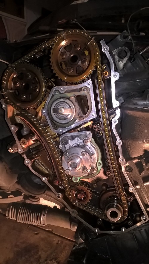
Here is a good picture of the gears/teeth and a before of the cam gear timing for my records and helping on reassembly. I counted pins on the chain to make sure I had the exact timing when I put the chain back together and as it turned out I was one link off on my first attempt. The gears look way different in color and shape.
A couple websites on cam gear timing
To shift or move the powerband up higher along the rpm range (for 1/4 mile et. improvement), you need to increase the overlap. You do this by tightening the lobe separation angle (LSA) between the intake cam's and exhaust cam's lobe centers with your aftermarket adjustable cam gears . When you tighten the LSA, you increase cam overlap duration.
Piston Timing Movement
If you want a higher powerband location, you tighten the LSA by rotating the intake and exhaust cam gears in opposite directions from one another in steady precise increments. The trick is to find the best overlap for your particular engine's package of parts and unique way of breathing compared to everyone else's.
EFFECT OF TIGHTENING THE LSA WITH ADJUSTABLE CAM GEARS
(Click for larger image)
Cam timing Dyno
FIGURE LEGEND
Hp and Torque Curves with Dots = Tighter LSA
Without Dots = Wider LSA
Wider lobe separation angle (no dots) produces more midrange torque but with a loss of upper rpm and peak torque. Narrower lobe separation angle (with dots) produces more high rpm range and peak torque but with a loss of midrange. Less LSA increases intake and exhaust valve opening overlap which creates more scavenging and a stronger upper rpm powerband. Less LSA [or more intake and exhaust cams overlap] is better for a racing engine than a high performance street engine. The idle suffers as you add more overlap since there's not enough vacuum at idle rpm.
SUMMARY OF THE EFFECTS OF TIGHTENING LSA
1. Moves Peak Torque to Higher RPM
2. Increases Maximum Torque
3. Narrows Powerband
4. Builds Higher Cylinder Pressure
5. Increase Chance of Engine Knock
6. Increase Cranking Compression and Effective Compression
7. Idle Vacuum is Reduced and Idle Quality Suffers
8. Open Valve-Overlap Increases
9. Closed Valve-Overlap Increases
10. Decreases Piston-to-Valve Clearance Obviously, widening the LSA (decreasing overlap) does the opposite to these.
Have you checked to make sure that INTAKE 0 degree and EXHAUST 0 degree markings on those cam gears were indeed set at TDC?
On a tuning session on the street or at the strip, I suggest that you do the cam gear tuning by going with a friend in the passenger seat with a stopwatch, if you don't have a datalogger that records speed and elapsed time. Do some wide open throttle acceleration runs at the 1/4 mile strip on a test & tune day. The point here is that , for each cam gear setting, do your timing over the exact same stretch of road and over the same exact distance. Have your friend time how long it takes you to go from say 30 mph to 90 mph. Do 2 runs for every setting. You want an objective measure ,like an acceleration time, to tell you if the setting is good for your particular engine. Acceration is the change in speed over the change in time. You want a higher number if the cam gear setting is good. A change of 1 tenth of a second or more consistently is good.
Don't rely on the butt dyno. It's only sensitive to changes in the early part of the rpm range.
Each person's engine will have a different optimal cam gear setting for it. Just because someone has the exact same model Integra and parts as you, does not necessarily mean that their engine and yours behave identically. Variations in performance can occur simply from minor differences in assembly at the factory, engine break-in procedures (if any) by the owner, and owner maintenance.
I would go 2 camshaft degrees at a time starting with the intake cam, since it also determines the reference baseline ignition timing as well (connected to the distributor) . Do 2 runs per setting over the same track distance. When you stop seeing an improvement in the elapsed time in between your 2 set mph points, then go back to the best setting. As for the "next best part" for your engine, I really don't think along those lines. I choose my powerband location and power goals first, and get parts that have designs or specs that will fascilitate getting those 2 goals.
An Enginebasics.com author would like to add:
While I don't have much experience with cam gear tuning on Naturally Asperated motors (N/A), I do have a lot with turbocharged motors. I have found that the EXACT OPPOSITE is true for a turbo motor as what is posted above. Adding more overlap in the lower RPM band aids in turbocharger spooling to the point that 300-400 rpm of quicker spool is easily noticed for HUGE mid-range torque gains. That overlap should be decrased substantially around peak torque, and then COMPLETLY REMOVED on the upper RPM bad to have ZERO overlap. Forced Induction motors don't like overlap on the upper RPM band since the air is being forced in, it will just be pushed in the intake and right back out the exhaust. Forced induction motors are actually hindered by the scavaging affect that can be prodeced by having cam overlap up top.
As you can see this is completly opposite to tuning an N/A motor. Also remember that the amount of overlap to have or not have will be based on the:
1. Cam Duration
2. Cam rise
3. Size of motor
Cam tuning is really something that can only be mastered on a dyno, but hopefully this article will give you a place to start depending on whether your motor is N/A, or FI.
On four stroke engines, it is important to realize that the cam rotates once for every two rotations of the crankshaft.
Volumetric efficiency is based on cylinder fill. If a 2.0L engine is filled with 2.0L of an air/fuel mixture, we say its volumetric efficiency is 100%. If a 2.0L engine fills with 3.0L of an air/fuel mixture, we say its volumetric efficiency is 150%. A forced induction engine will have a larger than 100% volumetric efficiency since the intake charge and combustion chamber are being pressurized. A naturally aspirated engine can also have a slightly larger than 100% volumetric efficiency, but it will only happen for a short duration, and is usually only in the peak of the powerband.
The art of designing camshaft profiles is meant to increase the volumetric efficiency in the RPM range that the customer requires. Camshafts don’t make magical horsepower from nowhere, they simply move the powerband around by changing the volumetric efficiency to attain the desired results.
The four strokes of the engine are:
Exhaust
Intake
Compression
Combustion
**The “start” is not important because it’s a CYCLE, meaning it repeats**
Looking at a camshaft, the sequence would be as follows: The exhaust lobe pushes open the exhaust valve and the piston comes up to push the exhaust out, then starts to close. The intake starts to open, just as the exhaust is closing, piston goes down, and the intake valve closes. Then both valves stay closed for the compression and combustion strokes. This means that the first lobe to come through the rotation will be the exhaust lobe, immediately followed by the intake lobe.
Overlap is the point where the exhaust valve is closing, and the intake valve is just opening.
To increase overlap, you have to RETARD the EXHAUST, and/or ADVANCE the INTAKE.
To reduce overlap, you have to ADVANCE the EXHAUST, and/or RETARD the INTAKE.
Simple cam tuning rules for NATURALLY ASPIRATED engines:
* Advancing both cams => more low-RPM power, less high-RPM power
* Retarding both cams => more high-RPM power, less low-RPM power
* Less overlap => more low-RPM power, less high-RPM power
* More overlap => more high-RPM power, less low-RPM power
In a naturally aspirated engine, the extra overlap is called "scavenging". Scavenging is using the out-flowing exhaust to help draw in the next intake charge (partially causing lumpy idle).
Simple cam tuning rules for BOOSTED engines:
* Advance intake and exhaust => more low-RPM power, less high-RPM power
* Retard intake and exhaust => more high-RPM power, less low-RPM power
* Less overlap => lower EGTs, faster turbo spool, less fuel
* More overlap => higher EGTs, slower turbo spool, more fuel
Boosted engines don’t like overlap. The incoming cold air and fuel cools down the outgoing exhaust charge, condensing the exhaust gasses. This is VERY counter-productive in a turbo application since the engine needs no help from scavenging to fill the cylinder. I've heard this being called "turbo chill".
Cool, condensed gasses in the same space push less hard on the turbo, causing lag. HOT gasses are better at spooling the turbo, thus the advanced exhaust timing to open the valve sooner in the power stroke. This steals some of those hot, expanding exhaust gasses to help spin the turbo a little faster. When the piston is near the bottom of the bore, hardly any energy is going into rotating the crank anyway, so stealing expanding gasses won’t hurt anything. The retarded intake just helps cut down the overlap further.
Retarding overall cam timing: Retarding overall cam timing is better for high-RPM power. This is because the valves are closing later. The intake valve is closing AFTER the piston has started to travel back up the bore for the start of compression stroke. This is terrible at low RPM because the intake air velocity is low, and air that was once in the cylinder is now being pushed back into the intake manifold and causing turbulence.
At high-RPM, the rules change. Air has weight, and thanks to Sir Issac Newton, we know that once it is moving, it doesn’t want to stop moving. This means that the air can continue to flow into and fill the cylinder, EVEN AFTER the piston has begun to travel UP the cylinder bore. This can allow an engine to exceed 100% volumetric efficiency, if even by a small amount.
Advancing overall cam timing: Advancing overall cam timing is better for low-RPM power. This is because the valves are closing a little sooner. The intake valve is closing AT or NEAR when the piston is at the bottom of the bore for the start of the compression stroke. This is great at low RPM because the intake air velocity is low and easily affected by changes in the direction of piston movement in the engine. Almost as soon as the piston gets to the bottom of the bore on the intake stroke, the valve gets slammed shut so no air can escape as the piston begins to travel back up the cylinder on the compression cycle.
At high-RPM, this may become a restriction since the air has inertia and responds a little slower to pressure changes, potentially choking the air flow to the engine a little.
Conclusion: This information is aimed at allowing tuners to understand what happens when cam timing is altered. When a larger duration camshaft is being installed, unless the lobe centerlines have been changed, the overlap will be increased. If installing larger camshafts in a turbo application, advancing the exhaust and retarding the intake will reduce the inherent increase in overlap caused by upgrading to a larger profile. Most cam grinders, especially regrinders, put the new profile in the same position as the old profile because it is easier, or the only way possible. This has to be changed when the cams are installed in an engine to attain the desired result.
A forced-induction engine should idle smooth when properly tuned, and a naturally aspirated engine should be “lumpy” and have a lope if it is tuned aggressively towards the high-RPM range. If a forced induction engine is loping at idle, fuel is being wasted, turbo spool time is being increased, and power is being lost.
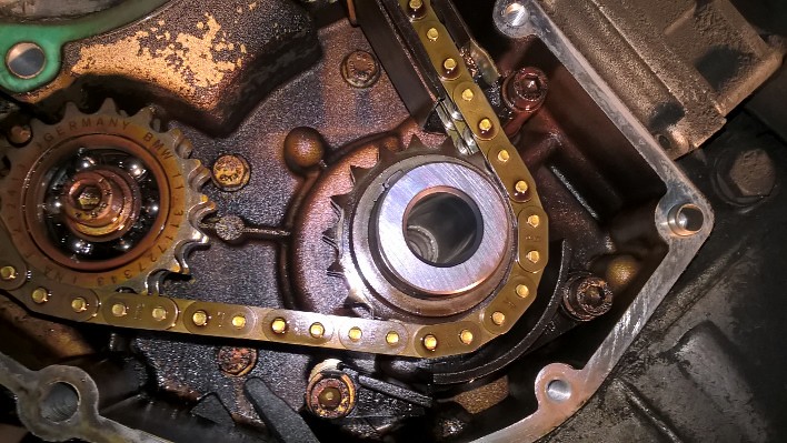
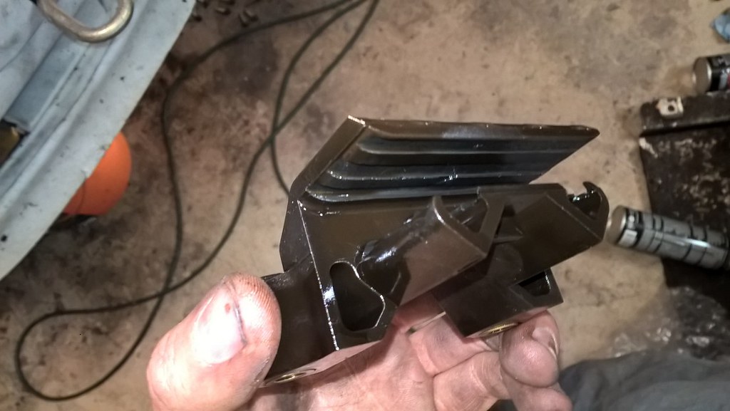
You can see the guides have been updated also. Some plastic chunks were missing from the long guide and it showed lots of age related cracks.
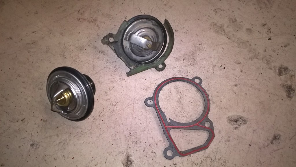
I also replaced the thermostat while I was in there since I never did when I replaced the water pump. It too was kind of seized in the motor but obviously still worked.
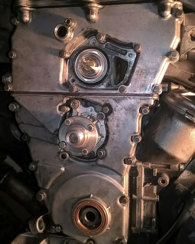
While I was at it I repainted the intake and valve cover with some high temp paint and converted to an electric fan. For the fan conversion, it is from an e36 m42/m44 and you can use the connector from the Aux fan. On mine the connector was too short so I cut the wiring off the aux fan that I removed and soldered it to my new fan to make the wiring reach the connector under the drivers headlight. Then after I replaced two fuses with 30 amps, the one blew so I uprated the fuses to 40 amps. With this configuration the fan either turns on based on coolant temperature switch, or if the AC button is pressed as a manual over ride. I need to replace the coolant sensor with part number 61318361787 to turn the aux fan on at 80 C instead of 90 C. After reassebly, I reclocked the cam gears to approximately what I have in the photo above and got the engine to fire back up. It idles nice at 900 rpm and seems to have gone without a problem.
If you have a keen eye, you will see the turbo in the first photo of this post. I had it sitting connected directly to the turbo manifold, but after testing that is not going to work for this car based on the wastegate actuator arm, clearance for air inlet, and the exhaust flange.
I am planning on a custom manifold that will set a t25 flange at the passenger headlight area which will make everything easier including the oil feed and drain. Next up is a turbo manifold.318iS Track Rat :nice: www.drive4corners.com
'86 325iX 3.1 Stroker Turbo '86 S38B36 325
No one makes this car anymore. The government won't allow them, normal people won't buy them. So it's up to us: the freaks, the weirdos, the informed. To buy them, to appreciate them, and most importantly, to drive them.Comment
-
Looks like a lot of work, nice job! The car is always improving it seems.
I always enjoy the updates...Comment
-
This is more of a record than anything for the car.
Since the last update I have gotten the car running on megasquit and driving around but driveability wasn't smooth enough and I decided to run it back N/A. But I had taken the exhaust off to prep for turbo after it failed. To do that I needed a catalytic converter and stock exhaust header and down pipe. I found a magnaflow cat and got a stock manifold from ebay for cheap and bolted it back together. I had to modify it but was able to use some exhaust clamps and the exhaust that it came with. I ordered a replacement muffler to see if i could clean it up a bit and it looked decent for a minute. Also the gurney flap and cliq tuning spoiler showed up and I installed it. Unfortunately the gurney flap fell off and I have to figure out the screws to reattach.
Then in early November I was able to get back to the track for the first time in quite a while. It was great to get out there. A number of upgrades since the last time at the track.
- COP Conversion
- e36 electric fan conversion instead of fan clutch
- stock exhaust manifold instead of aftermarket ebay header
- sssquid tuning chip vs ebay chip
- wideband oxygen sensor
- modified/clearanced firewall where z3 steering rack was rubbing
- cliqtuning spoiler
- passenger mirror delete
- m20 clutch, pressure plate and 11 lb m20 lightened flywheel
- new shifter bushings
- intercooler plumbed to nothing from failed turbo attempt
- got one fog light replaced and working, the other wiring seems to be messed up
With these upgrades I dropped my lap times significantly with the same wheels/tires from 2:24 to 2:16s without a passenger. In the slow group I was able to pass most every car on track with my slicks including an e39 M5 and it was fun.
Here are a couple of videos from the track, in car and following from the lapping day.
A 325i chasing me in my fastest session of the day (only without a passenger)
A little hard to see but being chased by a 635csi
And I have hit 21k miles driving this thing. It is just so much fun to rev it out with the 3.73 and the lightweight nature.
After the lapping day, I thought it would reduce my desire to drive this car fast, but I think it did the opposite. Afterwards, I picked up a Z3 short shifter and was looking for some 15x7 wheels. I got around to installing the Z3 shifter the other night which is a nice upgrade. While I was at it a local had a damaged carbon fiber hood that I was able to snatch as well. I got that installed the other night. The hood hing threads were the wrong size so I had to pick up some M8 bolts from the hardware store and got them installed and the hood bolted down on the car. I have mixed feelings about the look but the hood is the nicest thing on here now and has minimal damage all in all.
Going to pick up the hood, I took the stock hood off and noticed some coolant. The upper radiator hose had a hole in it so I got home and replaced that last night. Another thing I noticed after the track day was the passenger rear axle boot is torn and the diff or the driver rear wheel bearing seems to be making noise. I drained the diff of the gear oi I had in it and put in redline 75W140 for track use and ordered new rear axles and rear wheel bearings. I hope to swap those out soon. Here are a few picture of the hood, there is some dust on it from sitting outside overnight.
318iS Track Rat :nice: www.drive4corners.com
'86 325iX 3.1 Stroker Turbo '86 S38B36 325
No one makes this car anymore. The government won't allow them, normal people won't buy them. So it's up to us: the freaks, the weirdos, the informed. To buy them, to appreciate them, and most importantly, to drive them.Comment
-
So the whole turbo setup failed? Any idea what would have made it all work? Megasquirt issues from adapting a PNP for it?
I'm still going back and forth on whether I want to turbo mine. Wish I wouldn't have sold off the manifold and turbo to you a while back.Comment


Comment