Announcement

Collapse
No announcement yet.

E30 M42 to Motronic 1.7.3 Conversion Project

Collapse
X
 
  • Filter
  • Time
  • Show
Clear All
new posts

    Originally posted by bmwman91 View Post
    Do you think that all of the necessary switches (disabling DISA, EWS, etc) can be done through the XDF with small or no firmware changes?
    Unfortunately, you not see my XDF at all, because you can run your engine on M1.7.3 just NOW. All switches and disabling done for a long time ago.
    Switch CTS to IAT curve (for old CTS NTC sensors), disable EWS, disable DISA, disable knock control subsystem...
    I will check if added to custom firmware change injector size or not, because think I'm forgot about this.
    Also need upload new XDF with lambda heating relay settings (can switch it to work constantly without relay soldering).
    I'm investigate where performed consumption signal and of course need custom code for modify it, this is not surprising because any BMW M1 Motronic havent FGAT constant for adjust injector size, so its means that consumption signal is cant adjust too (of course for stock) :)

    Comment


      Are the switches in the XDF more of setting "impossible" limits/thresholds for things like DISA, rather than on/off 1/0? I am not as familiar with some of the terminology in there and the RAM definition list...much of it I can guess, but some is written more for people with experience in these systems (aka you!).


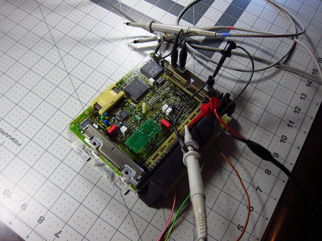
      I did a little hardware work tonight since for many of the still unknown things in the XDF and ROM we will need to test the effects. So I started working on an "M42 Emulator" setup to be able to bench test the ECU more thoroughly. M1.7.3 will need EWS disabled to work, so I will look through the XDF again for that. Just to test that it is feasible, I hooked up my arbitrary waveform generator to a spare M1.7 to make a very basic crank sensor signal with a 60-2 pattern at 900RPM. It worked fine, and the ECU was operating the ignition and injector outputs. I will look into simulating the other sensor signals now, probably just some fixed values to start out. This could help with testing things like injection constants since all inputs can be made repeatable and we can look at injection pulse length changes. The JimStim product might be exactly what I need to simulate everything since it is a readily available product designed to almost everything we need here. Then we can look at the actual outputs, and it will also be easier to use my logic analyzer (or an Ostrich?) to do ROM tracing for direct monitoring of ROM and RAM accesses.

      The setup:


      I manually programmed a very simple 120 point waveform into the generator which makes 58 hi-lo pulses and 0v for the last 2 periods (yellow). This seemed to be more than enough to satisfy the level detection circuitry in S600, so it was making nice TTL pulses for S700 (pink).


      With the ECU in limp mode, it was making injection pulses (green) in an interesting pattern. There were 4 ~7.2ms injection events (one per crank revolution), and then a ~51ms event and a ~18ms event meaning that injection is being requested for almost an entire crank revolution. I was not watching the LL/KS lines (controlled by S700.32), so maybe the driver was disabled at this time or something, or maybe it is just part of the limp mode coding to run very very rich. Since there was no cam sensor signal, both pairs of injectors were being fired at the same time.


      More to come.....
      Last edited by bmwman91; 04-04-2018, 12:24 AM.

      Transaction Feedback: LINK

      Comment


        Are the switches in the XDF more of setting "impossible" limits/thresholds for things like DISA, rather than on/off 1/0? I am not as familiar with some of the terminology in there and the RAM definition list...much of it I can guess, but some is written more for people with experience in these systems (aka you!).
        Some used as switch, some used as impossible limits - depends on functional. For example CTS switch for NTC, is just replace one table index to another (FROM CTS TO IAT) :) EWS switch is just skip routines and set flags for allow injection and ignithion. For DISA you can just remove DTC code ad so on, because is just switch for equipment, not for functional. Ask what you want to do when you migrate to M1.7.3 and I'm answer what you need to switch or disable.

        Comment


          For disable EWS you need compile CLEAN firmware form dropbox and flash to your EEPROM. There is no way to disable EWS in stock for M1.7.3.

          Comment


            I am doing a text compare of your ORIGINAL and CLEAN asm files and will try to understand what was removed or changed, and why.
            EDIT: Went through the comparison. It looks like the small changes at 0cC988 are the ones to bypass EWS. I do not see many other (only one) references to RAM 0xBB...are the places it is written to areas where R0 gets incremented from some lower value first? The added code to force XRAM 0x270 & 0x271 seems to depend on 0xBB.1. Anyway, is it the case that whatever check is done with S702 to verify EWS is still there and failing, but these small changes are all that is needed to make the rest of the code ignore it?

            If all M1.7.3 have the same ROM code, then is it correct that EWS-II on these cars is not unique to the ECU itself and whatever "handshake" gets done is the same on all of them? So basically, the EWS module is coded to the RFID in the key only? I am wondering if it is just a 12V/0V sequence during engine start/run and the ECU just wants to see the correct levels at the correct time. Anyway, I guess that you removed all of the stuff that relates to this so maybe the specific function is not so important, but I like to know random things! Getting a little more understanding of this might also help with understanding communication with S702.

            I am going to order the JimStim board so that I can run M1.7.3 on the bench at home. It will be a while before I commit to switching it into my car because there is a lot that I want to know/understand before I have to depend on it to go places. Switching around the wire harness is not something that I want to do more than one or two times, and I do need this car to get around!
            EDIT: JimStim order placed, should have it soon.
            Last edited by bmwman91; 04-04-2018, 10:09 PM.

            Transaction Feedback: LINK

            Comment


              Originally posted by bmwman91 View Post
              Went through the comparison. It looks like the small changes at 0cC988 are the ones to bypass EWS. I do not see many other (only one) references to RAM 0xBB...are the places it is written to areas where R0 gets incremented from some lower value first? The added code to force XRAM 0x270 & 0x271 seems to depend on 0xBB.1. Anyway, is it the case that whatever check is done with S702 to verify EWS is still there and failing, but these small changes are all that is needed to make the rest of the code ignore it?
              I'm just add code to skip EWS check, thats all.

              Originally posted by bmwman91 View Post
              If all M1.7.3 have the same ROM code, then is it correct that EWS-II on these cars is not unique to the ECU itself and whatever "handshake" gets done is the same on all of them? So basically, the EWS module is coded to the RFID in the key only? I am wondering if it is just a 12V/0V sequence during engine start/run and the ECU just wants to see the correct levels at the correct time. Anyway, I guess that you removed all of the stuff that relates to this so maybe the specific function is not so important, but I like to know random things! Getting a little more understanding of this might also help with understanding communication with S702.
              From S702 EWS given only strobe pin. From this pin and 10 ms timer implemented some one-directional one-wire protocol, exchanged information between EWS and DME. More details are described in the EWS documentation - "Understanding BMW EWS", just skip all about EWS 1 and read about EWS 2.

              Comment


                This post is probably not all that useful, but I like to see how stuff works so here goes...


                The communication from the EWS-II module should be pretty simple. One-directional asynchronous timing (or maybe the transmission starts at the time of a start request). I have seen the "Understanding EWS" document. Pin 39 on S702 which the EWS signal connects to is an input-only pin based on the images I took, and it looks like it is bit-0 of a read from 0xA040 since the line coming out of that pin (on the silicon chip) connects into D0 through some switching logic. I spent like 8 hours today messing around in IDA tracing through the EWS/ISN calculation and verification.

                The ISN looks to be stored as 4 ASCII digits in ROM 0xFFD1:FFD4. Since I have 3 eBay M1.7.3 units, this was easy to figure out by comparing the EPROM dumps...all were different values at that location. Some other little stuff above 0xFF00 also varied, but those 4 locations are the part that matters for EWS (the "full" code is 9 digits looking like 0000xxxxx, but only the last 4 xxxx get used as far as I can tell). The code in RESET at 0x673F is where the look-up and calculation happens. Basically, the 4 ASCII digits get converted to a hex value and truncated to 3 bytes. For example, in the BIN you (Rasp) put in Dropbox the ASCII values from ROM are "7627" which is 0x1DCB. Based on some info I saw on ecuconnections for M1.7.3, the EWS module only sends a 3 byte code, which would be 0xDCB. This matches what the code at 0x673F does...takes the ASCII formatted values, converts to hex and stores only the 3 LSB's in XRAM 0x272:273.

                That much is the super easy part. Where I spent all of my time was in figuring out where XRAM 0x272 & 273 get tested against the value that is read from S702. It is pretty clear that the values in those locations need to match something else in order to branch to the code where XRAM 0x270:271 are set to the values 0x97:BA. There look to be 2 places in all of the code where 0x270:271 are tested to match those values, and I can see that your "clean" ASM essentially forces those values.
                - Code 0xC988 is one place that checks, and you added some code to set XRAM 0x270:271, IF RAM 0xBB.1 = 1. I am confused by the RAM 0xBB test since I can't see anywhere else it is referenced...does simply setting 0x270:271 to 0x97:BA every time lead to problems?
                - Code 0xC6B1 is the other place that tests these RAM values, and it also appears to be the main place where the ISN verification is done.

                Bosch certainly did not make it easy to tell what the heck is going on in both obtaining the ISN code, and in doing the verification calculations. It all seems needlessly complicated, maybe to make it difficult for people to hack. From what I can see, the relevant information for the verification is stored in XRAM 0x274-280, with some of it being input from S702, some looking like counters and some storing low-bytes of pointers to other needed variables. As far as the input from S702 goes, it looks like that is done in the TF1 ISR at code 0x26C3. I assume that is the case since this looks like the only read from 0xA040 which is tied to a timer, and various conditions are tested which affect XRAM 0x27E:280.

                Anyway, it is probably not all that important to really understand this since it looks like the CLEAN ASM bypasses the EWS check. I cannot compile the ASM yet because mcu8051ide seems to be mostly designed for Linux and trying to compile it for Windows seems to require a lot of dependencies to be installed. If there are any other decent free 8051 compilers out there, which are Windows compatible, let me know. In the mean time can you compile the CLEAN ASM file into a BIN so that I can test it out?


                In other news, the JimStim kit arrived today and I am looking forward to getting the ECU running on a simulated engine!

                Transaction Feedback: LINK

                Comment


                  True ISN is a last 3 symbols from hex value of 0xFFD1-FFD4. So for "7627 which is 0x1DCB" is DCB. All other EWS stuff is useful only for detect that is EWS part in code and skip it reversing :) And mark variables in RAM as EWS-used and leave it alone.
                  0xBA and 0xBB is related to engine configuration which you can see on DME lable (801C),
                  I'm make EWS disable solution compatible with M1.7.2 configuration definition, so you can use EWS or disable it for one bit.

                  I cannot compile the ASM yet because mcu8051ide seems to be mostly designed for Linux and trying to compile it for Windows seems to require a lot of dependencies to be installed.
                  I'm give link to compiler 100% compatable with my produced ASM in my first post :) Try to re-read all this stuff, I think after this question will be less.

                  Comment


                    You dont really need to recompile the whole program to make small changes like an EWS delete. You can often just edit the instructions right in IDA, copy the hex changes to your binary (usually just a couple bytes) and correct checksums.
                    Last edited by nando; 04-17-2018, 09:37 PM.
                    Build thread

                    Bimmerlabs

                    Comment


                      Small update. I assembled the JimStim today and have ordered the required serial-to-TTL cable so that I can properly program the cam pulse timing relative to the 60-2 crank signal. I should be able to emulate all of the inputs/outputs which are needed to simulate a normal running M42. The only sources of error codes should be the ignition outputs since there will be no 450V flyback spike to trigger the monitoring circuitry (if less than ~100V spike appears on the coil switching lines after firing, the 80C515 can detect this and show a fault for that coil). The O2 sensor signal will lead to an error code too since it is just a DC voltage, so I might just leave it unconnected so that the code will just give an error and ignore its effects.

                      With this I will be able to directly measure the various outputs of the ECU, with the main interest being the injector pulsewidth. We will be able to manually adjust some of the fueling constants and verify the effects if there are any cases where we need to test things to make sure of them.

                      Transaction Feedback: LINK

                      Comment


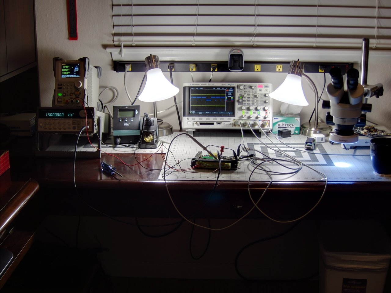
                        Random question....you must be left handed, no? (workbench layout gave it away)
                        Originally posted by Matt-B
                        hey does anyone know anyone who gets upset and makes electronics?

                        Comment


                          That's a rad scope. Mine is Apple2e-esque, complete with monochrome.
                          john@m20guru.com
                          Links:
                          Transaction feedback: Here, here and here. Thanks :D

                          Comment


                            Originally posted by george graves View Post
                            Random question....you must be left handed, no? (workbench layout gave it away)
                            lol, yes you got me.

                            Originally posted by ForcedFirebird View Post
                            That's a rad scope. Mine is Apple2e-esque, complete with monochrome.
                            Yes, it is a pretty handy scope!

                            Transaction Feedback: LINK

                            Comment


                              (keep in mind, the below applies to M1.7 only, I have not checked this on M1.7.3 yet)

                              It's been a while since any updates. Things have been busy and there are a couple of non-car projects demanding my attention. But, I did finally have a chance to get the JimStim hooked up and it seems to operate the Motronic reasonably well. I can get the Motronic to run in coil-per-cylinder ignition and semi-sequential ignition mode, so obviously much of the input is correct.

                              The CEL indicator is on, and there are two obvious reasons: the cam pulse is 120° early and the ignition fault detection circuit is going to indicate faults on all coils since there is no ~350V flyback to from a coil to trigger it. The CEL code (yes, I can fake the "stomp test") is 1252 indicating "Fuel injector bank 2" is at fault, and I have no idea what that means. Really, I am not sure which errors actually affect operation and which do not. Clearly whatever the case is, the thing seems to function pretty completely.

                              As of now, the test setup is using a spare M1.7 since I am still running the car on that, and I want to get the tune finished on that before swapping ECUs. With the JimStim setup I am hoping to work out a few final factors that seem related to the injection constants, as well as trying to get a better understanding of the O2 feedback operation for a possible wide-band conversion (the M2.3.2 community had a guy make this modification).

                              Earlier I was playing around and measuring the injector pulsewidth. As expected, changing the AFM, IAT and RPM inputs had the most significant effects on this. Playing with coolant temperature also changed the width, as well as switching into batched (all injectors at once) firing mode below a certain temperature threshold. There are actually a variety of "impossible" conditions that I can create with the potentiometers which cause the Motronic to go into different operating modes, but I am not really trying to do any of that.


                              One other interesting thing that I found is about how the ignition system actually functions. S702 is not actually controlling the dwell timing or length at all. It is only used to select which coil to fire (it controls the 4 selection lines going to S500). Here's the signal chain which actually sets the dwell timing and duration:
                              - The dwell is ultimately started and stopped/fired by the signal coming from pin 31 of S700 (P1.5 / T2EX).
                              - This signal from S700 pin 31 goes to R731
                              - From R731 it can either be:
                              - a) Bypassed by T730 during a reset or power fault, or
                              - b) During normal operation it goes to pin 18 of S600 ("TS").
                              - The signal input to S600 pin 18 is output and inverted on S600 pin 16 ("ZDG")
                              - The signal from S600 pin 16 goes to S500 pin 1 ("NRS"), and this is what actually enables the base current driver outputs

                              This isn't super important or anything, but it is interesting, and I need to make some updates to the schematic with better names for a bunch of signals.

                              Transaction Feedback: LINK

                              Comment


                                Other interesting developments...

                                It turns out that those 6-channel medium current transistor arrays (S400/450/470) are a bit "smarter" than I initially thought. They are not just current switches, and in fact they provide feedback to the MCU. The 6 input (E) lines are bi-directional, and provide feedback to the driving circuit (S700 & S702) about whether or not the output is actually functioning. I have not yet figured out whether the feedback is based on a certain current being sunk, or if it just wants to see a certain pull-up voltage present (since the device being switched is connected to constant 12V. The MCU IO lines connected to the array inputs are bidirectional, with weak output drivers, they can be used to send a control signal and then be pulled high/low by the slave device and read by the MCU to determine the feedback status.

                                So this is starting to answer my questions about why there are fault codes for all of the relays, the idle control valve, evap purge valve, etc. There is no separate circuitry for the MCU to use to detect a fault in those things, and at first I thought that maybe there was some clever software trick for figuring it out based on engine running behavior, but now I can see that there is direct feedback from the driver arrays.

                                The feedback for the fuel injectors is a little different. For the drivers connected to all of the non-injector stuff, it seems like sinking 10mA (maybe less, I have not done extensive testing to find the limit yet) is enough to enable the feedback signal. For the injectors, I tried a bunch of different resistors, and it seems like there is feedback only when the output is connected to a resistance of 20 Ohm or less. It is the same part number as the other arrays, so somehow the current threshold is being programmed. The other difference is that the LL + KS lines are connected to an IO on S700 for the injector driver, and those lines are pulled-up to 5V through a resistor on the other driver arrays. A little probing with the oscilloscope shows that the LL + KS lines on the injector driver array will make short pulses when they are sinking current through a load of 20 Ohms or less, but I do not really know exactly if it is the driver or MCU that is generating this or why.

                                Lastly, since I now know that I need to have certain loads present to make the Motronic think that it is actually connected to a real engine, I am building a separate load board to fake the various loads it needs to drive. The JimStim board is fine for making the needed input signals, but it cannot provide the output loading that is needed.

                                Well, that is a enough text for now. I will try to get some scope shots up here for the stuff I have been mentioning in the last couple of posts.

                                Transaction Feedback: LINK

                                Comment

                                Working...
                                X