
I would agree, keep me posted on the 200 ohm setting
-

Closing SOON!"LAST CHANCE FOR G.A.S." DEAL IS ON NOW
Luke AT germanaudiospecialties DOT com or text 425-761-6450, or for quickest answers, call me at the shop 360-669-0398
Thanks for 10 years of fun! -
Things are good with the 200 Ohm setting. No alternator whine or other undesired noise, and bass seems to be much improved. I still need to turn the sub gain up a bit more than I did when I was using the 6XS "Ground" jumper setting, but it is nowhere near maxed-out like it was with the "Isolated" jumper setting.
I also got my DMM in there to see what sort of current is moving through the RCA cables (and thus through the 24ga ground wire that ties my pre-amp board into the RMT-200). I measured 0.2mA DC and 6.1mA AC current with the car running, which is totally acceptable from a safety standpoint. When I had the grounds linked (and the noise was a big problem) I was reading more like 100mA!
I probed around inside the 6XS a little too. Basically, here is how the 3 jumper settings work:
Ground: The RCA in/out grounds are tied directly to the 6XS ground terminal (on the block with 12V and ANT).
200 Ohm: There is a 200 Ohm resistor between the 6XS ground terminal and the signal grounds (inputs AND outputs)
Isolated: Not sure, honestly. There is no continuity between the two grounds, and both of them connect to the transformer that lies behind the jumper. The signal lines do not seem to touch the transformer, so this is a bit different than an aftermarket isolator, but the bass reduction remains the same. Since the 200 Ohm setting seems to work, I am not going to worry too much about how the Isolated setting couples the grounds (and it is weird because it looks like both ends of the winding sets are tied together on each of the 2 ground circuits).
So as it is now, it looks like the RMT-200's signal grounds (RCA shields) are linked to the 6XS ground through a 200 Ohm resistor, making the amplifier's RCA grounds the other endpoint. It seems like most advice about alternator whine on the web says that the head unit and amplifier need to use the same signal ground, which is now the case.Comment
-
Good to hear!
Closing SOON!"LAST CHANCE FOR G.A.S." DEAL IS ON NOW
Luke AT germanaudiospecialties DOT com or text 425-761-6450, or for quickest answers, call me at the shop 360-669-0398
Thanks for 10 years of fun!Comment
-
Puns FTW. It does sound good. The bass is a little sloppy though, but I think that's more of a function of the "infinite baffle" setup I have going with my sub. I still have to install my 8" Lukebox and Alpine SWR-8D4 sub, which I am thinking might provide an improvement since the ported box is well designed and tuned, versus the 11" sub in there now which is basically just stuffed up against the bulkhead.
What do you think...11" low-profile sub driver in IB, versus 8" driver in a ported box?Comment
-
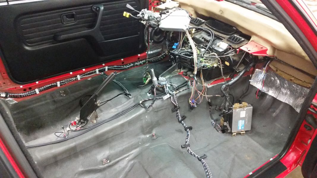
Also, I re-did all of the speaker and signal wiring. The speaker wires I had in there before were 12ga zip-cord. Those are out, and I made my own twisted-pair conductors from Belden 18ga wire (the black and white wires you see).
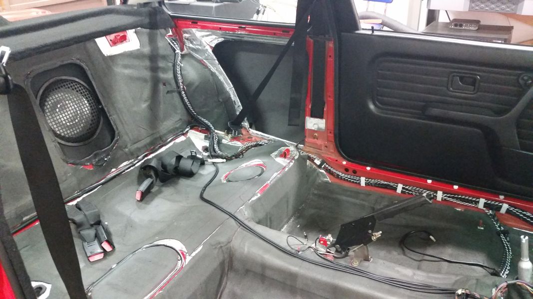
The RCA cables were also custom-made since just about every off-the-shelf cable I have seen is total crap in terms of shielding (either inadequate, or non-existent). So, I ordered up some Canare shielded 2-conductor microphone cable and Canare plugs (3.5mm TRS for connecting to the RMT-200, RCA for the 6XS). I trimmed everything to the perfect length and installed it. The Canare cable is burly as hell, and the braided copper shielding has 95%+ optical coverage (which is a very good thing). The plugs are also stout and have beefy strain reliefs. You can see the pre-amp signal cables running down the top of the tranny tunnel and under the rear seat. Since that is an area that can be stepped on and sat on, that is why I went with the Canare mic cable since it is designed for use on stages where rockers on 5-day coke binges are stomping around.
I also trimmed the RCA cables between the 6XS and amplifier to be the perfect length so that there is no slack or slop to deal with back there (I'll try to get a couple of pics tomorrow). Man, this RMT-200 mods thread is starting to turn into my audio-overhaul 2.0 thread!
Here's the Canare mic cable that I used:

The Canare 3.5mm plugs:
The Canare RCA plugs:
The Belden 18ga wire was acquired at a local surplus electronics store. It's legit stuff, rated for 300V and 105 Celsius operation. While that may seem "thin", it is plenty heavy enough for the mids and tweeters that is connects to the Amplifier. The subwoofer still uses 12ga zip cord since it is about 14" away from the amplifier in the trunk.Last edited by bmwman91; 08-14-2015, 12:01 AM.Comment
-
Shameless plug for parts I have for sale...
Anyone here want to pick up my CD43, LC6i line level converter, a GROM Aux input and customized HVAC panel that works with the CD43?Comment
-
Wonder if this is similar to the RTM200 -

But on another topic
I have a VDO/Continental with ISO inputs, how did you get your power antenna working?
It looks very similiar to your clarion unit but without the CD function.

Comment
-
The RMT200 has a 5v amp turn on output, you can use a micro relay to make it run the antenna
Closing SOON!"LAST CHANCE FOR G.A.S." DEAL IS ON NOW
Luke AT germanaudiospecialties DOT com or text 425-761-6450, or for quickest answers, call me at the shop 360-669-0398
Thanks for 10 years of fun!Comment
-
In my radio, there was all of the circuitry for the switched 12V output and even a dedicated pin for it. There was just one little component missing which would connect the internally switched 12V signal to that pin, so I bought one of those components and installed it. Bam, working 12V output.
As Luke mentioned, there might be a switched 5V output or something like that. You can buy small signal relays that can be activated with a 5V signal, and then use that to switch a live 12V signal from elsewhere in the wire harness.
Brickwhite, if you are willing to open up your unit and take some good macro pictures of the PCB, I might be able to tell you if there is anything available to enable a switched 12V output.Comment
-
Time for more pics and info. Since some folks that are interested in buying my boards want to do the installation themselves, this post will serve as the how-to for soldering things into the correct places and other installation-related topics.
First off, none of the soldering involved is terribly challenging for anyone with prior soldering experience. The smallest component involved is an 0805 chip ferrite, and there are some 24ga wires as well (which are probably the bigger challenge). However, a couple of the places you will be soldering to are connected to big ground planes, which require a lot more heat than signal pads, and of course this thing is made with lead-free solder which is the bane of everyone that owns a soldering iron.
Do not let this be your first soldering experience. If you have not soldered before, either find someone that has, or practice with scraps first. You can get little prototyping boards very cheaply at local electronics stores like Radio Shack. Buy one of those, and some 24ga stranded wire, and maybe some other miscellaneous components. Practice soldering them to the proto board first to get a feel for how the solder flows and fills. Also watch an hour's worth of Youtube videos on how to solder surface mount components. "Winging it" is not worth messing up your expensive radio, so study up and practice.
Here are the tools and materials that you will need:
1) 15W soldering iron, 25W is better
2) (optional) A second soldering iron, 15W or 25W. Removing one of the surface mounted electrolytic caps will make installing the 24ga signal wires a LOT easier, and using 2 irons greatly reduces your chances of ripping pads off of the board (and repairing that sort of thing suuuuucks). Dual wielding brah!
3) Precision tweezers
4) Rosin-core solder (I like Kester SN63PB37 #66/285), 0.031" diameter. Just about anything will be fine though.
5) Liquid flux or flux paste (no-clean type preferred)
6) Digital multimeter for checking continuity (beep beep)
Start by removing the main board from the RMT-200. See my first post for info on this.
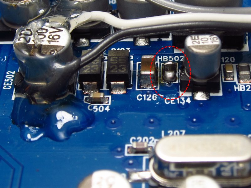
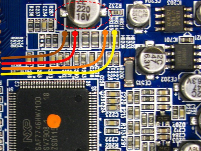
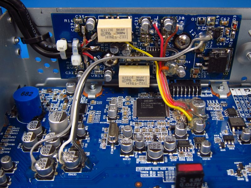
If you are installing the chip ferrite to enable switched 12V output, install the ferrite in the location shown (circled in red, already installed). Try not to hit the big capacitor with the iron since that kind of heat is bad for it. Yes, the power wires are already installed in this image...BUT, install the ferrite first because those power wires will be in the way otherwise!
Proceed by connecting the power lines. Here's where each of the 3 wires goes. For these 3 (and the next 4), heat up the existing pad to melt the existing solder, and then add a little bit more of your own solder. Apply some flux to the exposed metal of the wires, re-melt the new solder blob you made and stick the flux'ed wire in. Note that wires' the insulation will probably melt a bit near the end where you are soldering.
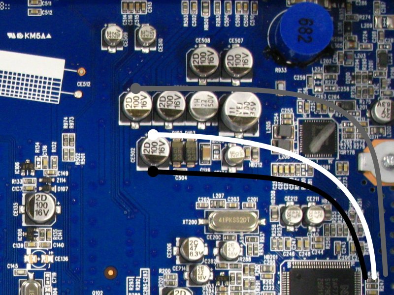
Here are the wires installed. Note that I encased them in hot glue. This is probably unnecessary, but I really don't like to have solder joints carrying fatigue stress from vibration. If you want to do the glue step, don't do it until after you are completely done and have tested this thing out. Pulling the glue off could damage components it is stuck to, so consider it permanent if you use it.
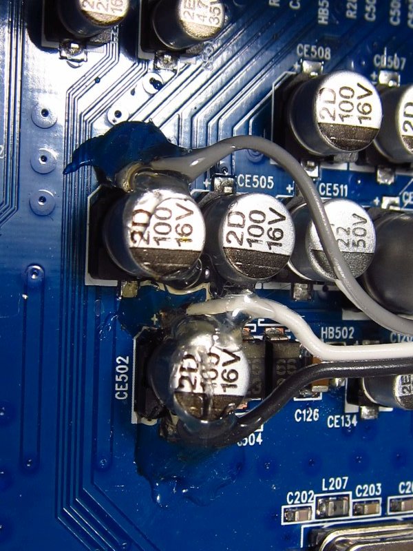
Next, connect the 4 signal lines. I highly recommend removing the capacitor that is circled toward the top of this image. Doing so makes it a LOT easier to get the signal lines in place. This is also why I recommend having 2 irons. Also, when you put the cap back in place, make sure it is oriented the same way because this one is polarized (has + and - terminals). Nag nag nag...don't forget to put that cap back!
Again, here's the finished product. Same story with the glue.
After this, use your multimeter to make sure that none of the signal lines are shorted to each other, adjacent components, or ground. Also make sure that the white and gray wires are not shorted to ground (the black wire).
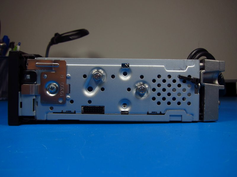
Now it is time to mount the board into the chassis. This should be very self explanatory.
Don't forget the nylon washers between the PCB and chassis.
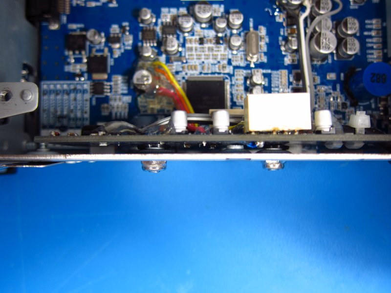
When tightening the nylock nuts, do not go too crazy. You don't want them so tight that they mash up the washers between the PCB and chassis. Tighten them enough so that you can be sure that the PCB cannot move around, but don't go nuts (bad pun).
OK, your pre-amp board is now in place. Before reassembling things (you don't need to put the CD transport back in yet, but when you do, make sure that it isn't mashing any of the wires you soldered), connect the radio to the harness in the car and make sure that the 3.5mm TRS outputs are working and sound good. You can connect headphones to the 3.5mm connectors to test this. Also, you should hear the relays click ON about 2 seconds after the radio powers on, and they should click OFF at the same instant as the radio turns off (either with the power button or by turning the ignition key off). There should be no audible pops or thumps at power on or power off except in one case: when power is lost because you unplugged the radio while it was on (or disconnected the battery). For that last case...obviously don't do that, for lots of reasons.
The final step is to cut the sheetmetal top cover a little bit so that the two 3.5mm connectors' wires will fit through. You can do this with a Dremel or tin snips. Just make sure to file the sharp edges off (far away from the radio so you don't get metal shavings in there!). Once you have a nice clean cutout, zip tie the output wires into place as shown in the image above, reassemble the unit. Good to go!
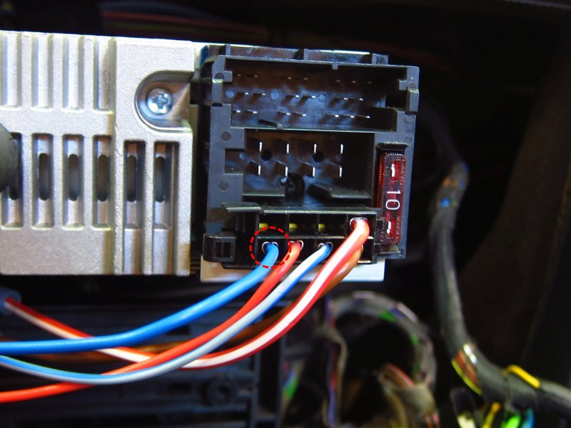
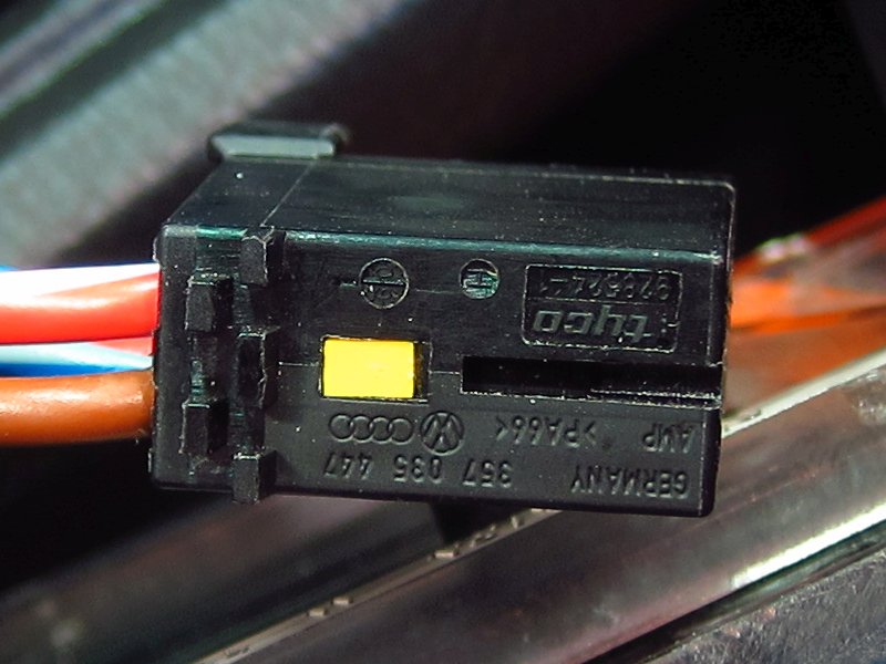
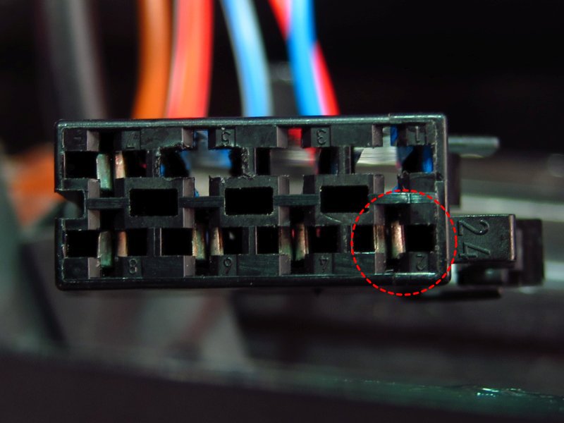
If you also bought the switched 12V pigtail, here's the deal with installing it into the rear connector. To insert the terminal, just pop the little yellow lock strip out with a tiny flat blade screwdriver. Put the terminal into position #2, facing the same way as the other terminals on the bottom row. Once it is seated, put the yellow lock strip back in. Now you have 12V switched output for remote turn-on (this will only work if you installed the chip ferrite in the first step).
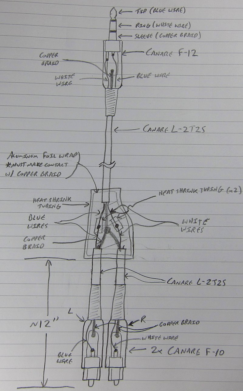
And finally, for those that want to build their own high quality RCA cables, I made a quick little hand drawing showing what I did when I built mine. These work great, and I sleep well knowing that the shielding is excellent. I bought a number of retail RCA cables of varying prices and brands to chop up and inspect, and they were basically all garbage with lousy shielding. The cable that I am using is stage-grade microphone cable, so not only can it take a real beating, but it has an actual spec sheet and guarantees that the shield has at least 95% optical coverage in the braid (and braid is much better than spiral wrap). In a car environment where ignition noise and EMI are huge issues, you can't afford to use cables with shitty shields around a single-ended signal like this.
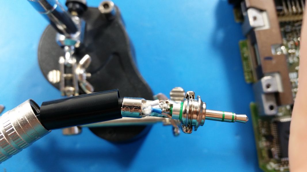
Also, yes, I am running left and right signals through a single cable. No, this is not a problem and you will not have cross-talk issues. There is nowhere near enough current, or high enough frequencies, involved in this application to make crosstalk a concern. All connections in this are done with solder. See my post slightly above this one (#95 in this thread) for an example of one of the plugs, as well as links to the plugs and cable that I used. The total cost of the 2 3.5mm plugs, 4 RCA plugs and ~40ft of mic cable was less than one 12' Monster RCA cable, and the quality is vastly better. These will also be the perfect length for your car since you can measure and cut them to fit exactly right.
Once you have soldered the wires to the plugs, use your multimeter to make sure that none of the wires are shorted to ground or each other (the wires have very fine stranding and one could be sticking out as a "whisker"). Also make sure that the segments of the 3.5mm plug have continuity to the proper parts of the RCA plugs.
 Last edited by bmwman91; 11-17-2015, 11:38 PM.
Comment
-
Very nice! One of these boards is on my To-Do list after the holidays....-Geno
'87 325is (s52'd)
'95 525iT
'02 Range Rover 4.6 HSE
'98 Disco 1Comment
-
Awesome. You think you'll DIY the installation? It's pretty straightforward.Comment
-
Yeah, I'll most likely DIY it. I've got soldering experience, just nothing this small, so I may buy some practice kits. Swapping to the Amber LEDs would be a nice touch too if I can make that happen.-Geno
'87 325is (s52'd)
'95 525iT
'02 Range Rover 4.6 HSE
'98 Disco 1Comment
-
Hello,
i just got my rmt200 in the mail from Italy for my 1996 vw passat. For some reason it will not turn on, I'm 99% sure I have the wiring correct. What troubleshooting can I do? Would someone on here be able to take a look at it for me if I ship it? I live in CO, may e a local can help me troubleshoot?Comment
-
Hey, sorry I didn't reply to your PM yet, I have been busy getting the engine reassembled and back into my car (and enjoying some California sun).
Post up the pinout that you used for all of your connections. Do you have the version of the RMT200 that is branded as Clarion, or the one that seems to be a "Genuine VW" unit that has the pinout diagrams and stuff on the label on top?Comment


Comment