Announcement

Collapse
No announcement yet.

CM5908/5907 Plug-n-Play Bluetooth upgrade board

Collapse
X
 
  • Filter
  • Time
  • Show
Clear All
new posts

    #61
    Solid weekend of progress. The remaining resistors I was missing came in on Friday so I finished up the last of the analog out section. The noise is almost completely gone, but if you really crank the volume when it's paused, the digital stuff is still down there. I'm going to talk to some EE dudes to see what else I could do, but it's pretty good.

    Worked Saturday on the PIC firmware more. Since upgrading to the bigger chip with a roomy 14 KB of program space instead of 3 KB, I had space to stretch out and rewrite some code for readability and reusability rather than brute space efficiency. Debugged all of that and worked out some smaller details of the UX. Like for example, the 5908 auto-silences the audio for about 1 second whenever you make any tape transport or eject commands. So I'd always miss the first half second of a song after hitting next or previous since the BT command would trigger faster than the audio would un-duck. By adding a bit of pre-delay before triggering these commands, I can better line up the change to the audio. It's sort of fun, trying to inconspicuously fit into these odd design requirements imposed by the radio.

    Anyway, here's the completed version 3 of the board, the first one to work with no jumpers! Here, it actually has the 5907 mounting hardware attached. It rained on Friday and some of it dripped through my shed and got on the 5908, so it was drying and I was test-fitting in the 5907. Still gotta track down that pinhole...


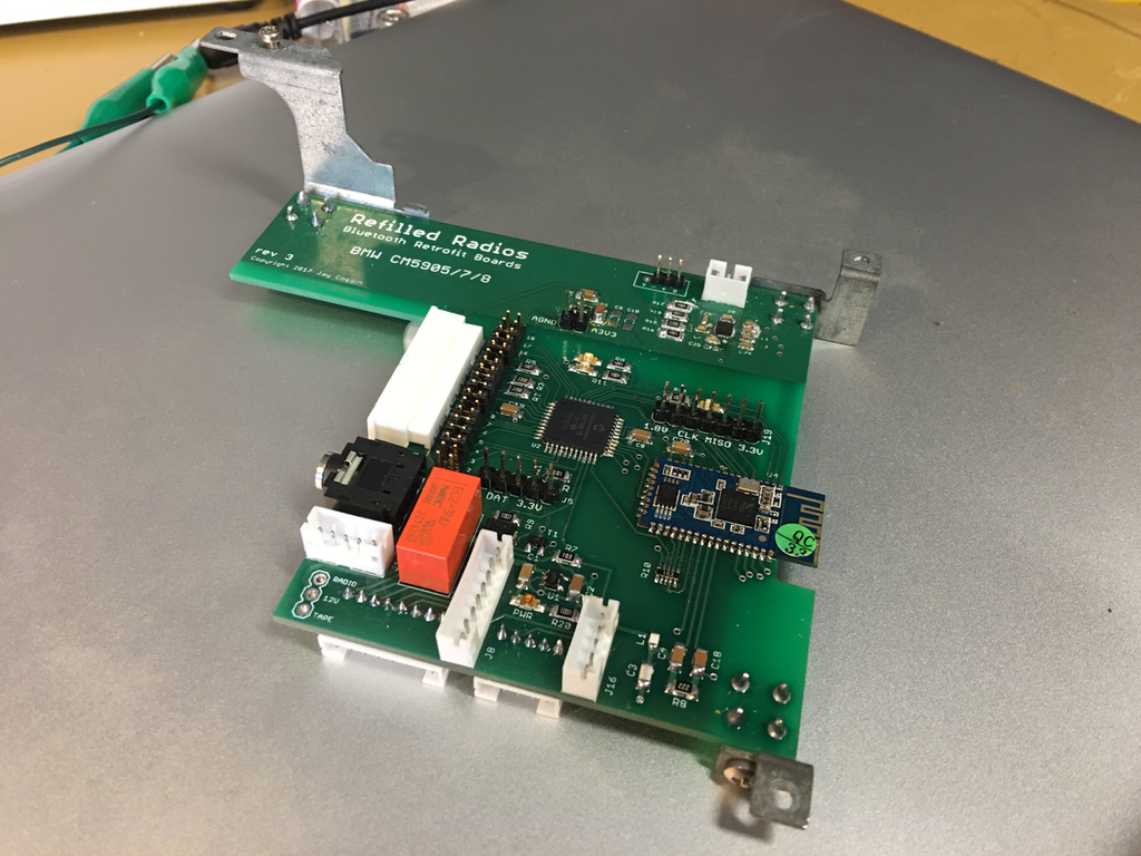
    This has most of the hardware to support the 5907 as well, hence more connectors. Still indecisive on the name, even though I threw "Refilled Radios" on this one. You gotta try these things on. I've also thrown around (my current favorite) Big Button Audio, Inside Out Audio, or Inside Out Radios.

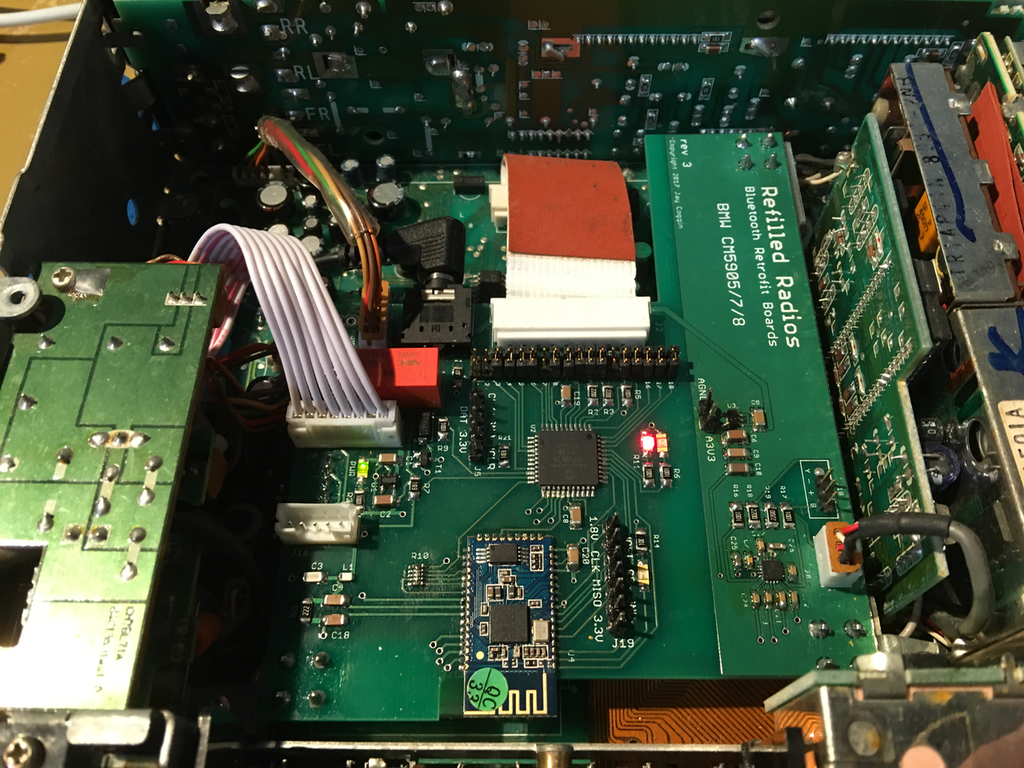
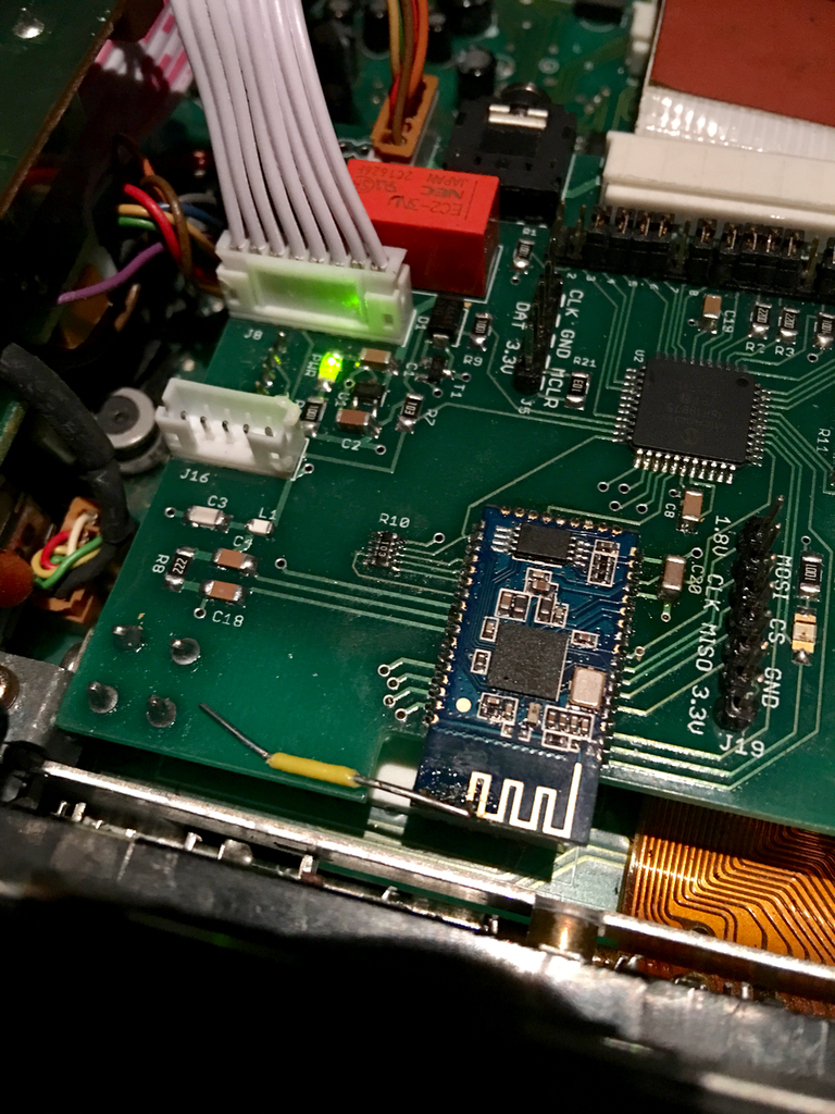
    Mounted in the 5908:


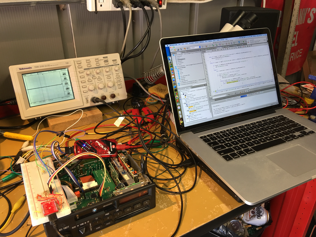
    Here's the debug and firmware-work setup. The Mac runs the PIC IDE connected to the programming header with their USB programmer, then a homebrew programmer on a breadboard for the CSR BT chip hooked up to the bottom Mac (running Windows for their configuration tool).


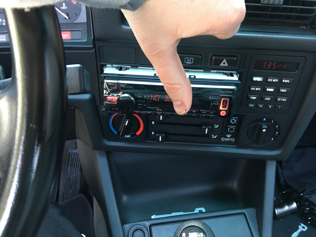
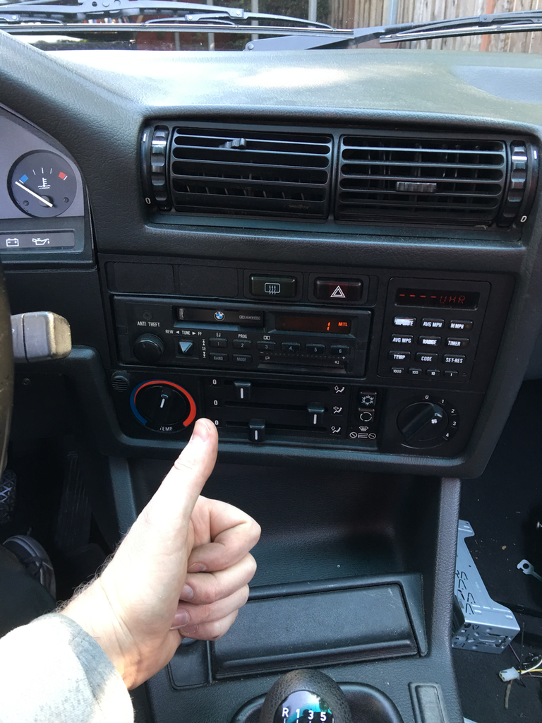
    Buttoned up the last of the known issues this morning and got on to the best part: finally installing it in my car.


    DEATH TO CHEESY PLASTICS AND BLINKY LIGHT SHOWS!!!


    Most of the install was painless, I had gotten one radio with its harness, which I had to reinstall in my car. I'm going to try and see what I can do to find suitable replacement speaker connectors though, unless someone knows of some? I assume some people will need those since they don't seem to be standard.

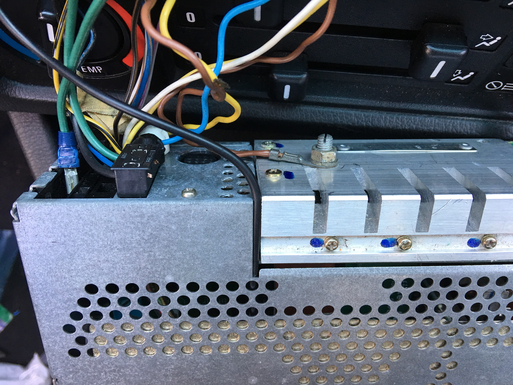
    The only issue I found was that the dash hole for the radio is seriously tight, so much that I snagged and shred a microphone cable by coming out the side of the chassis and trying to run it back along the side of the radio. Instead, here's where I ended up running it, which actually seems to work well, just have to make sure there's no burrs on the top lid:


    And finally, much improved!


    Drove around a bit rockin out, made a phone call, tried all the things, everything is working peachy. It was a good day. Going to try to nail down the last of this digital noise for the next board rev, but I'm going to go ahead and make the other edits for IT (analog stuff for the 5907 and removing some extra debug gear). I've got 3 people who have spoken up wanting to be part of the first round beta, I would do one more if someone wants to participate with feedback and possibly having to swap out boards if there are issues, etc. I'll plan on making 5 boards, hand-assemble them, and get em out to this first round of folks! Goal is to be sending those out by May 1.

    Comment


      #62
      I don't know what to say because I can't even get my fog light to work. Nice work..
      sigpic
      327is
      325es
      325es
      318is
      Fiesta ST
      E46 M3

      Comment


        #63
        Originally posted by jaysterling View Post
        DEATH TO CHEESY PLASTICS AND BLINKY LIGHT SHOWS!!!
        ;D

        hot damn Jay. ready to go on this end :-)
        looking forward to showing one off at The Vintage next month.
        I'll be rocking mtech1 and shadow line trim on my vert too.
        I BUY/SELL REFURBISHED CM5907s & CM5908s

        HOWTOs:
        DB vert plastic bumpers
        OEM Keys
        MTech1 docs

        88 ix Lach/Card
        91 ic Calypso 3.1
        86 Cosmo 2.7

        OEM+ or bust!


        reelizmpro: I will always be an e30 guy.. I still do all of my own labor
        TrentW: There's just something so right about a well-built M20 in an E30
        e30m3s54turbo: I save my money for tuner parts.

        Comment


          #64
          When do you think this will be a product that I can buy? I'm ready to throw money at you, I'm so tired of my shitty red and orange head unit.

          Comment


            #65
            Originally posted by Appleseason View Post
            When do you think this will be a product that I can buy? I'm ready to throw money at you, I'm so tired of my shitty red and orange head unit.
            My current best guess would be the start of July. If I ship out the first boards May 1, hopefully they're installed that weekend and people have a good week to live with it, so that goes through mid-May. Assuming there are no significant issues, I'll go ahead and have the first run of the boards fabbed + assembled in China will add something like 4-6 weeks.

            Comment


              #66
              What are you using for filter caps and 3.3V supply (LDO?) for that CSR dongle? I'm using mine in a mesh application, and saw seriously nasty current switching as the chip switches from send to receive. I had to stick a ton of capacitance to clean things up for the rest of my design, 270uF caps. Could be the source of your "digital noise." The switching was relatively low frequency, so I could imagine it being in the audio spectrum. You've got a lot of space on that board, have you tried just brute forcing the filtering?

              I'd be happy to look things over if you'd like, not sure what you have going for IP or non-disclosures right now. I'm a power supply engineer in the lighting business, working on wireless controls.

              Are you using an XC8 compiler for your PIC? Saves a lot of space, they give you a free month trial for it.
              Last edited by earthwormjim; 04-10-2017, 12:20 PM.

              Comment


                #67
                Originally posted by jaysterling View Post
                Assuming there are no significant issues, I'll go ahead and have the first run of the boards
                Thumbs up! Wish more more people took the time to go slow and make sure it works right rather then rushing to cash.
                Originally posted by Matt-B
                hey does anyone know anyone who gets upset and makes electronics?

                Comment


                  #68
                  Looks great Jay!!

                  Comment


                    #69
                    Originally posted by earthwormjim View Post
                    What are you using for filter caps and 3.3V supply (LDO?) for that CSR dongle? I'm using mine in a mesh application, and saw seriously nasty current switching as the chip switches from send to receive. I had to stick a ton of capacitance to clean things up for the rest of my design, 270uF caps. Could be the source of your "digital noise." The switching was relatively low frequency, so I could imagine it being in the audio spectrum. You've got a lot of space on that board, have you tried just brute forcing the filtering?

                    I'd be happy to look things over if you'd like, not sure what you have going for IP or non-disclosures right now. I'm a power supply engineer in the lighting business, working on wireless controls.

                    Are you using an XC8 compiler for your PIC? Saves a lot of space, they give you a free month trial for it.
                    Thanks for the offer Jim. So I'm using 2 identical 3.3V LDOs, one for all the digital stuff, one for the headphone amp that does the differential to single-ended conversion. Both have a 1 uF cap on the input side, 2.2uF on the output side. On the analog one, I have an additional 10 uF and 0.1uF on the output.

                    One thing that helped isolate noise a lot was to have the analog section ground through the mount points/chassis rather than through the ground in the power connector, which is what the digital section grounds through. Even doing a "star ground" where the analog and digital grounds only meet right at the connector still produced a lot of noise. Both supplies are fed from the same 12V power pin though, so my thought was maybe stick a ton of capacitance between that 12V power pin and ground right where it hits the board? Is that what you mean by "Brute forcing it", i.e. throw a bunch of capacitance at it?

                    I am using the free version of the XC8 compiler. I guess it's less optimized than the Pro version, but the price increase per chip is cheaper than a Pro license right now.

                    Comment


                      #70
                      Originally posted by jaysterling View Post
                      Thanks for the offer Jim. So I'm using 2 identical 3.3V LDOs, one for all the digital stuff, one for the headphone amp that does the differential to single-ended conversion. Both have a 1 uF cap on the input side, 2.2uF on the output side. On the analog one, I have an additional 10 uF and 0.1uF on the output.

                      One thing that helped isolate noise a lot was to have the analog section ground through the mount points/chassis rather than through the ground in the power connector, which is what the digital section grounds through. Even doing a "star ground" where the analog and digital grounds only meet right at the connector still produced a lot of noise. Both supplies are fed from the same 12V power pin though, so my thought was maybe stick a ton of capacitance between that 12V power pin and ground right where it hits the board? Is that what you mean by "Brute forcing it", i.e. throw a bunch of capacitance at it?

                      I am using the free version of the XC8 compiler. I guess it's less optimized than the Pro version, but the price increase per chip is cheaper than a Pro license right now.
                      Yes, try dumping a bunch of capacitance into the circuit, see if that helps, that's what I meant by brute force. You can never have too much capacitance, especially if you have the space.

                      10uF is not a whole lot at 3.3V. CSRs design references just give bare minimum values to get things working, not what works well... Remember CV^2 relationship, so you have the right idea to start at the 12V. I have access to tons of through hole aluminum caps, let me know if you want me to send you some samples, definitely interested in this project taking off.

                      That's good you are using separate regulators, and LDOs are super clean. You could also add some small impedance (5-10 ohm) feeding the bluetooth module's LDO (or just after it), then put capacitance on its 3.3V. I've had luck putting low resistors between grounds too, floating the bluetooth module with 1-5 ohms on its ground could help. Noise is mysterious...
                      Last edited by earthwormjim; 04-12-2017, 11:47 AM.

                      Comment


                        #71
                        Originally posted by jaysterling View Post
                        Is that what you mean by "Brute forcing it", i.e. throw a bunch of capacitance at it?
                        We use to call it a "BFC". Big freaking cap. :devil:

                        Originally posted by earthwormjim View Post
                        LDOs are super clean. Y
                        Really? More then just a regular linear regulator?
                        Originally posted by Matt-B
                        hey does anyone know anyone who gets upset and makes electronics?

                        Comment


                          #72
                          Yes, please contact me if you get this going!

                          Comment


                            #73
                            Originally posted by george graves View Post
                            We use to call it a "BFC". Big freaking cap. :devil:


                            Really? More then just a regular linear regulator?
                            LDOs are linear regulators, just they usually use FETs instead of BJTs as the pass element.

                            Comment


                              #74
                              In for one of these
                              Continuous For Sale Thread
                              323i s50

                              Comment


                                #75
                                Thanks for the suggestions guys, I gave them all a shot today. I tried all kinds of caps everywhere, up to like 260 uF ones, none made any noticeable difference in my case. I was trying all kinds of stuff swapping what was grounded where and trying to further separate the power supplies, thinking the noise was coming from digital switching currents. None of that changed anything either. BTW, this noise that's left is 2 successive ticks happening at 40 Hz. All the high-frequency buzzy stuff was fixed with power supply/ground separation earlier.

                                I then had a few discoveries that led me to the problem. First, and I can't believe I hadn't tested this, but I unplugged just the audio out cable from the board, cranked the volume, and the noise was still there! So it's not coming from my audio circuit, it's getting into the final output simply if the BT chip is on and connected. Then I started grabbing around the board with my hands and noticed changes and decreases in the noise. Eventually, I put my finger right on the BT chip antenna and bingo - gone! And after spending a ton of hours today trying to track this thing down, this little yellow wire fixes it:


                                Yes, that's a piece of wire maybe an inch long soldered to the chip antenna that goes nowhere. Total black magic... But seriously, my best guess at what's going on is the noise is due to RF interference from the antenna, and the tiny piece of wire is enough to move the signal traffic a little farther away from the audio circuitry? My finger was sort of doing the same, or at least just making RF unable to reach the antenna (since I'm a poor conductor)? Let me know if I'm way off.

                                So at least I kinda know the general area of the problem now and a way to fix it. Problem is how to fix it the non-hacked way. I can definitely move the BT chip over farther to that side of the board where the yellow wire runs to, and I can use the ground planes more aggressively around the antenna to try to contain the RF traffic to that little area, but it just seems tough to really be sure it's fixed before spinning another board and trying it.

                                Comment

                                Working...
                                X