
Nice work so far can't wait to see the finished valve cover
-
1989 JDM-Tech 2
2010 335 D for daily -
Me limey whats going on here
Comment
-
Small update
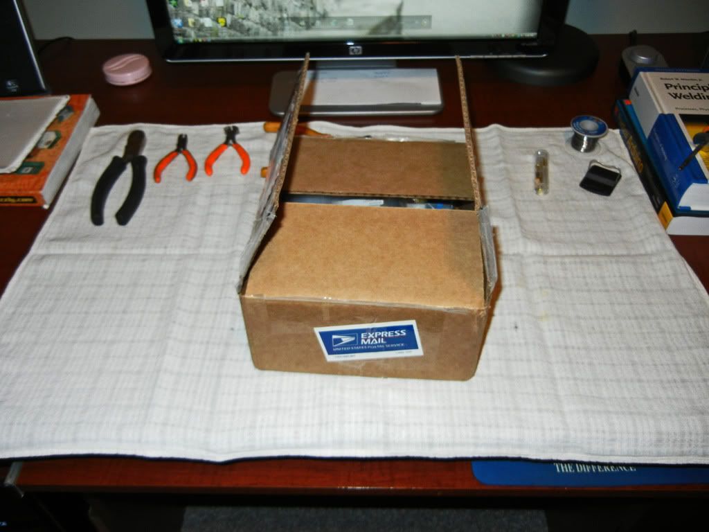
This arrived in the mail yesterday...
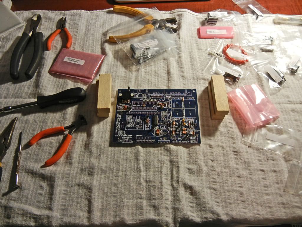
Building...and yes I used Jenga blocks to prop up the board while I was inserting the components with the long leads. Then I put that piece of Styrofoam from a ground beef package on top to hold the components in place while I flipped the board over. Then I soldered and trimmed the leads. A good bit of precision engineering really...
Between last night and this evening I got the kit built, I just need to get some vacuum line for the map sensor, load the firmware and maps and then (hopefully) fire up the car and get it running well on the kit ahead of time.
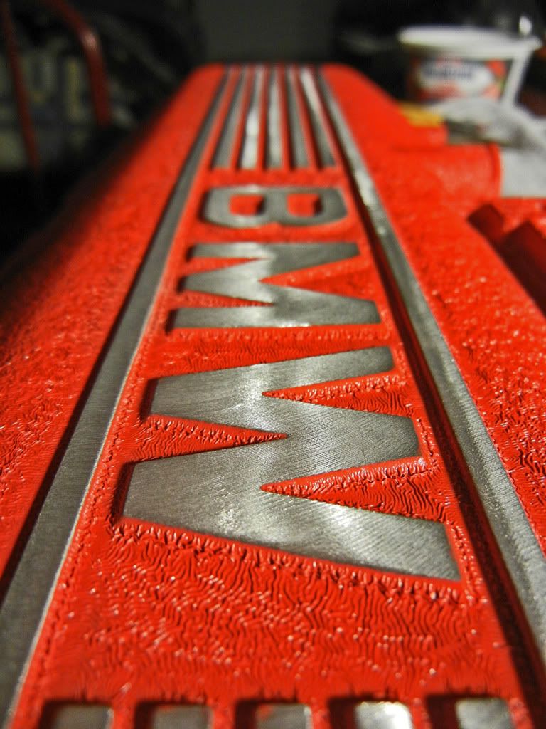
I also buffed the valve cover today, I'm happy with the way it turned out...
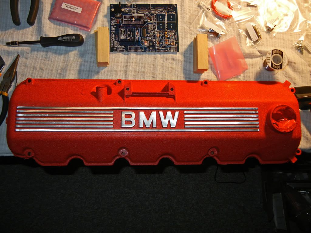
My mom would probably tell me I need to iron my valve cover...

Comment
-
that valve cover looks awesome.
Comment
-
looks great man! really good stuff.
one reason why rougher surfaces flow better is the same reason a golf ball has dimples. the rough surface traps air onto it and creates an air to air boundary layer. the flowing air flows over the trapped air a lot easier than the metal.AWD > RWDComment
-
Looking great! I dig that valve cover.
On a scale of 1-10 how hard would you say building a MS box is? I haven't decided if I want to buy a premade box or build my own.-AlexComment
-
Define the range of the scale for me ;)Originally posted by acolella76 View Post
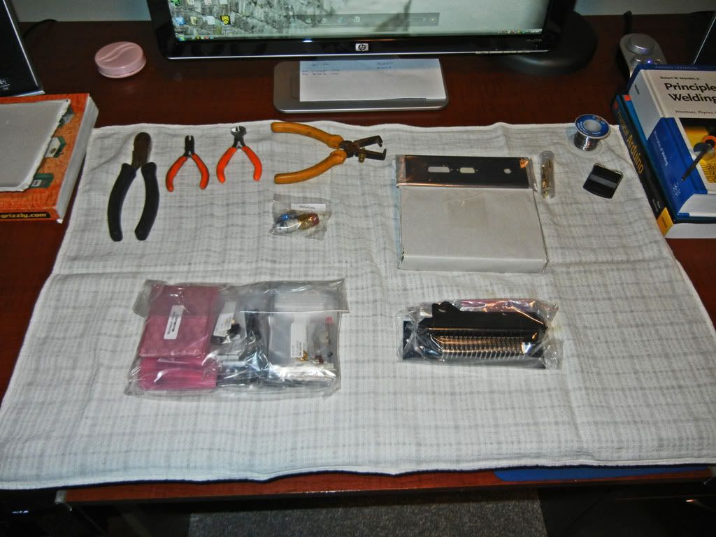
I'll say this, if you can build a motor you can build this kit. You just need some patience, a soldering iron with a nice small tip, and some good solder. The first time I built one I did it in a weekend. This time around I did it in about 4-5 hours between two evenings. You don't even have to use most of the components that come with it, when you first unpack the kit it it looks a lot more daunting than it actually is because there are a lot of components.
You just figure out what circuits you need to build and then follow the general assembly procedure on the website but only install the components you need. If you look at this picture...
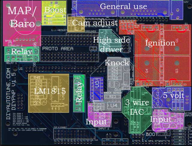
You don't need the boost control circuit (unless you plan on boosting :p), cam adjust, LM1815, or knock. As you can see that doesn't leave very much to install. Most of the work is done by the microsquirt module which comes pre-built.
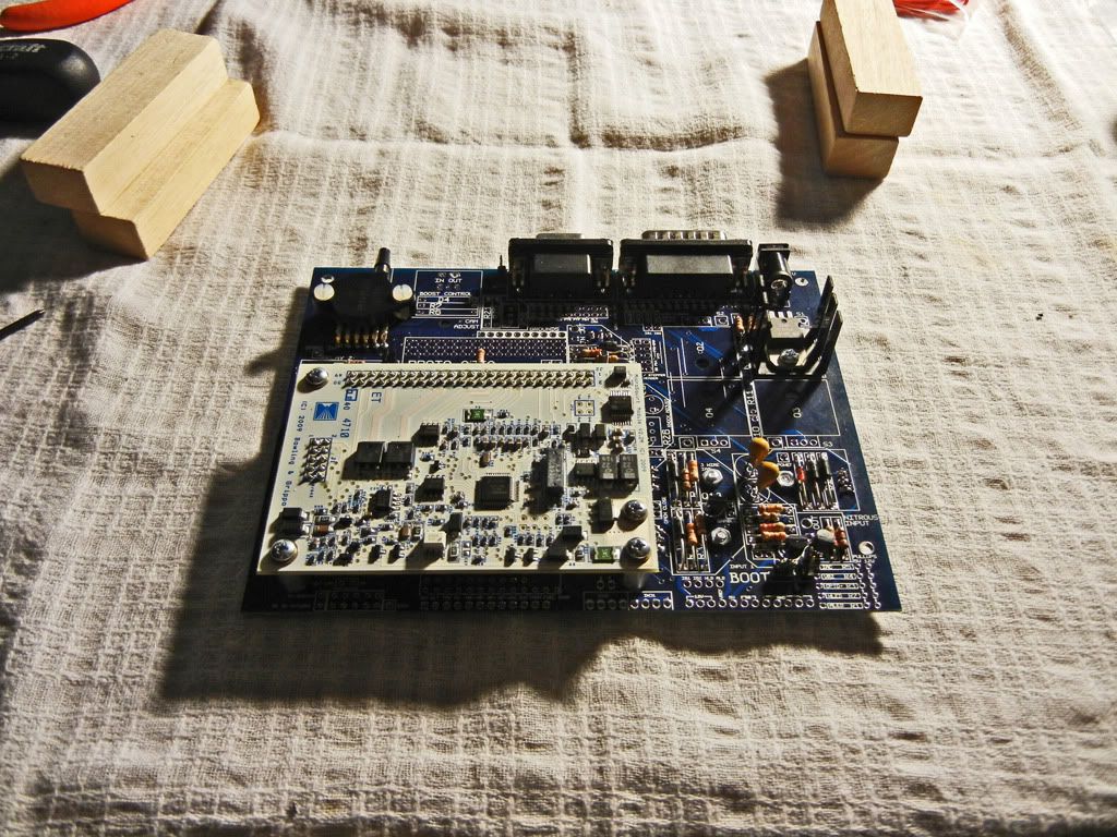
This is a picture of the board with all the components you need installed (minus the LM1815 circuit) before you solder on the header for the microsquirt

Then you install the microsquirt module...

Then the hardest part is doing the jumpers because keeping the wires in place while you try to solder them can be finicky...

Comment
-
If you have experience soldering things before it's not to bad. Some of the components are pretty small, but none of it is sms. If you haven't really soldered anything else before I would probably practice on a less expensive project before hand just to make sure you really have the hang of it.Comment
-
Great thread, I love in depth stuff.
Curious, your screen name reminds me of an In Flames song, are you a metalhead?Comment
-
-
Thirdly, I was thinking about the adjustable cam gear yesterday and how I would go about making adjustments. All the after-market gears have a degree scale etched into them, but I don't have the tools to do that. I thought about just printing a scale that I could just laminate and glue on and use with the existing timing line on the gear, yeah kind of ghetto but it would work. Then I thought about how pretty much all mechanical timing adjustments rely on the accuracy of the eye of the person making the adjustment. I figured it’d be nice if there was a quick, easy, and above all fool proof way to make timing adjustments. I came up with this concept…
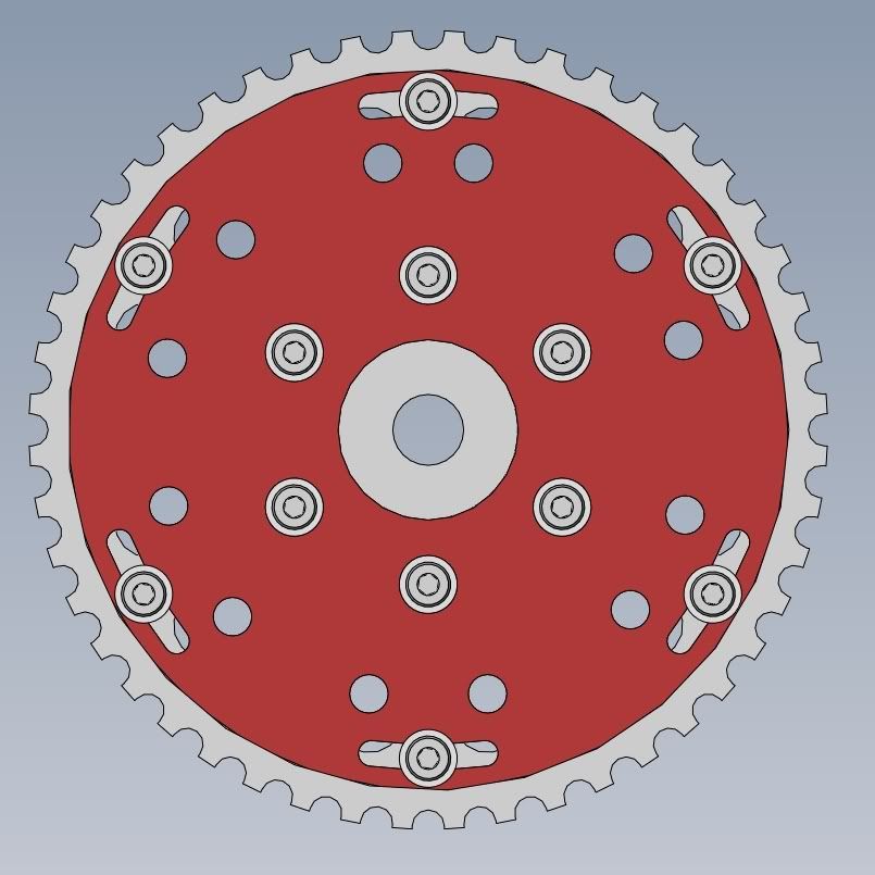
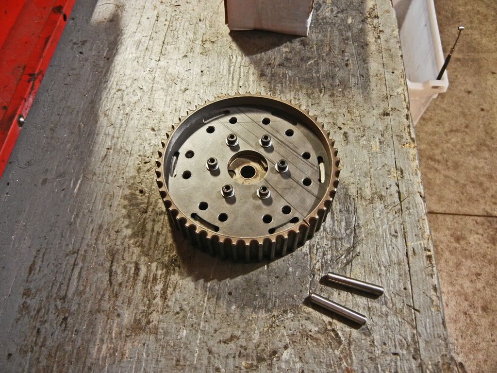
At this point you might be wondering what those extra holes are for. Looking at the timing gear I figured that the manufacturing tolerance of the gear was at least as good as (or better) than the accuracy of the human eye so why not use the physical geometry of the gear to dictate the timing adjustment. Obviously when I go to machine the gear I will verify if my assumption was acceptable or not. This picture will give you a better idea of what is going on…
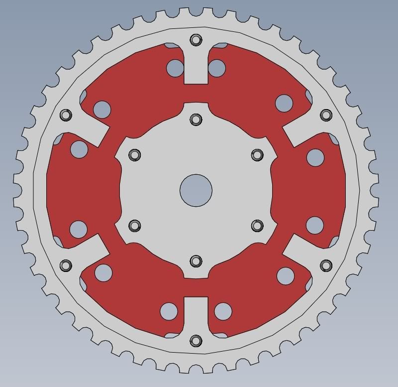
As you can see, my idea was to use the spokes of the timing gear to adjust timing. The holes in the plate will be reamed to 6mm to have a nice snug fit for a 6mm dowel pin. That way I will be able to insert a dowel pin into a hole, loosen the screws around the outside and rotate the gear until the dowel pin contacts the spoke. One spoke is used to set the orientation of the gear back to stock timing and the other spokes can advance or retard the timing 1 degree per spoke. So this layout gives me +/- 5 degrees of timing adjustment on the cam which correlates to +/- 10 degrees on the crank, however the holes could be revised to give any combination of advance and retard. Hopefully it works!
That’s all for now folks!Last edited by Bullet Ride; 05-23-2013, 08:33 AM.Comment
-
You must think you are soooo smart coming up with that ^^^
And you would be right!
Could the uneven spacing of the holes cause an imbalance?sigpic
1988 Lachssilber E30 325i sedan.
Factory fit-out: manual; SILBER LEDER; M SPORT SUSPENSION.
Modifications so far: Miller MAF + 19# ECU; Ford 19# Design 3 injectors; IE adjustable FPR; KAMotors CF airbox; IM MTX-L; EBC Greenstuff.
Retired - '83 Arctic Blue E28 528i powered by M30B32
Comment
-
Technically yes, but since the largest variance in hole location from side to side is only +/- 3 degrees on a short radius and the amount of material being removed is pretty small relative to the overall weight the result is that the center of gravity shifted off of the rotational axis by 0.006mm... so pretty much nothing :-)Originally posted by BMW_325i View PostComment
-
Update time:
Much to my excitement I came home from work today to find a big ol' pile of parts in the garage...
This was sitting on the work bench...
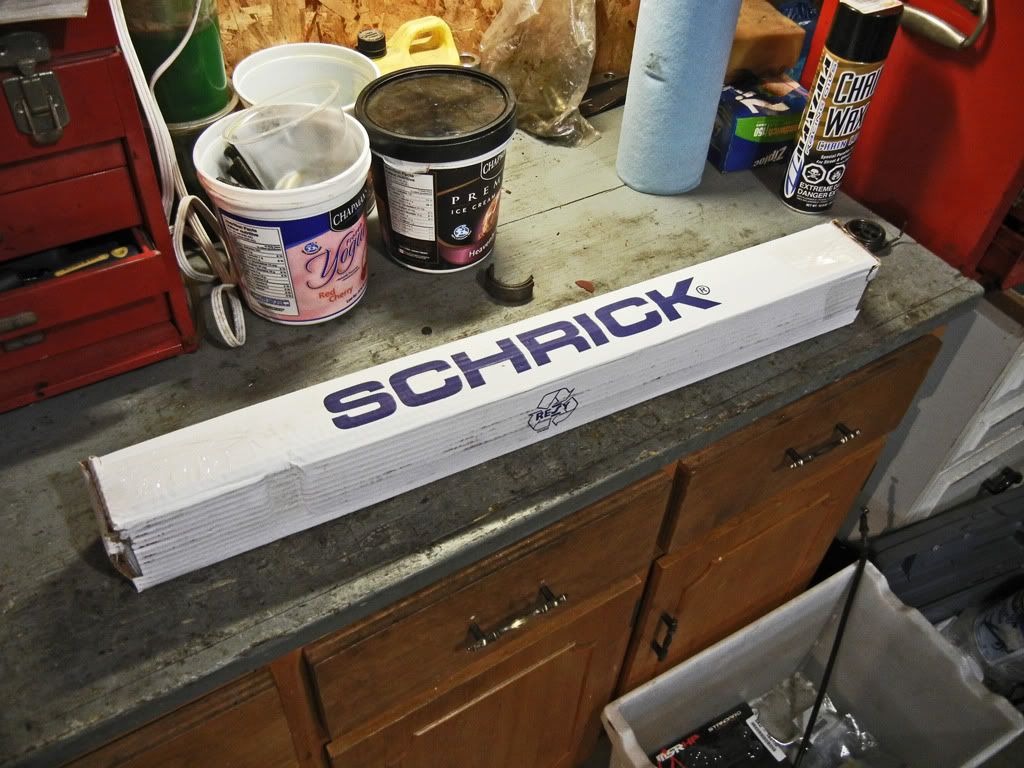
Ask an oriental man to say slick and it'll sound like....
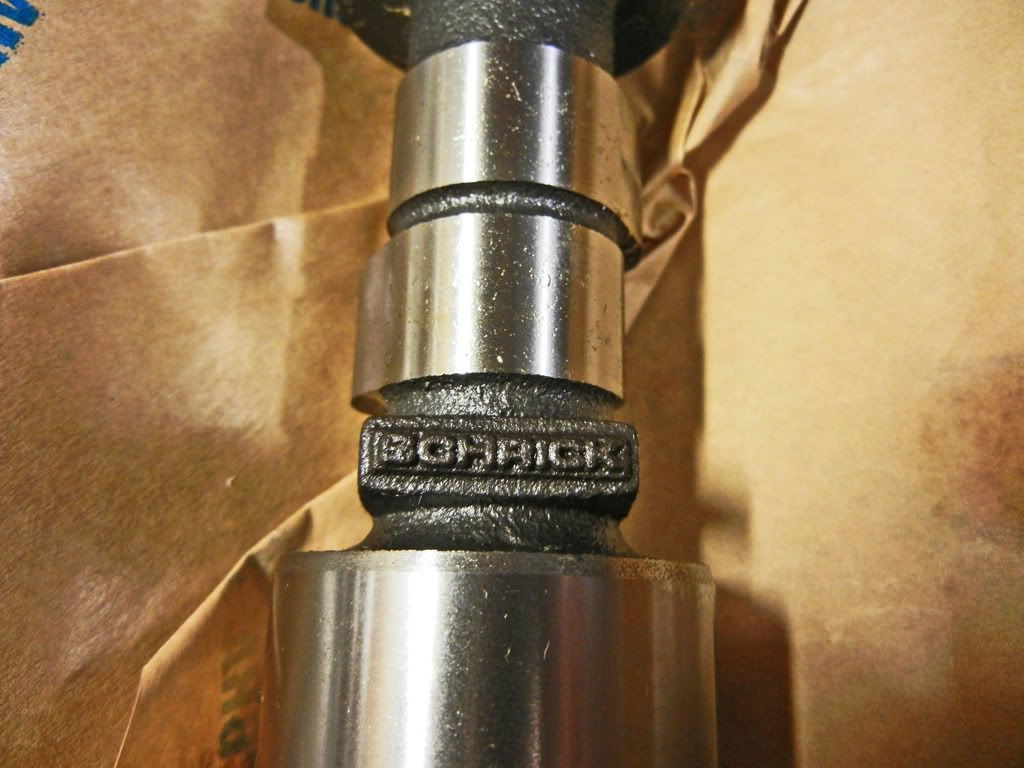
That's a Schrick looking cam...
(p.s. I've got plenty of oriental friends so I feel like I can make that joke lol)
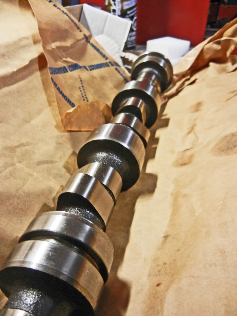
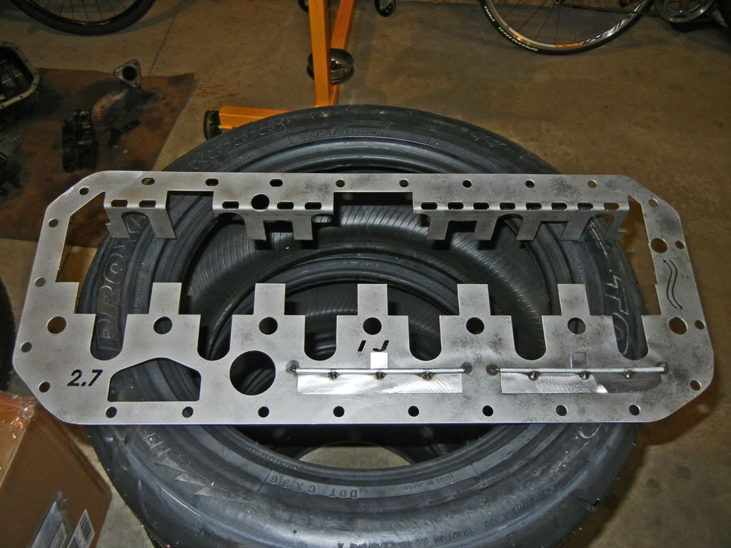
Next up is the #becauseracecar part. I ordered the 2.7 scraper because it's stroke is close to the 2.8 crank. I'll need to adjust the clearances a bit so it won't rub
And the rest of the internals, seals, hardware, etc...
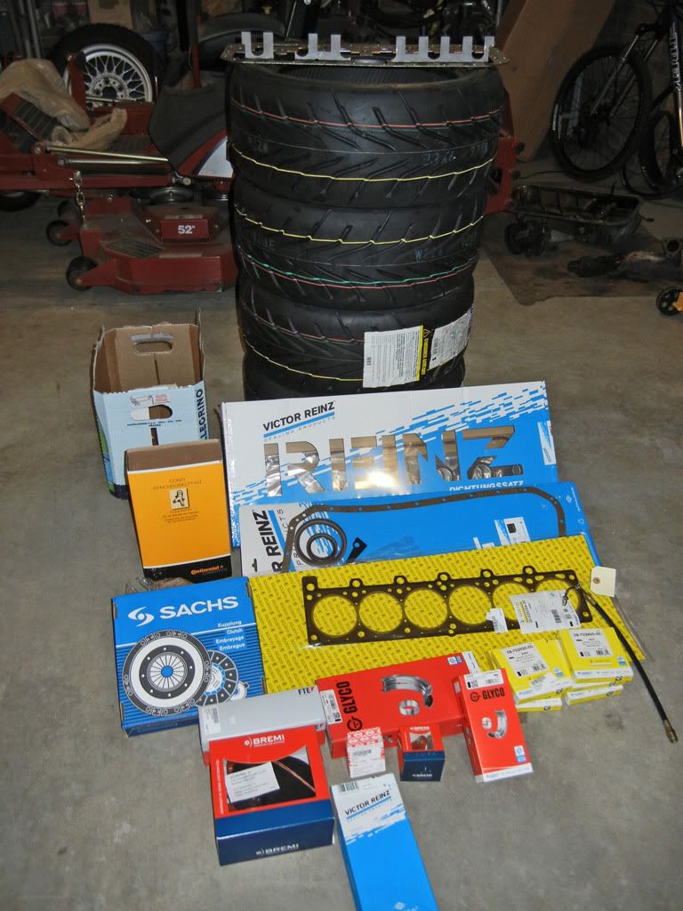
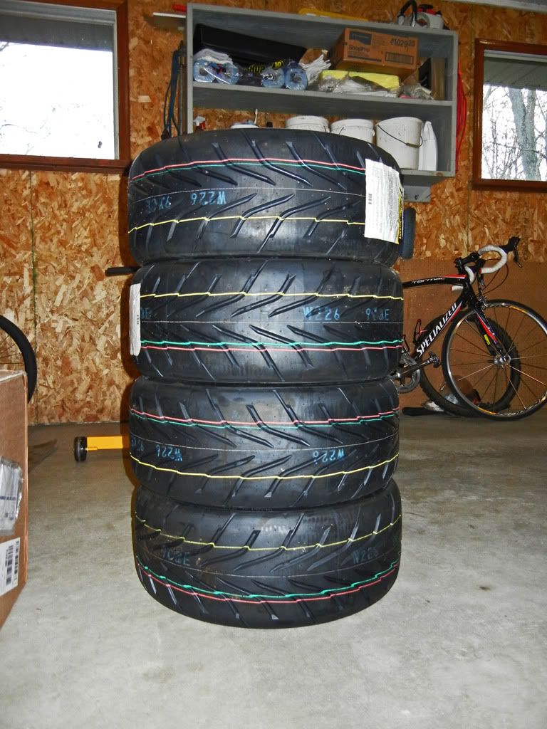
And yes you saw correctly, all those bits were sitting in front of a stack of new Toyo R888s which I got a wicked deal on...
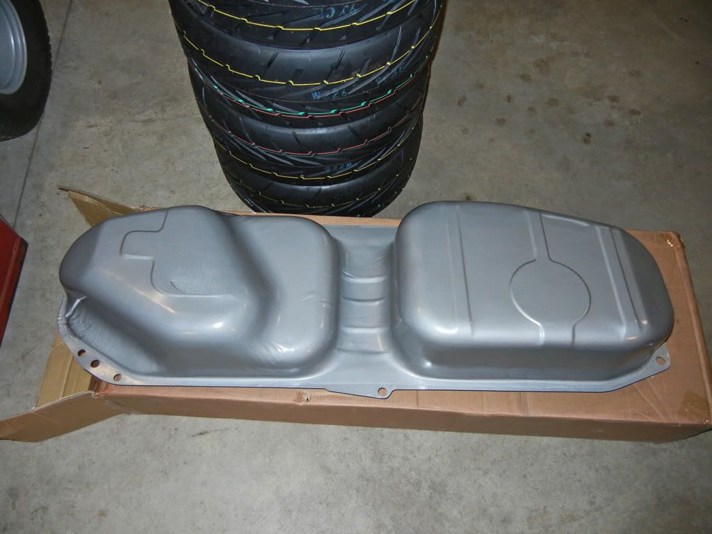
And not directly related to the engine build, but still important...
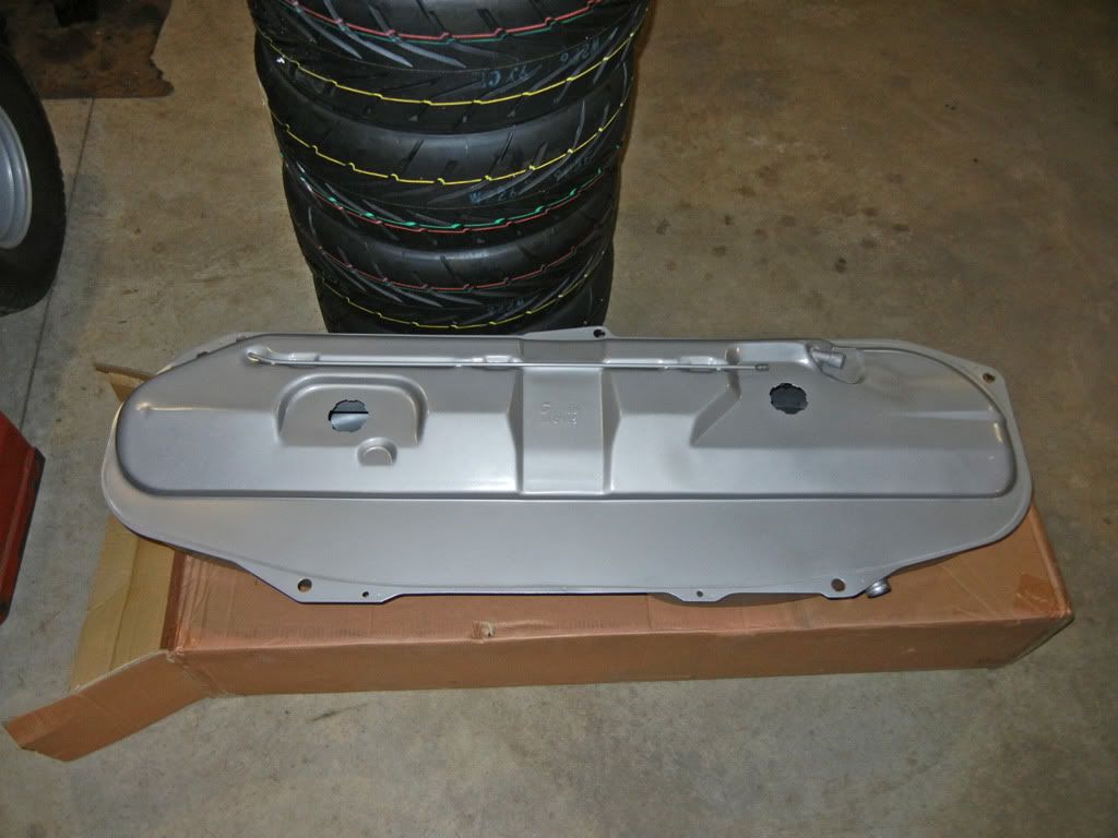
My current tank has a hole rotted on the top left side somewhere because when it's more than half full a quick left will leave the cabin with the smell of spilt gas. I figured if I'm going to be dropping the exhaust and drive shaft to swap the motor it will be as good a time as any to swap the tank out...
And to finish off the update, I'm almost done making the adjustable cam gear. I just need to drill and tap the holes around the outside and then separate the gear into two pieces...
I'm going to try and get the head assembled this weekend and then finish up the cam gear on Monday so I can work on setting the timing and checking the valve to piston clearance next week.Comment
-
Did you get those R888's on eBay for $420?
lulz just realized how many questions i've been asking in this thread. Keep up the good work! I love those tires, they head up instantly. I've been using them for track and autocross duty, and if i had the money i would use them for summer as well.Last edited by acolella76; 04-27-2012, 07:07 PM.-AlexComment

Comment