
Here's the link: http://forums.bimmerforums.com/forum...77#post7482777
This is in a 99 m3, so there are a couple differences. The oil pan i.e
Copy and pasted most of this from Bimmerforums...I thought it was a good informative post for OBD2 to OBD1 converters (thanks vinnymac)
My OBD1 conversion is finally done. Whew...it was quite an involved process and don't let anyone fool you by saying it's "just an electronics swap."
I spent a lot of time researching bimmerforums.com and consulting with a few people that had done it in the past along with many hours staring at wiring schematics in the Bentley manual.
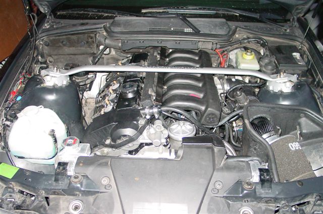
Here's what my OBD2 S52 looked like before I began the conversion:
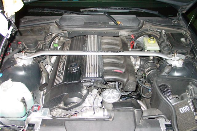
My car is a 99 M3 with OBD2 management and EWS (BMW anti-theft). I sourced an OBD1 engine harness from a 94 325i along with red-label 413 ECU. The chip I'm using is from Active Autowerkes.
The general stuff you need:
1. OBD1 harness
2. OBD1 ECU (413 "red label" preferred b/c they come from non-EWS cars).
3. OBD1 chip
4. OBD1 intake manifold
5. OBD1 fuel rail
6. OBD1 crank position sensor
7. OBD1 cam position sensor
8. OBD1 ping/knock sensor x2
9. OBD1 oxygen sensor
10. OBD1 HFM
11. OBD1 main engine coolant hose (big hose that connects to the coolant pipe fitting on the timing cover, heater core, and radiator expansion tank)
12. OBD1 throttle boot
13. OBD1 throttle body (optional)
14. OBD1 valve cover and coil packs (optional)
The conversion sounds conceptually simple but there are a lot of little things that need to be addressed.
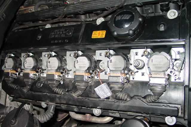
1. Valve Cover - The OBD2 valve cover does not have provisions for routing the coil pack connectors because the OBD2 cables enter from the passenger side and the OBD1 cables enter from the driver side. This is where you need to decide which route to go. You can keep your OBD2 valve cover, which allows you to keep your OBD2 coil packs or you can use an OBD1 valve cover which will require OBD1 coil packs. Either way is fine since both coil versions plug into the OBD1 harness. I choose to keep my OBD2 valve cover and will modify it slightly with a Dremel to route the wiring.
Here's a pic of the OBD2 setup:
Here's a pic of the OBD1 setup:

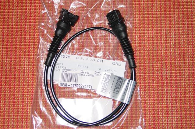
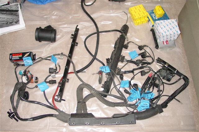
2. Vanos Solenoid - You don't need to get the vanos solenoid harness extensions.
Here's a picture of the harness:
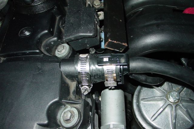
3. Coolant Pipe - The main coolant pipe from the timing cover (back side of the t-stat housing) is different between OBD1 and OBD2. OBD2 cars use a metal pipe that is fixed in the timing case cover with plumbers sealant. OBD1 cars use a rubber hose that connects to an aluminum neck that protrudes from the timing case cover. You can either use an OBD1 timing cover ($100) or get a coolant pipe adapter ($20) from Bimmerworld, AA, or Turner Motorsport. The coolant adapter fits into the OBD2 timing case cover and is secured with JB Weld. This allows you to pipe clamp the OBD1 coolant hose.
Here's a picture of the coolant pipe adapter: (it's the aluminum pipe right below the oil filter housing)
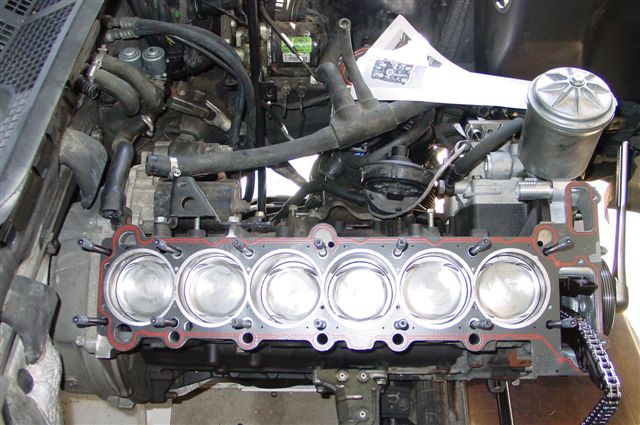
4. Intake Manifold – This is where the “performance gain” from an OBD1 conversion comes from. The M50 intake manifold flows better than the OBD2 (M52/S52) intake manifold. You must use this manifold for the conversion. The OBD1 manifold will have a air temp sensor and vacuum port for the fuel pressure regulator on the underside closest to the firewall. The M50 intake manifold will bolt right up to an M52/S52 cylinder head without modification.
5. Throttle Body – You can use your OBD2 throttle body but you will need an adapter for the gasket seal. The OBD1 throttle body has a flat mating surface that clamps to a gasket on the OBD1 intake manifold. The OBD2 throttle body is the opposite and has a gasket in the throttle body that clamps to a flat mating surface on the OBD2 intake manifold. You can solve this problem two ways. You can get an adapter plate ($20) that sits between the OBD2 throttle body and OBD1 manifold, which provides a mating surface for both gaskets. The other option is a get an extended gasket ($15) that allows you to clamp the OBD2 throttle body directly to the OBD1 intake manifold. Of course, you can always use an OBD1 throttle body and not use any adapters.
6. Coolant Temp Sender – OBD2 management uses a single coolant temp sender on the cylinder head under the intake runner for cylinder #1. The OBD1 setup uses two temp senders on the cylinder head under intake runners #1 and #2. You can splice the main engine harness wiring together and use the OBD2 plug connector from your old wiring harness to connect to your single OBD2 temp sender. Another option, which is much cleaner, is to use the coolant temp sender wiring adapter ($50) from Turner Motorsport that is completely plug and play.
7. Crank Position Sensor – The OBD2 crank position sensor is located on the engine block in front of the starter motor. The OBD1 crank position sensor is located on the timing cover and mounts on a circular tab with a 6mm allen bolt. You must use an OBD1 crank position sensor. Just leave the OBD2 sensor in place to plug the hole.
8. Fuel Lines – The fuel delivery setup is significantly different between OBD2 and OBD1. The OBD2 fuel rail has both fuel lines attaching in the rear near the firewall and the fuel pressure regulator is located forward of the fuel filter under the driver side of the car. The OBD1 fuel rail has the supply line on the front of the rail and the return line on the back of the rail near the fire wall. In addition, the OBD1 fuel pressure regulator is on the fuel rail itself next to the return line. You must use the OBD1 fuel rail for the conversion, which will require modification to the fuel lines. You will need to remove the OBD2 fuel pressure regulator from the undercarriage of the car and route new 8mm fuel lines to the OBD1 fuel rail. There is a pair of hard lines mounted to the chassis between the OBD2 fuel filter and engine bay. Simply bridge the gap left by the removal of the OBD2 fuel pressure regulator with new fuel line and connect the feed from the fuel filter to the front of the OBD1 fuel rail and the return line from the back of the fuel rail to the return line under the car. You will also need to connect the OBD1 fuel pressure regulator vacuum line to the one-way valve on the bottom of the OBD1 intake manifold. The connection is on the back corner of the manifold closest to the firewall.
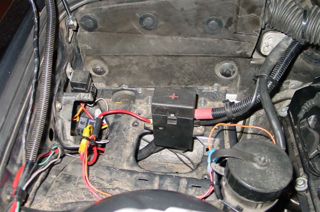
9. PCV – The OBD2 crank case vent is setup up differently than the OBD1 vent. There are several options to address this issue. If you are using the OBD2 valve cover, you can keep your OBD2 PCV setup and figure out a way to mount the breather valve (cone shaped plastic valve with round breather on top) under the intake manifold. If you are using the OBD1 valve cover, you should use the OBD1 breather valve that clips on to the crankcase vent port. The OBD1 valve has a vacuum line that connects to the plug that joins the ICV to the intake manifold and a large oil drain line that runs to the dipstick. The last option is a hook up a hose to the crankcase vent and run a breather catch can. I picked up a small length of 1” rubber hose and connected it to my OBD2 valve cover and hooked up the other end to the OBD1 breather valve and use a barbed connector to join the oil drain line to my dipstick.
Here's how I hooked it up:
This is in a 99 m3, so there are a couple differences. The oil pan i.e
Copy and pasted most of this from Bimmerforums...I thought it was a good informative post for OBD2 to OBD1 converters (thanks vinnymac)
My OBD1 conversion is finally done. Whew...it was quite an involved process and don't let anyone fool you by saying it's "just an electronics swap."
I spent a lot of time researching bimmerforums.com and consulting with a few people that had done it in the past along with many hours staring at wiring schematics in the Bentley manual.
Here's what my OBD2 S52 looked like before I began the conversion:
My car is a 99 M3 with OBD2 management and EWS (BMW anti-theft). I sourced an OBD1 engine harness from a 94 325i along with red-label 413 ECU. The chip I'm using is from Active Autowerkes.
The general stuff you need:
1. OBD1 harness
2. OBD1 ECU (413 "red label" preferred b/c they come from non-EWS cars).
3. OBD1 chip
4. OBD1 intake manifold
5. OBD1 fuel rail
6. OBD1 crank position sensor
7. OBD1 cam position sensor
8. OBD1 ping/knock sensor x2
9. OBD1 oxygen sensor
10. OBD1 HFM
11. OBD1 main engine coolant hose (big hose that connects to the coolant pipe fitting on the timing cover, heater core, and radiator expansion tank)
12. OBD1 throttle boot
13. OBD1 throttle body (optional)
14. OBD1 valve cover and coil packs (optional)
The conversion sounds conceptually simple but there are a lot of little things that need to be addressed.
1. Valve Cover - The OBD2 valve cover does not have provisions for routing the coil pack connectors because the OBD2 cables enter from the passenger side and the OBD1 cables enter from the driver side. This is where you need to decide which route to go. You can keep your OBD2 valve cover, which allows you to keep your OBD2 coil packs or you can use an OBD1 valve cover which will require OBD1 coil packs. Either way is fine since both coil versions plug into the OBD1 harness. I choose to keep my OBD2 valve cover and will modify it slightly with a Dremel to route the wiring.
Here's a pic of the OBD2 setup:
Here's a pic of the OBD1 setup:
2. Vanos Solenoid - You don't need to get the vanos solenoid harness extensions.
Here's a picture of the harness:
3. Coolant Pipe - The main coolant pipe from the timing cover (back side of the t-stat housing) is different between OBD1 and OBD2. OBD2 cars use a metal pipe that is fixed in the timing case cover with plumbers sealant. OBD1 cars use a rubber hose that connects to an aluminum neck that protrudes from the timing case cover. You can either use an OBD1 timing cover ($100) or get a coolant pipe adapter ($20) from Bimmerworld, AA, or Turner Motorsport. The coolant adapter fits into the OBD2 timing case cover and is secured with JB Weld. This allows you to pipe clamp the OBD1 coolant hose.
Here's a picture of the coolant pipe adapter: (it's the aluminum pipe right below the oil filter housing)
4. Intake Manifold – This is where the “performance gain” from an OBD1 conversion comes from. The M50 intake manifold flows better than the OBD2 (M52/S52) intake manifold. You must use this manifold for the conversion. The OBD1 manifold will have a air temp sensor and vacuum port for the fuel pressure regulator on the underside closest to the firewall. The M50 intake manifold will bolt right up to an M52/S52 cylinder head without modification.
5. Throttle Body – You can use your OBD2 throttle body but you will need an adapter for the gasket seal. The OBD1 throttle body has a flat mating surface that clamps to a gasket on the OBD1 intake manifold. The OBD2 throttle body is the opposite and has a gasket in the throttle body that clamps to a flat mating surface on the OBD2 intake manifold. You can solve this problem two ways. You can get an adapter plate ($20) that sits between the OBD2 throttle body and OBD1 manifold, which provides a mating surface for both gaskets. The other option is a get an extended gasket ($15) that allows you to clamp the OBD2 throttle body directly to the OBD1 intake manifold. Of course, you can always use an OBD1 throttle body and not use any adapters.
6. Coolant Temp Sender – OBD2 management uses a single coolant temp sender on the cylinder head under the intake runner for cylinder #1. The OBD1 setup uses two temp senders on the cylinder head under intake runners #1 and #2. You can splice the main engine harness wiring together and use the OBD2 plug connector from your old wiring harness to connect to your single OBD2 temp sender. Another option, which is much cleaner, is to use the coolant temp sender wiring adapter ($50) from Turner Motorsport that is completely plug and play.
7. Crank Position Sensor – The OBD2 crank position sensor is located on the engine block in front of the starter motor. The OBD1 crank position sensor is located on the timing cover and mounts on a circular tab with a 6mm allen bolt. You must use an OBD1 crank position sensor. Just leave the OBD2 sensor in place to plug the hole.
8. Fuel Lines – The fuel delivery setup is significantly different between OBD2 and OBD1. The OBD2 fuel rail has both fuel lines attaching in the rear near the firewall and the fuel pressure regulator is located forward of the fuel filter under the driver side of the car. The OBD1 fuel rail has the supply line on the front of the rail and the return line on the back of the rail near the fire wall. In addition, the OBD1 fuel pressure regulator is on the fuel rail itself next to the return line. You must use the OBD1 fuel rail for the conversion, which will require modification to the fuel lines. You will need to remove the OBD2 fuel pressure regulator from the undercarriage of the car and route new 8mm fuel lines to the OBD1 fuel rail. There is a pair of hard lines mounted to the chassis between the OBD2 fuel filter and engine bay. Simply bridge the gap left by the removal of the OBD2 fuel pressure regulator with new fuel line and connect the feed from the fuel filter to the front of the OBD1 fuel rail and the return line from the back of the fuel rail to the return line under the car. You will also need to connect the OBD1 fuel pressure regulator vacuum line to the one-way valve on the bottom of the OBD1 intake manifold. The connection is on the back corner of the manifold closest to the firewall.
9. PCV – The OBD2 crank case vent is setup up differently than the OBD1 vent. There are several options to address this issue. If you are using the OBD2 valve cover, you can keep your OBD2 PCV setup and figure out a way to mount the breather valve (cone shaped plastic valve with round breather on top) under the intake manifold. If you are using the OBD1 valve cover, you should use the OBD1 breather valve that clips on to the crankcase vent port. The OBD1 valve has a vacuum line that connects to the plug that joins the ICV to the intake manifold and a large oil drain line that runs to the dipstick. The last option is a hook up a hose to the crankcase vent and run a breather catch can. I picked up a small length of 1” rubber hose and connected it to my OBD2 valve cover and hooked up the other end to the OBD1 breather valve and use a barbed connector to join the oil drain line to my dipstick.
Here's how I hooked it up:


Comment