-
Here is an update and a bunch of test results
Thanks for this detailed reply from pandaboo911 I was finally able to understand the missing piece of the puzzle. You need to ground the AC activation pin the same time you turn the compressor on so the DME does the idle bump.
My DME is a MS41.1
AC activation input is black/grey and is pin 16
AC compressor turn on input is violet/grey and pin 19
Testing results:
1) +12v to pin 19, nothing connected to pin 16. This is where most of us are stuck. We get AC but when we get to a stoplight the idle hunts, rpms drops and we may get some shaking happening. So no idle bump.
2) nothing to pin 19, ground to pin 16. My standard idle is 850rpm, with pin 16 grounded the idle is around 930rpm. Remove the ground and the rpms drop to 850rpm. HOWEVER, if you permanetly ground pin 16 the car will always run at the higher rpm.
3) +12v to pin 19, ground to pin 16 applied and removed at the same time. Regular idle is 850rpm. When compressor is turned on (+12v on pin 16) and the DME is told AC is activated (ground on pin 19) the idle bump happens and the engine idles at 930rpm. When the AC is turned off (no power to pin 16, ground removed from pin 19) then the idle drops back down to 850rpm.
So while some people with different DME can luck out by permanently grounding the black/grey wire, I am not so lucky. So I need to put together a relay that will ground pin 16 when pin 19 gets +12v and my problems are solved!Leave a comment:
-
When i first did my swap i had this issue but its been 14 months and really it hasnt been any problem at all. In the beggining i got some stalling but it seems if you reset the ecu it will do this. Usually for first 15 miles then no issues at all. My a/c is kicking ice cubes with 95 ambients and not even a hint of a stall.Leave a comment:
-
-
Hi,
Greeting from Jakarta - Indonesia, where the weather is hot as hell sometimes :D
Having an aircon in here is a must, especially when you are stuck in traffic. So here's what I've done. Instead playing with ECU harness, I decided to do it from the X20 - C101 adapter. What you need are pin #4, #5, and #6 from X20 connector (which most people say is not "used").
I made below diagram to help you understand how I wired this.
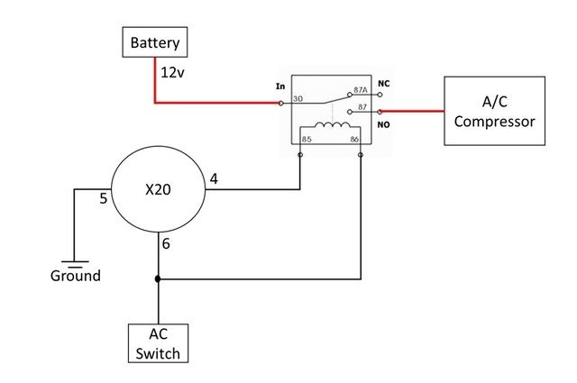
1. For AC switch, I 'tap' the wiring near the fuse box. You can use directly from the AC switch, or find it elsewhere which suit your build. Basically, it should give 12v whenever your press the AC switch button.
2. For the relay, you might need to adjust the relay's pin depends on the relay type.
I've done this in my swap project with DME 413 and Siemens 5wk9.
However, PLEASE DO IT WITH YOUR OWN RISK!
If you are success (like I did), your idle will bump when you start the aircon. And when you suddenly floor the throttle, the aircon will be cut-off for a while (2-3 seconds).
Of course you can improvise the wiring to add pressure switch, another relay to control pin #5 to contact ground only when you press the AC switch, and blablabla...
rgds,
abieLast edited by abie199; 03-29-2015, 11:34 AM.Leave a comment:
-
-
So ideally:
Ground to pin 16 of ECU (BK/Gray)
+12 to 19 of ECU(Vi/Gray)
When you fire the AC switch
This will fire the idle bump.Leave a comment:
-
I made it through an entire summer in new orleans without an idle bump and didnt have any stalling issues. I just dont see that it is that necessary.Leave a comment:
-
would love to know this... it's the last part of the wiring puzzle for meLeave a comment:
-
I haven't checked my AC wiring since my last post, time to bump this up on the todo list.Leave a comment:
-
AC Idle bump
I'm restoring a Tron arcade game at work, is beautiful, like new, thanks for asking. Anyway, it also has a grey wire and a violet wire that used to go to the original power supply that had an R-C circuit that would pulse +5v on-off-on when the game boots and that would reset the ram and allow the game to run. Now that we have a switching power supply installed we no longer have that R-C circuit and the game won't boot. What we have found so far is that putting +5v on violet doesn't boot every time, but putting +5v on grey boots 90% of the time. We're thinking of building a circuit to replicate the proper timing sequence, or just the effect of clearing the ram, but there are other work arounds we will also try.
We'll see how it goes.
I know that has nothing to do with your car, but I have grey and violet wires and weird old technology to troubleshoot too. Good luck!Leave a comment:
-
-
What line are you connecting the AC switch to at the ECU to trip the idle bump?Leave a comment:


Leave a comment: