Announcement

Collapse
No announcement yet.

e30 M3 minor rust repair.

Collapse
This is a sticky topic.
X
X
 
  • Filter
  • Time
  • Show
Clear All
new posts

    This air feed is what keeps the engine breathing when the
    throttles are shut and as it feeds all four cylinders I'm hoping that the vacuum in
    this pipe should be smooth enough for the Map sensor to do it's thing.
    Had this problem with an RB26 engine. All we did though was make a mini plenum i.e. stiff plastic box, that dampened down the pulses.

    Comment


      ^^ thanks for the heads up, much appreciated.

      Comment


        Before we kick off this update it's probably worth mentioning that I've had a very
        polite e-mail informing me that I've somehow managed to make a complete balls up
        of explaining how a VR cranksensor actually works in the last update.
        So, I've taken the time to do some intensive research into the workings of a VR sensor
        and get a better understanding of it, so that I might be able to pass the knowledge on.

        The VR sensor works by................................... nah, still can't figure it out.

        Moving on..............

        With all the main inputs taken care of, the ecu can now get it's arse in gear and
        start to earn it's living. Once it's checked over the incoming sensor info it
        can then decide how much fuel to squirt in and when to fire the spark.

        First up for us is the spark.

        With the standard management system there's quite a few components involved
        in the job of getting the spark created, and then, carrying it down to the sparkplug
        to set off the bang.
        First up, the standard ignition coil......


        The coil is fed a constant 12 volts once the ignition is switched on and
        then the ecu switches the coils earth wire on and off to create a nice fat whack of voltage.
        Once the ecu has trigged the coil the high voltage travels out and into the high tension lead.........


        Which carries it all the way up the the distributor cap, whereupon it enters through the bottom
        port..........


        Once at the distributor cap the voltage travels inside and passes
        over onto the centre of the spinning rotor arm............


        As the rotor arm is bolted onto the end of the camshaft it's spinning around
        with the engine. And once the tip of the rotor arm lines up with one of the
        brass poles on the inside of the distributor cap the voltage takes a leap
        and is off on it's way again.........


        After jumping to the brass pole it's off out to that cylinders HT lead.......


        (picture borrowed from Google)

        And finally after travelling down the HT lead it reaches the sparkplug,
        where upon it completes it's journey by jumping to the earth probe of the sparkplug
        and the resulting spark lights the booom.......


        I know, I know, pure Einstein stuff, but bare with me.
        All of this works perfect on a standard engine, and, even a highly
        modified one if the truth be told.
        So, as you'd expect, I've gone an fu*ked with it.

        What you see below is what's sometimes referred to as a "wasted spark"
        coil........


        As the new Dta ecu now fitted to the car gives me the option to use one
        of these I'm going to run with it.
        Probably worth a few words on how it works before explaining why I've chosen
        to go this route.
        The coil shown above while looking like one chunky fat unit is
        actually two separate coils moulded into one unit.........


        The ecu can either trigger a spark from the red coil or the green coil.
        As you can see in the pic above each half of the coil has two connections
        for HT leads. The leads for cylinder 1 and 4 are connected into the green
        half and cylinders 2 and 3 into the red half......


        When a spark is required in cylinder 1 the ecu fires the green half of the coil
        and the two leads plugged into this half both get the large whack of voltage.
        The result is both the sparkplugs in cylinder 1 and 4 fire at the same time.
        The spark for cylinder 1 arrives and sets off the ignition of the compressed
        fuel and air in this cylinder, while further down the block the spark also
        arrives in cylinder 4. However as this cylinder is just pumping out burnt exhaust
        gases at the moment when the spark goes off it does nothing.

        This is the same process every time a spark is needed. The ecu will trigger
        whichever half of the coil that sends the voltage to the sparkplug that needs it,
        and, it will always travel down the other HT lead connected to this half of the
        coil aswell. The voltage that travels down the other lead will always create a spark
        in a cylinder thats pumping out exhaust gases and as such will be wasted.
        Hence the nick name for this type of ignition system, "wasted spark".

        So, thats how I think it works, as always xworks enterprises can not be held responsible for early
        life termination as a result of this explanation, all contracts are binding, the price of your shares
        can go up as well as down, blah, blah, blah, yada, yada, yada.........

        Next logical question would be, why am I choosing to fu*k with an ignition system that works
        perfectly well.
        And the answer is simple, or to be more accurate, simplify.
        With the wasted spark set up shown above all you have is the coil, three wires running to it
        from the ecu which power it up and trigger coil A or B, and then a few HT leads to carry
        the high voltage down to the spark plugs. And thats it, thats the sub total of our new ignition system.
        With the addition of one simple self contained wasted spark coil we've managed to dump the distributor,
        the distributor cap and the rotor arm, all of which can be a source of frustrating ignition problems as they age.

        And that, in a nutshell, is the reason for going the wasted spark route. No performance advantage, just plain
        old reliability.

        With all that said, it's almost certain now that this new coil will somehow manage to short out and set the car on fire
        just to keep Murphy's Law alive and well.

        More pic's, less bull. Here how it all got nailed together.

        With the distributor deleted this left the small problem of a gaping hole in the end of the cam box.
        Step forward one distributor blanking plate supplied by Massive (link to website earlier in thread)..........


        And bolt it on to cover the hole where the distributor used to be........


        There is one other slight change which can be noticed in the picture above
        and thats the three little studs that used to hold on the distributor and now
        hold on the cover plate. They've been replaced with slightly longer studs.
        The reason being they've another job to do as well.
        Cardboard template............


        transferred to aluminium.........


        weldy, weldy......


        and bolt her up..........


        Comment


          and bingo, we now have somewhere for our new coil to mount........


          If I'm to be honest, this took a bit of smoke between the ears to figure out
          as the coil needed to be in just the right place for one simple reason...........


          I wanted to be able to use the standard HT leads without having to
          get a custom length set made up..........


          Thats not to say the standard leads were a straight forward fit with the new coil,
          obviously there'd be no fu*king fun it things went that simple. A little problem
          had to be taken care of before they sat into place. Each lead was removed from the
          carrier tube............


          And a small section of the insulation rubber on the coil end connector had to
          be removed..........


          with a very sharp knife...........


          Comment


            To say I was a little nervous doing this would be an understatement.
            These leads cost a bloody fortune, and probably the best way of describing
            the tense nature of the moment would be to imagine yourself removing
            one of these from your person........


            with one one these........


            Many cautious hours later..........


            And now with that little bit of insulation removed from each lead all four
            could comfortably fit in place on the coil..........


            bit of rerouteing of the leads back into their tube...........


            and thats the ignition side of things sorted.........


            Next up will be the fuelling.
            Till then...........

            Comment


              oohhhh SHMEXY cant wait for next update. Great work as always
              sigpic

              Comment


                Harley engines used to have wasted sparks, and it was a common mod to go single spark as apparently, burnt gases are not necessarily entirely burned and therefore you could have some more combustion on the way up which would not help.

                Thinking about it now, it sounds a bit far fetched.

                Comment


                  I don't know the percentages, but, if you pop the bonnet on most
                  mass production cars these days you'll see a wasted spark
                  coil setup. Individual coil on plugs (cop) seem to be reserved, for
                  the most part, for high performance models. I've yet to learn what
                  ,if any, performance advantage the coil on plug setup offers.
                  I'd imagine theres some reason for it though, they seldom tend to
                  do things for the craic.

                  Comment


                    Originally posted by xworks View Post
                    I don't know the percentages, but, if you pop the bonnet on most
                    mass production cars these days you'll see a wasted spark
                    coil setup. Individual coil on plugs (cop) seem to be reserved, for
                    the most part, for high performance models. I've yet to learn what
                    ,if any, performance advantage the coil on plug setup offers.
                    I'd imagine theres some reason for it though, they seldom tend to
                    do things for the craic.
                    Not much really besides what was mention before about possible residue in the exhaust stroke. They also allow long charge time extending the life of the coil, apparently. The new BMW S65 has knock sensors build into each COP. The only other advantage is you never need to replace leads.

                    The residure in the Exhaust stroke should not be a problem with a well designed engine. If you have designed your engine right you should have 100% burn at the end of the power stroke.
                    sigpic

                    Comment


                      All cars now days use COP; it's much less expensive than a distributor/rotor/wasted spark system as it requires no spark plug wires ("leads") and needs merely an ECU trigger to fire. Timing is very tightly controlled, often with 4 or 5 individual sparks firing off within the millisecond to ensure complete ignition and combustion. It also simplifies the construction on the engine and means only 1 part is needed (the COP) instead of a myriad of different parts doing different jobs (coil, rotor, distributor, etc)

                      Comment


                        First of all, absolutely love this thread.

                        I'm pretty sure Saab has used COP since '93 (my '93 9000 Aero had them, but I don't know if they did it any earlier). They also used the spark plug as a knock sensor, allowing their high output turbo engines to run on low octane fuel if needed. Turbo pressure was simply dialed back until no knock was happening. Of course, this meant less power, but it also meant you won't wreck an engine because you couldn't find (or didn't purchase) high octane fuel.

                        As Corvallis mentioned, multiple sparks can be produced and timing can be very tightly controlled.

                        ~Peter
                        '89 325iX
                        '04 9-5 Aero Combi

                        Comment


                          Any new updates?

                          Comment


                            ^+1
                            E30 buildy things
                            http://www.r3vlimited.com/board/showthread.php?t=195286

                            Comment


                              Apologies for the lack of updates in here for the last while folks, the
                              finishing post was in sight and it was all steam ahead to avoid another
                              summer lost fu*king about in the garage. Now that theres some more
                              free time again I'll try and finish telling the story.

                              First part of the fuel system overhaul started many, many moon's ago
                              in a galaxy far, far away. The old fuel tank was kaput. She had started to
                              rust at the seams and once the rust gets in here theres not many viable options
                              to repair.
                              So, new tank.......


                              and a fresh "in tank" lift pump to replace the old unit..........


                              The "in-tank" fuel pump shown above has one sole purpose and thats
                              to suck fuel out of the tank and pump it to the main high pressure fuel
                              pump shown below.........


                              Also included in the pic above is the fuel filter below the high pressure pump.
                              I think early cars had the filter mounted along side the high pressure pump like
                              shown above whereas later cars had the filter mounted separately up in the
                              engine bay.
                              As always seems to be the case, just after I'd coughed up the ransom
                              to replace the pair of fuel pumps I came across a forum thread detailing
                              how to junk the 2 pump setup and replace it with a single "in-tank" high
                              pressure pump instead, which works out a damn sight cheaper.

                              Fu*king forums.

                              With the new pumps in place all the associated plumbing was freshened up aswell.
                              Actually, was a little frightening to see the condition some of the old fuel hoses
                              were in. Do yourself a favour, if your driving a twenty year old car and don't
                              know when the fuel hoses were last changed, put it on the top of the
                              "Shit to do" list. Unless your Michael J. Fox and driving a DeLorean
                              then flames don't look so good coming out from underneath a moving car.........


                              So, pumps and hoses in, the fuel can now get from the tank all the way up
                              to the engine bay where upon it fills this little item.......


                              Which is of course the fuel rail. When the engine is up and running the ecu opens
                              the injectors for a preprogrammed amount of time to squirt in just the right amount of
                              fuel thats needed. For this to work then the fuel present in the fuel rail has to be at a constant
                              pressure. For this engine that pressure is 3 bar. The ecu has no way of watching the fuel pressure
                              and will always presume the fuel pressure is 3 bar. If for some reason something went tits up and
                              the fuel pressure went higher than this in the rail, then the ecu still opens the injectors the same
                              length of time and more fuel will get squirted in leading to the engine running rich.
                              Likewise if the pressure dropped in the rail less fuel would be squirted in running the engine lean.

                              So, how the hell do we keep fuel at the right pressure in the fuel rail?
                              Well, it's all done by this little lad bolted on to the end of the fuel rail,
                              surprisingly known as the fuel pressure regulator.........


                              It's not a terribly complicated device and if your not familiar with the workings of one
                              then probably the best way of describing how it works is comparing it to placing your
                              finger over the end of a garden hose. When you block the water coming out of the hose the
                              pressure builds, let your finger off a little and some water squirts out and the pressure
                              drops off in the hose. The regulator shown above does basically the same thing.
                              The fuel pump pumps the fuel up to the fuel rail, fills the rail and try's to flow out the end of the
                              fuel rail where it meets the regulator. Inside the regulator there's a little valve held shut with a
                              spring. Once the fuel pressure builds up enough force to push the spring back the valve opens
                              and lets some fuel return back to the fuel tank. In this regulator the spring is just the
                              right tension to keep the fuel rail pressurised at 3 bar all the time and it's constantly open
                              to some degree returning fuel to the petrol tank.


                              Next up is the injectors.
                              As you may have seen previously during the build theres been a few mods done to the
                              engine to improve it's breathing capability with a view to finding some extra horse power.
                              And as the engine should hopefully now be fit to take in more air we're going to have to
                              mix some more fuel with this to find the extra bhp.
                              Unfortunately the standard injectors weren't going to be up to the task for this engine.
                              As mentioned earlier the Ecu opens and closes the injectors to allow the fuel to be squirted
                              into the engine. As the revs start to rise the amount of time the ecu has available to
                              open and close the injectors to get the fuel in before those inlet valves close and combustion starts
                              is getting smaller and smaller. With the increased amount of air now coming into this engine at high revs
                              the ecu simply hasn't enough time to keep the injectors open long enough to get enough fuel in.
                              So, the solution?
                              Larger injectors.
                              Bellow you can see a picture of the old standard injector and on the right the new
                              larger cc injectors I've bought............


                              Theres an absolute ton of waffle that can be written about selecting which
                              injectors for your engine and I'm not going to go in to the details of how I
                              came to my choice here, cause to be perfectly honest I think I just got
                              pissed off reading about them in the end and picked these.

                              If your in a similar position down the line then some things worth reading up
                              on are:

                              injector resistance - injectors are basically split into two different groups,
                              high resistance and low resistance. The standard M3 injectors are low resistance
                              and most after market ecu's prefer high resistance. Fitting low resistance injectors
                              to an aftermarket ecu that needs high resistance one's can end up melting the ecu.

                              injector cc/min - injectors are usually listed for the amount of fuel they can flow
                              per minute at a given pressure. Usually you'll see them listed in cc/min (cubic centimeters per minute)
                              or lbs/hr (pounds per hour).
                              A standard 195bhp M3 injector flows 236cc of fuel per minute at 3 bar fuel pressure.
                              The new ones I've bought pictured above and below flow 370cc per minute at 3bar.

                              injector body - a quick search around the interweb will show that injectors come in all different shapes
                              and sizes. The standard injectors in an M3 are usually referred to as a Bosch EV1 style.
                              As I wanted the new injectors to be a straight forward fit with the fuel rail and the electrical connector
                              rail I've choose to stick with the EV1 style body.

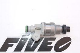
                              More details of the actual injectors I ended up buying can be found here.........
                              #html-body [data-pb-style=IG977QD]{justify-content:flex-start;display:flex;flex-direction:column;background-position:left top;background-size:cover;background-repeat:no-repeat;background-attachment:scroll}Denso high-performance, high resistance, custom fitted fuel injectors.  Custom fit for Asian import 4 and 6 cylinder engines that require a very linear and easy to tune single-pintle fuel injector. Listed Price is for a single injector with pigtail Each set is sold with a complete flow-data chart indicating individual dynamic and static flow rates at 3.0, 3.5, and 4.0 BAR at 15%, 50% and 100% for each injector, along with dead time (latency values) from 8 to 18 volts. Flow-matched to within 1.5%. This is a saturated-type fuel injector.  Denso fuel injector for import super street or racing applications. Fiveo provides individual flow data sheets showing the flow and pressure for each injector. Notice the control numbers etched into the body of each injector (see photos). Fiveomotorsport guarantees injector sets to be matched according to our published specifications. Part number: F87EM380 (pigtail connector included) Injector type: Single pintle, saturated Connector type: Jetronic (EV1) Flow Rates: 36lbs/hr, 380cc/min at 43.5 PSI (3 BAR) Excellent linearity and easy tuning. Resistance: 12.8 Ohms Voltage: 8-15 Volts, Nominal 14.5 Volts Amperage: 1.5 Amps Pressure: Min. 36 PSI (2.5 bar), Max. 101.5 PSI (7 bar) All VITON o-rings/seals included for installation.

                              (just remember, they're high resistance injectors and unsuitable for the standard ecu).

                              One last vital modification to the injectors before they can be fitted was to paint em red.
                              This mod alone will add up 40 horse power and improve fuel economy,
                              remember where you heard it first...........


                              Now that everything was in place the next stage could begin, wiring things up
                              while holding a fire extinguisher.
                              Will try and have it up by the end of the week.

                              Till then.......

                              Comment


                                great update. Love the red injectors, little details... so perfect.
                                E30 buildy things
                                http://www.r3vlimited.com/board/showthread.php?t=195286

                                Comment

                                Working...
                                X