-
I think that you should be able to do this in C. ASM is probably easier, but C should be doable since it sounds like you know what you are doing. You can either use an interrupt from the timer used for the PWM DC checks (assumed in the example below), or with a really fast main loop that checks whatever PWM/CCP status flags indicate where in the output period you are. You would want to change the register holding the DC (which some timer is compared against) close to the beginning of the output-active part of the period so that the timer will then get compared against the new value during that same cycle. So, you need to be updating the PWM DC register at the same rate as the PWM frequency.
Example using some guessed numbers:
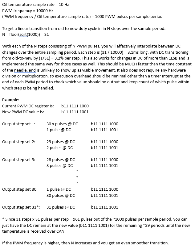
If you wanted to get even fancier, you could spread out the new-DC transition pulses over the 31-pulse step (space them out inside the step, rather than having all of the new pulses accumulate at the end). This would eat a lot more instruction cycles, though, and probably not confer any practical benefit since the gauge needle is pretty slow by comparison.Last edited by bmwman91; 11-21-2018, 11:01 AM.Leave a comment:
-
-
-
The AVR micro I am using is doing a decent amount. Reading from a CANbus, controlling 4 7seg LED displays over i2c and reading sensor data from a ADC over i2c, monitoring the light circuit for at night dimming, and data logging. I guess I will find out if adding this will slow everything downLeave a comment:
-
You could switch to a microcontroller with higher PWM resolution. Microchip dsPIC's are cheap, easy to work with and can easily provide 16b PWM resolution. Otherwise, you can try a PWM dithering scheme if you want to avoid jumps, although it sounds like you are not expecting to ever really have the oil temperature that high. Dithering would mean alternating between the new and old duty cycles rapidly, and linearly changing from 0% new duty cycle to 100% new duty cycle. If your PWM frequency is in the kHz, it would be plenty fast to make it appear smooth on the slow gauge. It's a good amount of additional code, but if this is the only thing that your microcontroller is doing, it should be pretty easy.
Your method seems like a perfectly good way of driving the gauge; it is simple and does not seem to pose any risks to anything.Leave a comment:
-
Its case (b) The gauge is non-linear. I am not so concerned about jumps at the end of the range that oil temp shouldn't actually be hitting. I am more concerned about the set-up and chacking that this is a viable way to drive the gauge long term and if there is a better way.Last edited by BeirBrennerE30; 11-19-2018, 08:21 AM.Leave a comment:
-
Just to be crystal clear, which LSb is the root cause of the sensitivity?
a) CAN temperature value changes one LSb, which maps to a jump of many counts of the PWM duty cycle for high temperatures
b) A change of one LSb of the PWM duty cycle, at high temperatures, makes the gauge jump
Case (a) seems like the more likely culprit. Also, what is the PWM frequency?
If it is case (a), then your only good option is interpolation between PWM duty cycles for the current and previous CAN values, maybe even requiring a moving-average of more than just the last 2 values. If case (b), then you would need to do something similar to the solution for (a), but implemented as a dithering function to interleave the previous and new LSb value fast enough to not show up in the needle.Last edited by bmwman91; 11-17-2018, 10:50 PM.Leave a comment:
-
-
IIRC it was called out as such in my old Chilton's guide which I can't find. Searching around the web, it seems to be a common arrangement on older BMW's, including the E30. One of the two "prongs" in the sender contains a magnet, the other the reed switch, and when one of the vanes on the diff sender wheel passes between, it interrupts the magnetic flux and opens the switch.
/HijackLeave a comment:
-
So at the high temperature end, due to the non-linear transfer function, a one LSb change in the oil temperature value leads to a large jump in the PWM duty cycle / needle position? If so, there are a couple of fairly easy solutions since the needle is a relatively slow device (compared to the 100ms sampling period of the input).
What type of microcontroller are you using?Leave a comment:
-
Sure. SO I built a gauge for the center vent like an Alpina gauge. Some of the info for it I am pulling from the s54 CAN bus (intake temp). I have access to the everything being sent on the CAN bus including oil temp. Oil temp is broadcast every 100ms in 8bits on 0x720. the 8 bits, bin->dec then subtract 48, corresponds to degrees C which the reading the ECU is using for oil temp. So if the ECU sends 0b11001000 = 0xC8 = 200 = 152degC.
I am running an e30 M3 gauge cluster that has the oil temp gauge built in. I know to get this gauge to function I just need to hook up the e30 M3 temp sender which is a thermister essentially. It seems wasteful to have 2 temp senders: one for the MSS54 ecu and data log, and another just for the gauge. Ideally I thought it would be more efficient to have the module that was receiving CAN and logging everything to control the cluster oil temp gauge so the temp displayed is the oil temp that the ECU is actually using. Sanity check on what the ECU is seeing as well as monitor oil temp
The microcontroller that I am using for the gauge has a PMW out for 10bit resolution. I have successfully used the PWM to drive a transistor on the signal line for the e30 M3 oil temp gauge and control it. So my next step was going to be to make a table to compare the oil temp I am receiving to what the PWM out should be.
The jump between pwm steps at the high end of the gauge, >210degF, gets a little choppy on the gauge. Its nonlinear from PWM steps to what is displayed on the gauge. But I figure that isnt that big of an issue since temps getting much above that mean I have bigger cooling issues.
For this thread I am asking for a sanity check if anyone has feedback or knows of a better way to do this. Or in the alternative tell me I am crazy and just to hook up the e30 M3 sender.Last edited by BeirBrennerE30; 11-09-2018, 08:51 AM.Leave a comment:
-
I'm a little confused what you're asking at this point. Is your issue driving the gauge? Or? Can we start over? :)Leave a comment:
-
What is the PWM frequency?
How clean are the oil temp values given by the CAN bus? As in, do you need to do some digital averaging on the received values, or are they pretty well low-pass filtered for noise before the MSS54 sends them? I'd assume that the ADC input stages in the ECU have at least a little filtering on them, but who knows.Leave a comment:

Leave a comment: