Announcement

Collapse
No announcement yet.

Documentary - Motronic 1.7 DIY Reverse Engineering

Collapse
X
 
  • Filter
  • Time
  • Show
Clear All
new posts

  • vwnut8392
    replied
    nice to see the BMW community doing some reversing of the old motronics! you guys make me wish i still had my E30 so i could join in the fun! ive done a lot of work on PRJ's audi M2.3.2 stuff like the high speed logging, the speed density conversion etc. i'd have to disassemble an E30 BIN but if all my findings from looking at all the other 8051 based motronics falls true than you can simply study what was done in the audi M2.3.2 binary files and relate it almost directly to the E30 files. not everything is going to line up but you have to realize that all the old 8051 based chips regardless of who the car manufacturer was created with bosch's assembler and they didnt exactly go out of their way to make radical changes in the software as per the manufacturer they was making it for, they just put things in different places and worded things differently per say.

    when i say worded things differently like in some BIN files i found that the analog inputs are accessed with
    Code:
    mov     DPTR, #BE06
    than the raw value is moved the ADC converter. The other way i have seen is
    Code:
    mov     ADCON1, #6
    . the both achieve the same thing essentially but they are just done in different ways. The other thing i found is sometimes they have indirect constant and table addressing while other times its a direct address to a table or constant via DPTR.


    For making a high speed logging output that should not be too difficult. the max baud rate of the siemens based 8051 processor is 187500baud. All you have to do is find the original factory data output in the code and where it starts. than from that point jump out to some custom code that will essentially grab whatever variables from RAM and push them out through the processors serial port over the K-line. In the case of M2.3.2 high speed logging it was told to send 0xAA and 0xBB before the RAM variables, sending these 2 bits is a good way to tell software like tuner pro RT that the ECU is sending data and to watch for these 2 bits to start the live reading.

    Here is an example of test logging code i made for M2.3.2 motor chip for audi 200 20v turbo. fyi the audi motronic has 2 ECU's in one, one to control the timing/fueling and the other is boost control/knock control. the code from the boost processor/chip would be useless in the BMW application.

    Code:
    code:00005B30
    code:00005B30          ; =============== S U B R O U T I N E =======================================
    code:00005B30
    code:00005B30
    code:00005B30          code_5B30:                              ; CODE XREF: code_3C4E↑p
    code:00005B30 20 24 15                 jb      RAM_24.4, code_5B48 ; Jump if Bit is set
    code:00005B33 E5 3A                    mov     A, RAM_3A       ; Move (Op1 <- Op2)
    code:00005B35 70 0B                    jnz     code_5B42       ; Jump if Acc is not zero
    code:00005B37 90 BE 00                 mov     DPTR, #0xBE00   ; Move (Op1 <- Op2)
    code:00005B3A 12 13 5D                 lcall   code_135D       ; Long Subroutine Call
    code:00005B3D F4                       cpl     A               ; Complement Operand
    code:00005B3E 60 02                    jz      code_5B42       ; Jump if Acc is zero
    code:00005B40 D2 24                    setb    RAM_24.4        ; Set Direct Bit
    code:00005B42
    code:00005B42          code_5B42:                              ; CODE XREF: code_5B30+5↑j
    code:00005B42                                                  ; code_5B30+E↑j ...
    code:00005B42 12 34 08                 lcall   code_3408       ; Long Subroutine Call
    code:00005B45 02 3C 51                 ljmp    code_3C51       ; Long Jump
    code:00005B48          ; ---------------------------------------------------------------------------
    code:00005B48
    code:00005B48          code_5B48:                              ; CODE XREF: code_5B30↑j
    code:00005B48 E5 3A                    mov     A, RAM_3A       ; Move (Op1 <- Op2)
    code:00005B4A B4 0A 00                 cjne    A, #0xA, code_5B4D ; Compare Operands and JNE
    code:00005B4D
    code:00005B4D          code_5B4D:                              ; CODE XREF: code_5B30+1A↑j
    code:00005B4D 40 F3                    jc      code_5B42       ; Jump if Carry is set
    code:00005B4F 75 87 80                 mov     PCON, #0x80     ; Power Control Register
    code:00005B52 75 98 E8                 mov     SCON, #0xE8     ; Serial Channel Control Reg.
    code:00005B55 75 A0 00                 mov     P2, #0          ; Port 2
    code:00005B58 30 AC 01                 jnb     IEN0.4, code_5B5C ; Interrupt Enable Register 0
    code:00005B5B 22                       ret                     ; Return from subroutine
    code:00005B5C          ; ---------------------------------------------------------------------------
    code:00005B5C
    code:00005B5C          code_5B5C:                              ; CODE XREF: code_5B30+28↑j
    code:00005B5C 78 AF                    mov     R0, #0xAF       ; Move (Op1 <- Op2)
    code:00005B5E 08                       inc     R0              ; Increment Operand
    code:00005B5F 74 FD                    mov     A, #0xFD        ; Move (Op1 <- Op2)
    code:00005B61 F2                       movx    @R0, A          ; Move from/to external RAM
    code:00005B62 08                       inc     R0              ; Increment Operand
    code:00005B63 E5 3A                    mov     A, RAM_3A       ; Move (Op1 <- Op2)
    code:00005B65 F2                       movx    @R0, A          ; Move from/to external RAM
    code:00005B66 08                       inc     R0              ; Increment Operand
    code:00005B67 E5 3F                    mov     A, RAM_3F       ; Move (Op1 <- Op2)
    code:00005B69 F2                       movx    @R0, A          ; Move from/to external RAM
    code:00005B6A 08                       inc     R0              ; Increment Operand
    code:00005B6B E5 36                    mov     A, RAM_36       ; Move (Op1 <- Op2)
    code:00005B6D F2                       movx    @R0, A          ; Move from/to external RAM
    code:00005B6E 08                       inc     R0              ; Increment Operand
    code:00005B6F E5 37                    mov     A, RAM_37       ; Move (Op1 <- Op2)
    code:00005B71 F2                       movx    @R0, A          ; Move from/to external RAM
    code:00005B72 08                       inc     R0              ; Increment Operand
    code:00005B73 E5 38                    mov     A, RAM_38       ; Move (Op1 <- Op2)
    code:00005B75 F2                       movx    @R0, A          ; Move from/to external RAM
    code:00005B76 08                       inc     R0              ; Increment Operand
    code:00005B77 90 BE 00                 mov     DPTR, #0xBE00   ; Move (Op1 <- Op2)
    code:00005B7A 12 13 5D                 lcall   code_135D       ; Long Subroutine Call
    code:00005B7D F2                       movx    @R0, A          ; Move from/to external RAM
    code:00005B7E 08                       inc     R0              ; Increment Operand
    code:00005B7F 79 5F                    mov     R1, #0x5F ; '_' ; Move (Op1 <- Op2)
    code:00005B81 E3                       movx    A, @R1          ; Move from/to external RAM
    code:00005B82 F2                       movx    @R0, A          ; Move from/to external RAM
    code:00005B83 08                       inc     R0              ; Increment Operand
    code:00005B84 E5 54                    mov     A, RAM_54       ; Move (Op1 <- Op2)
    code:00005B86 F2                       movx    @R0, A          ; Move from/to external RAM
    code:00005B87 08                       inc     R0              ; Increment Operand
    code:00005B88 E5 5E                    mov     A, RAM_5E       ; Move (Op1 <- Op2)
    code:00005B8A F2                       movx    @R0, A          ; Move from/to external RAM
    code:00005B8B 08                       inc     R0              ; Increment Operand
    code:00005B8C E5 5F                    mov     A, RAM_5F       ; Move (Op1 <- Op2)
    code:00005B8E F2                       movx    @R0, A          ; Move from/to external RAM
    code:00005B8F 08                       inc     R0              ; Increment Operand
    code:00005B90 E5 6F                    mov     A, RAM_6F       ; Move (Op1 <- Op2)
    code:00005B92 F2                       movx    @R0, A          ; Move from/to external RAM
    code:00005B93 08                       inc     R0              ; Increment Operand
    code:00005B94 75 A0 01                 mov     P2, #1          ; Port 2
    code:00005B97 79 70                    mov     R1, #0x70 ; 'p' ; Move (Op1 <- Op2)
    code:00005B99 E3                       movx    A, @R1          ; Move from/to external RAM
    code:00005B9A 75 A0 00                 mov     P2, #0          ; Port 2
    code:00005B9D F2                       movx    @R0, A          ; Move from/to external RAM
    code:00005B9E 08                       inc     R0              ; Increment Operand
    code:00005B9F 12 5B C5                 lcall   code_5BC5       ; Long Subroutine Call
    code:00005BA2 F2                       movx    @R0, A          ; Move from/to external RAM
    code:00005BA3 08                       inc     R0              ; Increment Operand
    code:00005BA4 79 20                    mov     R1, #0x20 ; ' ' ; Move (Op1 <- Op2)
    code:00005BA6 E7                       mov     A, @R1          ; Move (Op1 <- Op2)
    code:00005BA7 F2                       movx    @R0, A          ; Move from/to external RAM
    code:00005BA8 08                       inc     R0              ; Increment Operand
    code:00005BA9 90 63 60                 mov     DPTR, #0x6360   ; Move (Op1 <- Op2)
    code:00005BAC E4                       clr     A               ; Clear Operand (0)
    code:00005BAD 93                       movc    A, @A+DPTR      ; Move code byte relative to second op to Acc
    code:00005BAE F2                       movx    @R0, A          ; Move from/to external RAM
    code:00005BAF 08                       inc     R0              ; Increment Operand
    code:00005BB0 E5 5A                    mov     A, RAM_5A       ; Move (Op1 <- Op2)
    code:00005BB2 F2                       movx    @R0, A          ; Move from/to external RAM
    code:00005BB3 08                       inc     R0              ; Increment Operand
    code:00005BB4 E5 5B                    mov     A, RAM_5B       ; Move (Op1 <- Op2)
    code:00005BB6 F2                       movx    @R0, A          ; Move from/to external RAM
    code:00005BB7 E8                       mov     A, R0           ; Move (Op1 <- Op2)
    code:00005BB8 C3                       clr     C               ; Clear Operand (0)
    code:00005BB9 94 AF                    subb    A, #0xAF        ; Subtract Second Operand from Acc with Borrow
    code:00005BBB 78 AF                    mov     R0, #0xAF       ; Move (Op1 <- Op2)
    code:00005BBD F2                       movx    @R0, A          ; Move from/to external RAM
    code:00005BBE D2 AC                    setb    IEN0.4          ; Interrupt Enable Register 0
    code:00005BC0 75 99 FE                 mov     SBUF, #0xFE     ; Serial Channel Buffer Reg.
    code:00005BC3 22                       ret                     ; Return from subroutine
    code:00005BC3          ; End of function code_5B30
    code:00005BC3
    code:00005BC3          ; ---------------------------------------------------------------------------
    code:00005BC4 FF                       .byte 0xFF
    code:00005BC5
    code:00005BC5          ; =============== S U B R O U T I N E =======================================
    code:00005BC5
    code:00005BC5
    code:00005BC5          code_5BC5:                              ; CODE XREF: code_5B30+6F↑p
    code:00005BC5 90 BE 06                 mov     DPTR, #0xBE06   ; Move (Op1 <- Op2)
    code:00005BC8 E0                       movx    A, @DPTR        ; Move from/to external RAM
    code:00005BC9 22                       ret                     ; Return from subroutine
    code:00005BC9          ; End of function code_5BC5
    code:00005BC9
    code:00005BC9          ; ---------------------------------------------------------------------------
    code:00005BCA FF                       .byte 0xFF
    code:00005BCB FF                       .byte 0xFF
    code:00005BCC FF                       .byte 0xFF
    code:00005BCD FF                       .byte 0xFF
    code:00005BCE FF                       .byte 0xFF
    code:00005BCF FF                       .byte 0xFF
    code:00005BD0
    code:00005BD0          ; =============== S U B R O U T I N E =======================================
    code:00005BD0
    code:00005BD0
    code:00005BD0          RI_TI_0_0:                              ; CODE XREF: RI_TI_0↑j
    code:00005BD0
    code:00005BD0          ; FUNCTION CHUNK AT code:00004185 SIZE 0000000C BYTES
    code:00005BD0
    code:00005BD0 20 24 07                 jb      RAM_24.4, code_5BDA ; Jump if Bit is set
    code:00005BD3 02 41 85                 ljmp    code_4185       ; Long Jump
    code:00005BD6          ; ---------------------------------------------------------------------------
    code:00005BD6 20 99 01                 jb      SCON.1, code_5BDA ; Serial Channel Control Reg.
    code:00005BD9 32                       reti                    ; Return from Interrupt
    code:00005BDA          ; ---------------------------------------------------------------------------
    code:00005BDA
    code:00005BDA          code_5BDA:                              ; CODE XREF: RI_TI_0_0↑j
    code:00005BDA                                                  ; RI_TI_0_0+6↑j
    code:00005BDA C0 83                    push    DPH             ; Data Pointer, High Byte
    code:00005BDC C0 82                    push    DPL             ; Data Pointer, Low Byte
    code:00005BDE C0 E0                    push    ACC             ; Accumulator
    code:00005BE0 C2 99                    clr     SCON.1          ; Serial Channel Control Reg.
    code:00005BE2 90 00 AF                 mov     DPTR, #0xAF     ; Move (Op1 <- Op2)
    code:00005BE5 E0                       movx    A, @DPTR        ; Move from/to external RAM
    code:00005BE6 70 09                    jnz     code_5BF1       ; Jump if Acc is not zero
    code:00005BE8 C2 AC                    clr     IEN0.4          ; Interrupt Enable Register 0
    code:00005BEA D0 E0                    pop     ACC             ; Accumulator
    code:00005BEC D0 82                    pop     DPL             ; Data Pointer, Low Byte
    code:00005BEE D0 83                    pop     DPH             ; Data Pointer, High Byte
    code:00005BF0 32                       reti                    ; Return from Interrupt
    code:00005BF1          ; ---------------------------------------------------------------------------
    code:00005BF1
    code:00005BF1          code_5BF1:                              ; CODE XREF: RI_TI_0_0+16↑j
    code:00005BF1 C0 D0                    push    PSW             ; Program Status Word Register
    code:00005BF3 14                       dec     A               ; Decrement Operand
    code:00005BF4 F0                       movx    @DPTR, A        ; Move from/to external RAM
    code:00005BF5 24 B0                    add     A, #0xB0        ; Add Second Operand to Acc
    code:00005BF7 F5 82                    mov     DPL, A          ; Data Pointer, Low Byte
    code:00005BF9 E0                       movx    A, @DPTR        ; Move from/to external RAM
    code:00005BFA F5 99                    mov     SBUF, A         ; Serial Channel Buffer Reg.
    code:00005BFC D0 D0                    pop     PSW             ; Program Status Word Register
    code:00005BFE D0 E0                    pop     ACC             ; Accumulator
    code:00005C00 D0 82                    pop     DPL             ; Data Pointer, Low Byte
    code:00005C02 D0 83                    pop     DPH             ; Data Pointer, High Byte
    code:00005C04 32                       reti                    ; Return from Interrupt
    code:00005C04          ; End of function RI_TI_0_0
    code:00005C04
    code:00005C04          ; ---------------------------------------------------------------------------
    A true speed density conversion would be possible with an external MAP sensor wired into the MAF's signal wire but i feel it would also require some ECU hardware modifications to get a proper signal to the processor. Than there would have to be software modifications as well to compensate for the MAP sensor. also if i remember correctly only automatic E30's had a TPS sensor where as the manual ones had only closed and WOT? if thats true than everyone would need to convert to the auto TPS sensor because a sort of alpha-N blending is necessary with speed density in motronic for sharp throttle movements. basically theres a bit to the speed density conversion but i wont get into that right now.
    Last edited by vwnut8392; 12-29-2018, 01:47 PM.

    Leave a comment:


  • red318is
    replied
    Wow! This thread is way above my head, but I think it's fascinating. Nice work!

    Leave a comment:


  • biela
    replied
    Hello

    Great job here!

    I have loaded TotalCombinedROM.bin in IDA, following Rasp indications.

    Trying to understand the code but, can anybody post a simple function explained? Like calls to 2D or 3D tables.

    Thanks

    Leave a comment:


  • MarkD
    replied
    Originally posted by Rasp View Post
    If you want play with Motronic datalogging RAM variables by K2 protocol with standart baudrate 9600, you can use KWP71Diag tool https://mega.nz/#!jU8A1ZYA!ajEXKoQy_...hmoGrmZh3r0T54
    with predefined config to M1.7-M1.7.3


    This program will work with simple VAG COM KKL 409.1 adapter, but only with FTDI chip!

    Virtual COM port must be configured:

    Rasp, are there definitions for other Motronic ECU's such as M1.3? Also, is the source code for the program available? I'd like to pot it into a microcontroller, and seeing the source would be a big help.

    Leave a comment:


  • bmwman91
    replied
    OK, I have a new thread specific to M1.7.3 efforts. This one has a lot of good info on M1.7.x and it is very long already. So, work will continue here:


    Thanks!

    Leave a comment:


  • bmwman91
    replied
    I tried doing local heating with a heater like that on the M1.7, and that is how I ended up with bubbles in the layers. The thermal expansion of the board in small local areas was too much since the surrounding areas were cooler, and the stresses from this separated layers. So I think that a small toasting oven should work better since the whole board will heat at the same rate. I have been wanting to build a reflow soldering oven for a while anyway, and a solid state relay with an Arduino and K-type thermocouple should be about all I need to make a regular toaster oven into a PID-controlled soldering oven. But, I will do that later, all I need for now is to heat the PCB to ~200°C.

    Leave a comment:


  • Rasp
    replied
    Originally posted by bmwman91
    Also...I know it does not matter to functionality, but leaving old unused code in there is super annoying lol.
    Looks like after M1.7 software developed negligently, because a lot of debug code is include in release M1.7.2 and M1.7.3.


    Originally posted by bmwman91
    I set this one to the 535...but that should not make a difference (since all code is external and in the correct order already)?
    Yes, its one family of cpu and in software decompilation there is no difference.

    Originally posted by bmwman91
    But basically, the summary from your nice first post is that as long as you get the data segments marked as data/undefined, all of the code that actually matters will be identified and traced properly by IDA on the first-pass?
    Yes, except jmp @A+DPTR code blocks.

    Originally posted by bmwman91
    I am going to find a super cheap toaster oven on Craigslist (local-version of eBay)
    Maybe, better to use building dryer?

    Leave a comment:


  • bmwman91
    replied
    Ah, right. OK yeah if it is initializing data memory then the code makes sense.

    Also...I know it does not matter to functionality, but leaving old unused code in there is super annoying lol.

    I set this one to the 535...but that should not make a difference (since all code is external and in the correct order already)?


    But basically, the summary from your nice first post is that as long as you get the data segments marked as data/undefined, all of the code that actually matters will be identified and traced properly by IDA on the first-pass?

    Also, the ECUs that I ordered on eBay have shipped and I am hoping to get them next week. It should be easy enough to assign component references based on my existing M1.7 schematic and the M1.7.2/990 unit which I have as a reference. With all of the stuff I learned taking the first one apart, I think that I can do this one faster and better than the previous one. I am going to find a super cheap toaster oven on Craigslist (local-version of eBay) and basically use that to get the whole PCBA to reflow temperature slowly and evenly so that I can just "wipe" components off and pull them out of their holes. This should eliminate the issues I had with the soldering iron tip digging into the board, ripping the hole plating and bubbling apart the FR4 layers.
    Last edited by bmwman91; 01-29-2018, 11:01 AM.

    Leave a comment:


  • Rasp
    replied
    Originally posted by bmwman91 View Post
    I loaded the 64K BIN into IDA. It seems that there is a lot of clean-up to do with code/data mix-ups and such. It is a little hard to tell with some of the red no-Xref code sections whether those are actually orphan code or data constants, and the addresses seem to be in "not data" areas in many cases. Admittedly, I am not great with IDA and I am not anywhere near familiar with the way that old Motronic firmware was structured. Still, it's interesting.
    In M1.7.3 is a lot of orphan code because its based on M1.7.2, but programmers dont clean previous code, just put above nop and lcall to new code.

    Originally posted by bmwman91
    There are 3 places where the disassembly has MOV instructions from RESERVED memory addresses. 232Bh, 66EBh and 6ACEh. The functions are IEX3_0 (first one) and RESET_0 (last two), so it seems like this is not orphan code?
    See my first message, its stack initalization.

    Originally posted by bmwman91
    Do you change any of the extra options/setting when initially loading the project and selecting the processor?
    See my first message, you need select 515 CPU and do not touch everything else.

    Leave a comment:


  • bmwman91
    replied
    I loaded the 64K BIN into IDA. It seems that there is a lot of clean-up to do with code/data mix-ups and such. It is a little hard to tell with some of the red no-Xref code sections whether those are actually orphan code or data constants, and the addresses seem to be in "not data" areas in many cases. Admittedly, I am not great with IDA and I am not anywhere near familiar with the way that old Motronic firmware was structured. Still, it's interesting.

    There are 3 places where the disassembly has MOV instructions from RESERVED memory addresses. 232Bh, 66EBh and 6ACEh. The functions are IEX3_0 (first one) and RESET_0 (last two), so it seems like this is not orphan code?

    Do you change any of the extra options/setting when initially loading the project and selecting the processor? I have played with those a little, but I am not familiar enough with what they do to know which ones might be beneficial.

    Leave a comment:


  • Rasp
    replied
    Originally posted by bmwman91
    Are all of the M1.7.3 units made with no component references printed on the board?
    Yes, I'm never saw M1.7.3 with component references printed on board.

    Originally posted by bmwman91
    Firmware from any M1.7.2 can be used on any hardware version and still work properly, correct?
    Seems like all M1 BMW firmwares looks pretty same (and yes all M1.7.2 firmwares is can be changed vise versa), excluding the processing of missing equipment of course. It can be some differences in processing IO ports (you noticed that pinout of DME is little different, but it can be, because of different board design), so real difference will be clear only after comparing the schematics.

    Originally posted by bmwman91
    The 6-cylinder BMW's have had 90% of the attention (for obvious reasons), but I am into the 4 cylinder cars, and a little crazy, so it's time to open this stuff up for the community.
    Undeservedly forgotten, although this is one of the best 4-cylinder engines :) by the way M1.7.3 can be used for 6 cylinders with two banks of injection and 3 paired ignithion coils, or leave distributor.

    Leave a comment:


  • bmwman91
    replied
    True, at that point maybe they finally had digital schematics and did not need big hand-drawn papers anymore. Are all of the M1.7.3 units made with no component references printed on the board? It's OK if they are, but it will make reverse engineering them a little bit harder since I will have to guess / invent reference numbers.

    The differences in the PCB are in a few places. M1.7 and M1.7.2/990 have jumpers tying different ground networks together (metal enclosure, ignition drivers, everything else) and M1.7.2/282 has just joins the copper layers entirely. In the case of the older Motronics, this would actually make for separate ground terminals on the 88 pin connector, and I assume that they did this to leave themselves the option of using multiple ground points if ignition currents caused signal issues. But, since by the mid-90's they must have realized that this would not be an issue, they just tied everything together in copper. That is just one difference, there are others. The images I posted are less than half the size of my originals, and I also spent a little time holding the boards to look for differences.

    Ultimately, it is not important since it sounds like all of the functional bits are effectively the same. Firmware from any M1.7.2 can be used on any hardware version and still work properly, correct? I know that there is not much use to documenting this, but since there has been so little information posted on these units for so long, I feel like now is the time to shine light on it once and for all. The 6-cylinder BMW's have had 90% of the attention (for obvious reasons), but I am into the 4 cylinder cars, and a little crazy, so it's time to open this stuff up for the community.

    Leave a comment:


  • Rasp
    replied
    Good comparsion!

    The M5.2 unit I have is also this way, so I guess that around the mid-90's Bosch decided to make things even harder to reverse engineer
    Perhaps there it was no longer necessary to publish somewhere schematic (maybe partially) for repair and no need make reference designators.
    It's unlikely that a monopolist like Bosch would have to be afraid of competitors (in mid-90's there only Siemens could be considered as same, today, however, nothing has changed)
    especially reverse engineers, which even after 30 years is not so much.
    Although some communities of open systems would do well to simply "take and copy" proven solutions of those years...

    Also, there are PCB layout differences between 990 and 282, with differences in components and the copper layers, although the layers do look ~90% the same.
    I think is just for saving money, with a layman's eye (me :) ) PCB looks like same (software too, without any serious changes).

    Leave a comment:


  • bmwman91
    replied
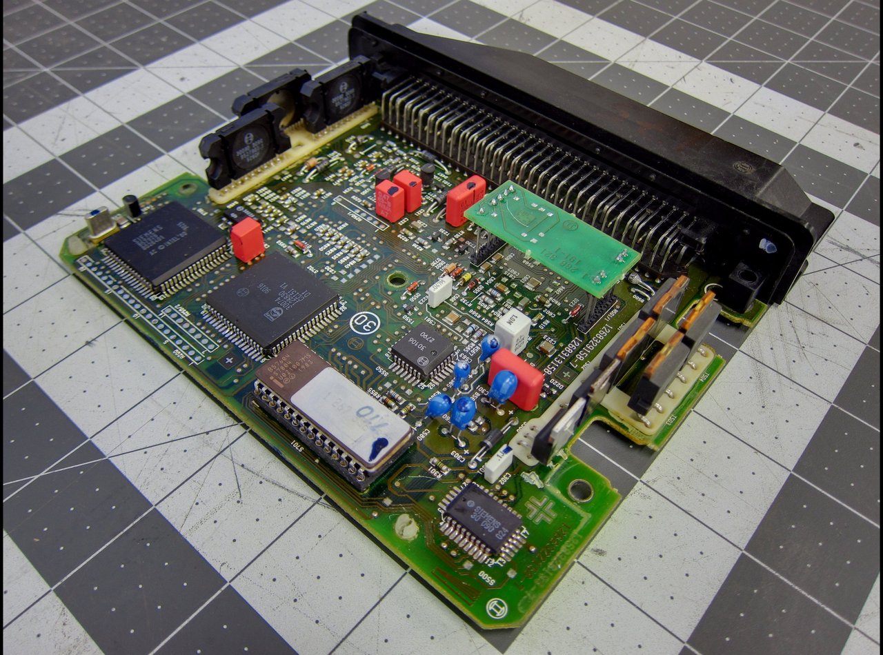
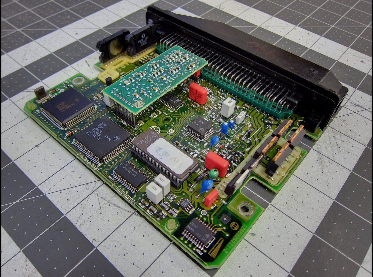
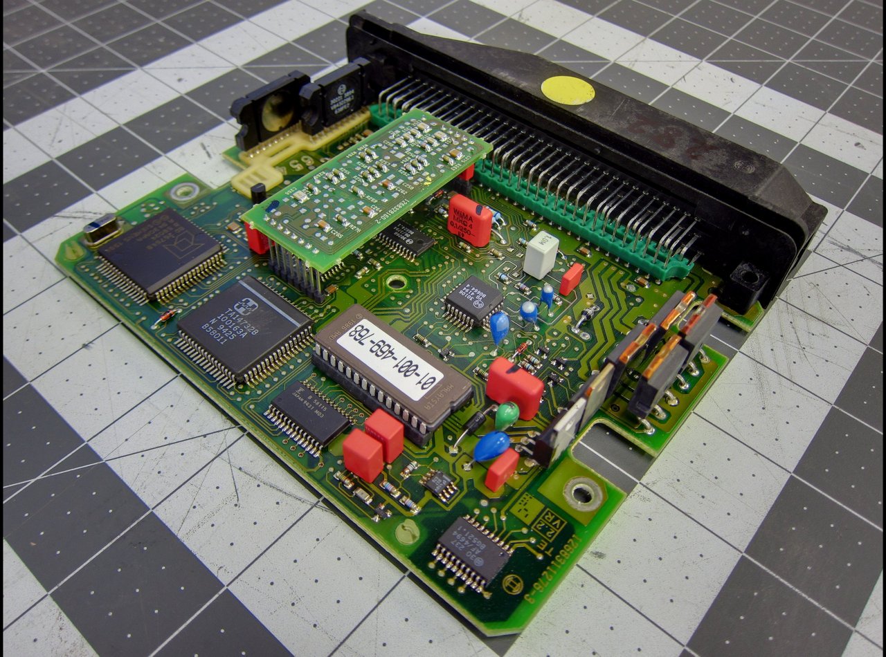
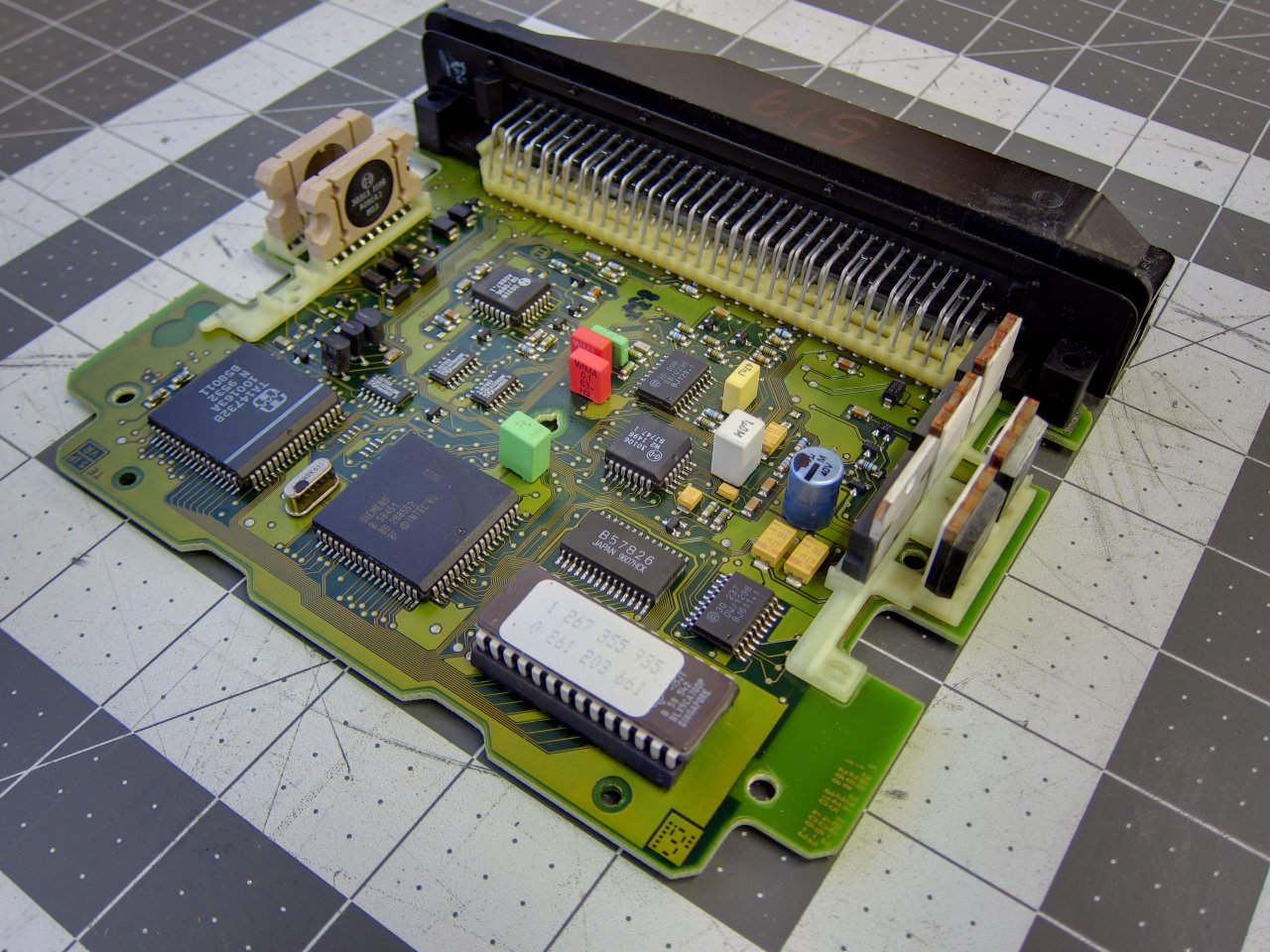
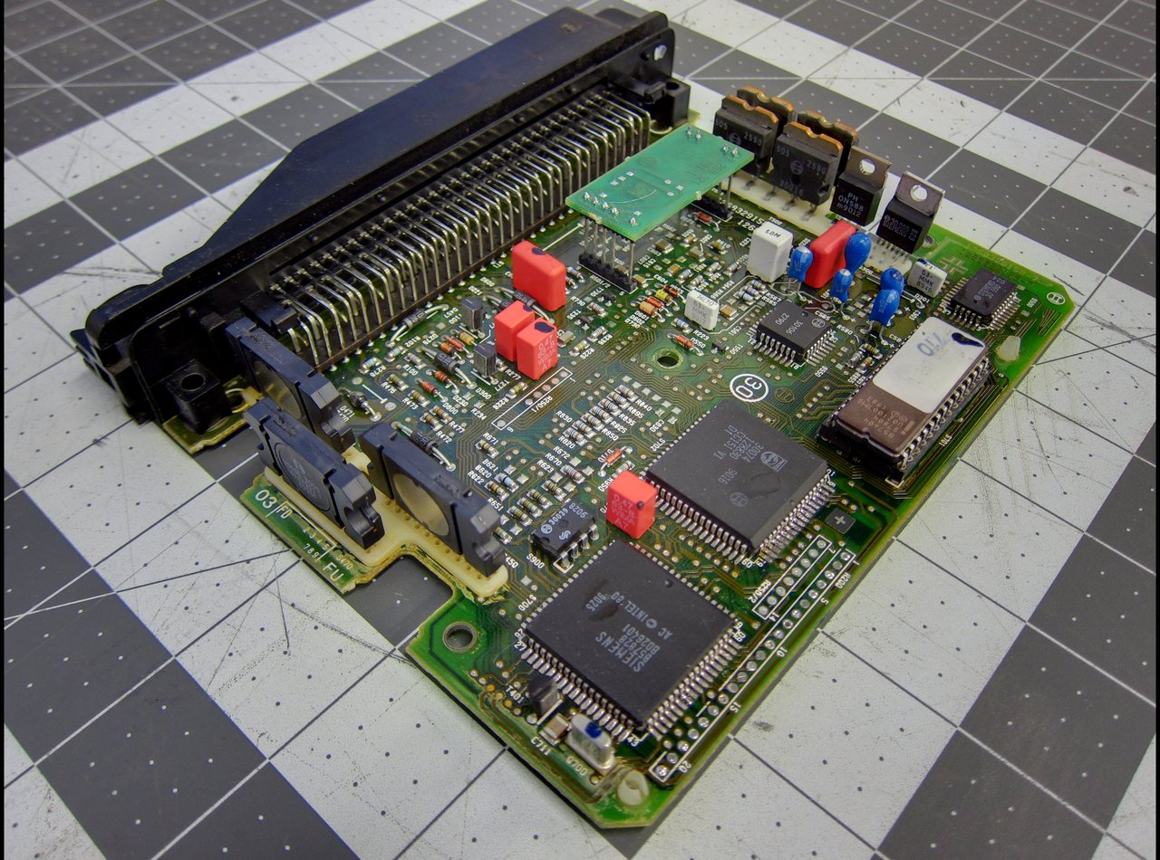
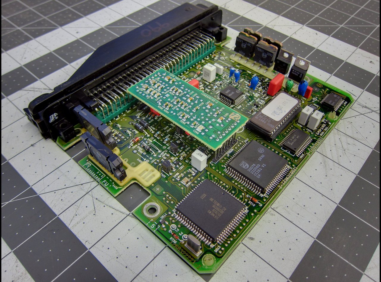
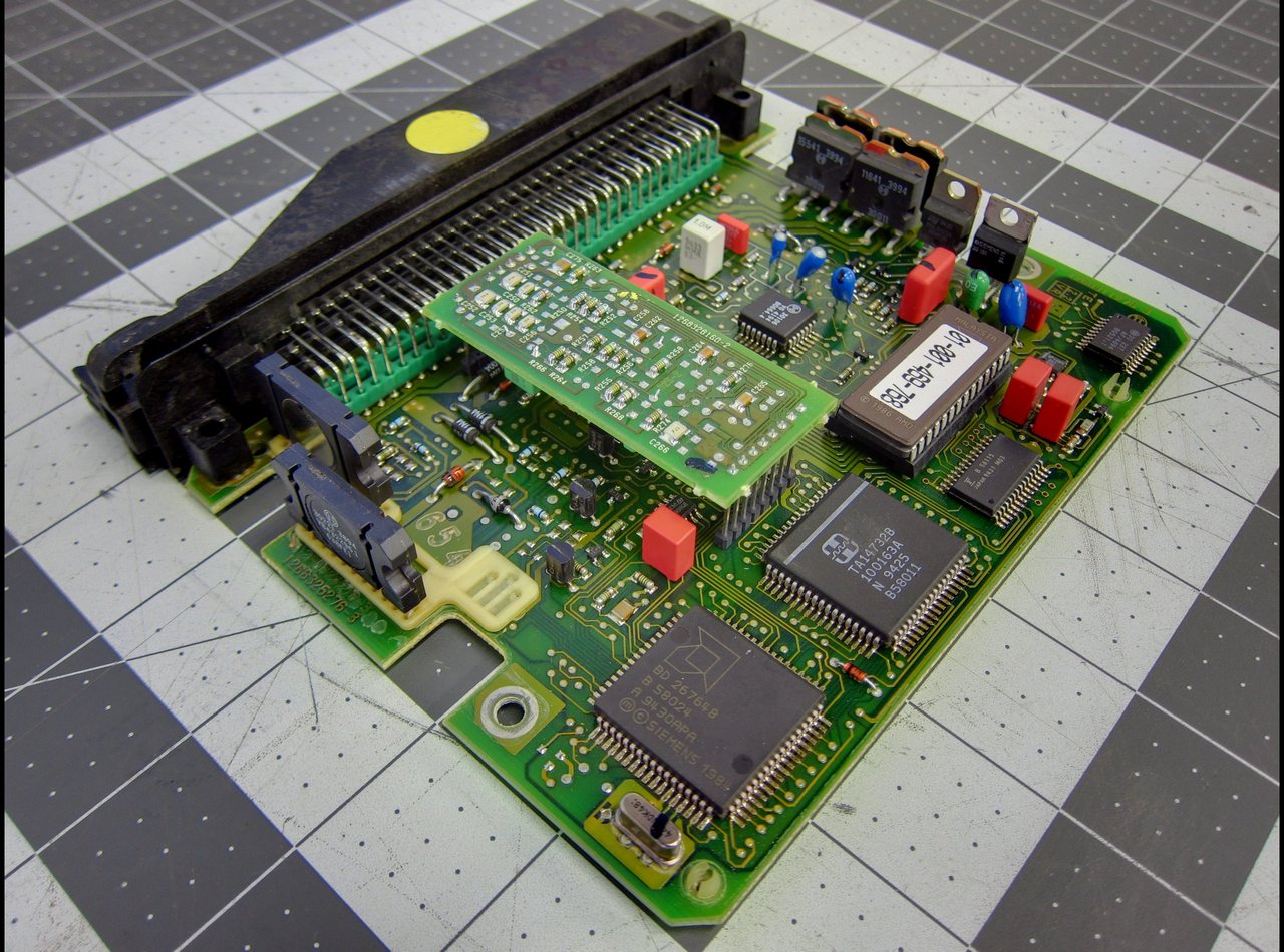
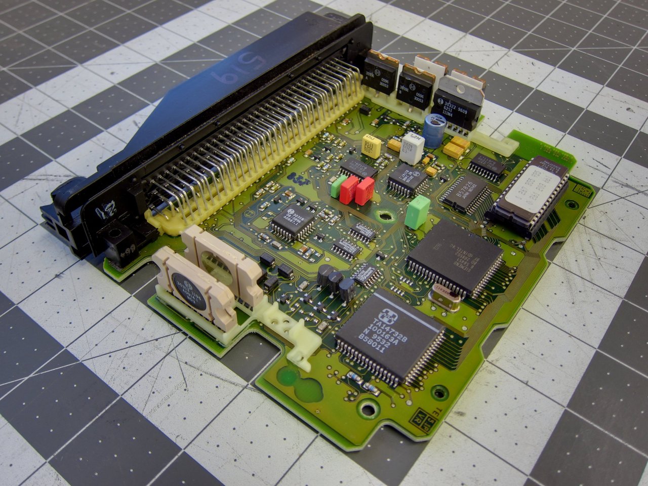
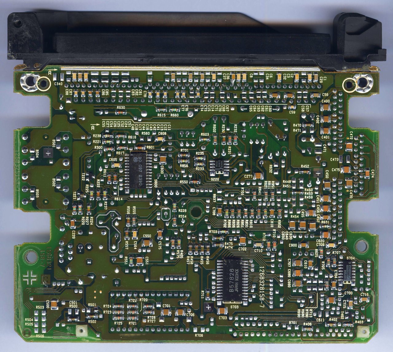
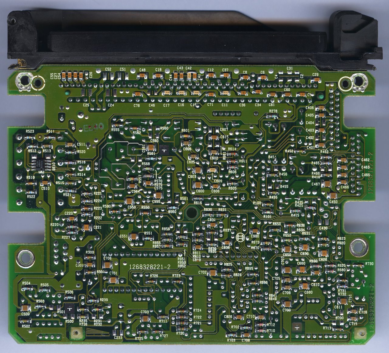
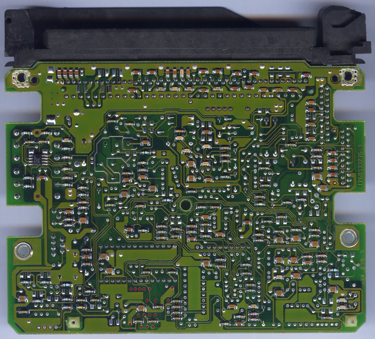
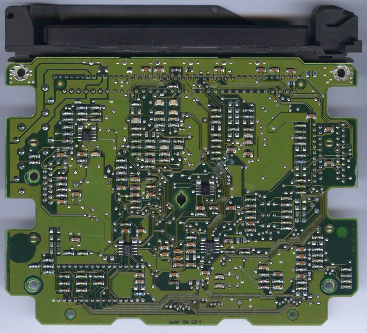
    A couple of the eBay M1.7.2 units showed up today, so I took a little time to get photos of these just for purposes of documenting rough hardware differences. The 990 and 282 ECUs are not identical, with the most notable (to me) change being that the 282 unit eliminates all silkscreen reference designators. The M5.2 unit I have is also this way, so I guess that around the mid-90's Bosch decided to make things even harder to reverse engineer. If someone can think of a better reason why, I am all ears. Also, there are PCB layout differences between 990 and 282, with differences in components and the copper layers, although the layers do look ~90% the same.

    When I receive the M1.7.2 0261203277 unit, I will add the same photos/views to this post.

    The units next to one another. Bosch decided not to use thermal gap pads on the mid-current drivers in the 282 ECU, which is interesting to me (left to right: 175, 990, 282, 661)


    Top view 1
    M1.7 - 0261200175


    M1.7.2 - 0261200990


    M1.7.2 - 0261203282


    M1.7.3 - 0261203661


    Top view 2
    M1.7 - 0261200175


    M1.7.2 - 0261200990


    M1.7.2 - 0261203282


    M1.7.3 - 0261203661


    Bottom view
    M1.7 - 0261200175


    M1.7.2 - 0261200990


    M1.7.2 - 0261203282


    M1.7.3 - 0261203661
    Last edited by bmwman91; 02-07-2018, 04:22 PM.

    Leave a comment:


  • bmwman91
    replied
    I don't think I'd call his statement "ragging" necessarily, just a very blunt statement about the current state of things. I'm on the MSExtra forums a lot, and a huge number of users have chronic "not running super nice" issues. Naturally some of that is because the people who are running well aren't posting looking for assistance; they are out driving. MS absolutely has a place in the engine management world and it is impressive all on it's own considering that it is open source.

    Also agreed that many people who lack the discipline and budget to do custom management right are also likely to go for MS without fully thinking it through since it looks like the "cheapest way to get more power" when in fact an off-the-shelf chip from a reputable tuner is the "real" answer in these cases. Still, respect to anyone who can even follow through enough to get a car to start on a stand alone system.

    BUT, let's get this back on topic. This rabbit hole is waaaaay too easy to go down and end up with everyone fuming mad! No more mention of MS or other systems unless it pertains directly to this RE effort (please?).

    Leave a comment:

Working...
X