
I also used the same scraper. I specified 84mm stroke when order.
When test fit the scraper, it was not even close. Had to grind off good amount of materials everywhere on the oil pump side and bent the fingers on the other side.
M52 crank still quite different than M20 cranks.
-
Small update:
I needed an indicator to get the motor timed so I picked a cheap one up today after work and got the motor timed this evening...
I put all the front bits put on that are required for the timing...
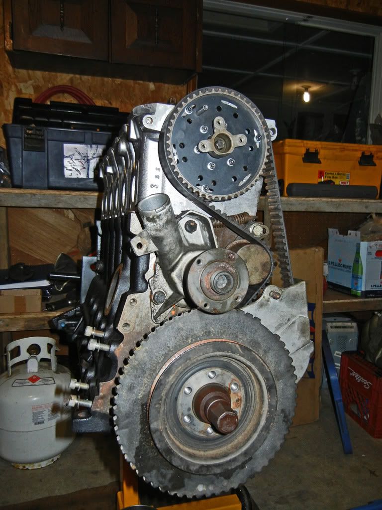
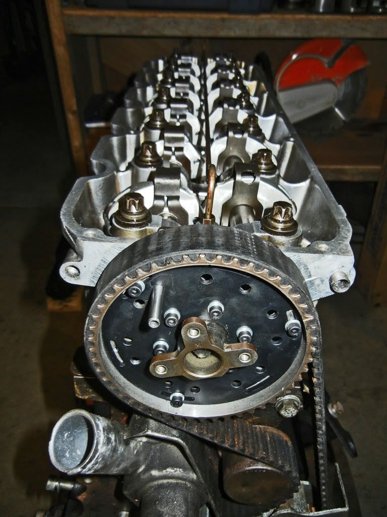
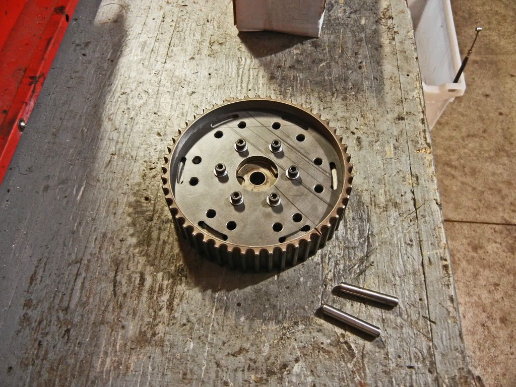
A shot of the DIY adjustable cam gear (still missing some hardware on the outer ring)...
Instead of buying a fancy degree wheel, I printed a degree scale I found online and glued it to a heavy piece of cardboard. Couple that with a piece of wire attached to the block and a dial indicator and we're good to go!...
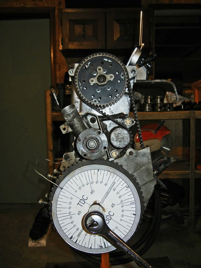
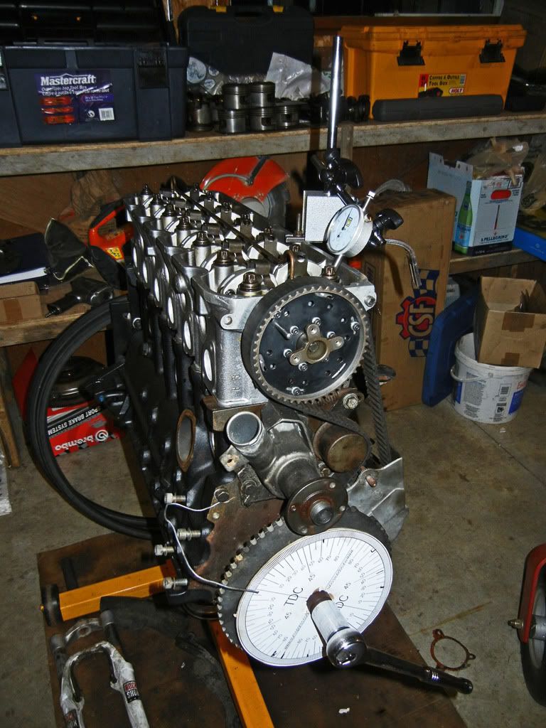
Set the indicator up on the valve spring retainer and make sure that it's parallel to the valve stem...
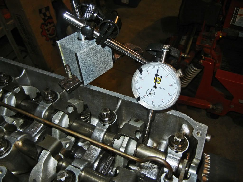
To time the cam I did the following:
- With the motor at TDC (lining up the mark on the timing cover with the O|T mark on the toothed wheel) set the wire indicator on the degree wheel to line up with the TDC mark on the degree wheel
- Rotate the motor clockwise while keeping an eye on the dial indicator. As the valve opens the needle on the indicator will turn counter-clockwise, when you reach max lift the needle will stop. At this point zero the dial on the indicator.
- Continue rotating the motor clockwise and stop when the dial is reading 0.020" past max lift. Write down the degree that the wire indicator is pointing to.
- Continue rotating the motor clockwise, as you approach max lift stop 0.020" before max lift. Write down the degree that the wire indicator is pointing to.
- Add the first number to the second number and divide it by two to get the degree value for your peak timing.
When I first checked the timing I measured it to be 112 degrees which is 2 degrees retarded. I expected the timing to be retarded because of the 0.5mm the block was shaved plus the head getting shaved as well. So since every degree the crank turns the cam gear turns 0.5 degrees I advanced the cam gear by 1 degree using my dowel pin adjustment method. Then I checked the timing again using the method described and it was on 110 degrees as it is supposed to be.
After that I checked valve to piston clearance. In order to do that I turned the cam to max lift. Then I used a wood chisel (with some tape on it to prevent damaging any parts) and the rocker arm as a pivot to lift the rocker until the valve contacted the piston...
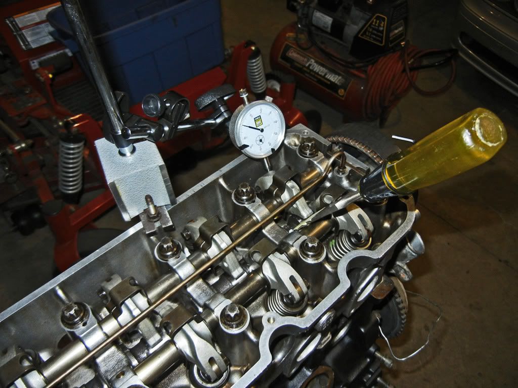
Keeping an eye on the indicator I measured approximated 0.090" (2.28mm) clearance, I also had my valve lash set to zero so in reality I'll have an extra 0.25mm so overall approximately 2.5mm clearance which is adequate.
So now the next step is checking main and rod bearing clearances.
To be continued...Last edited by Bullet Ride; 05-17-2012, 05:58 AM.Leave a comment:
-
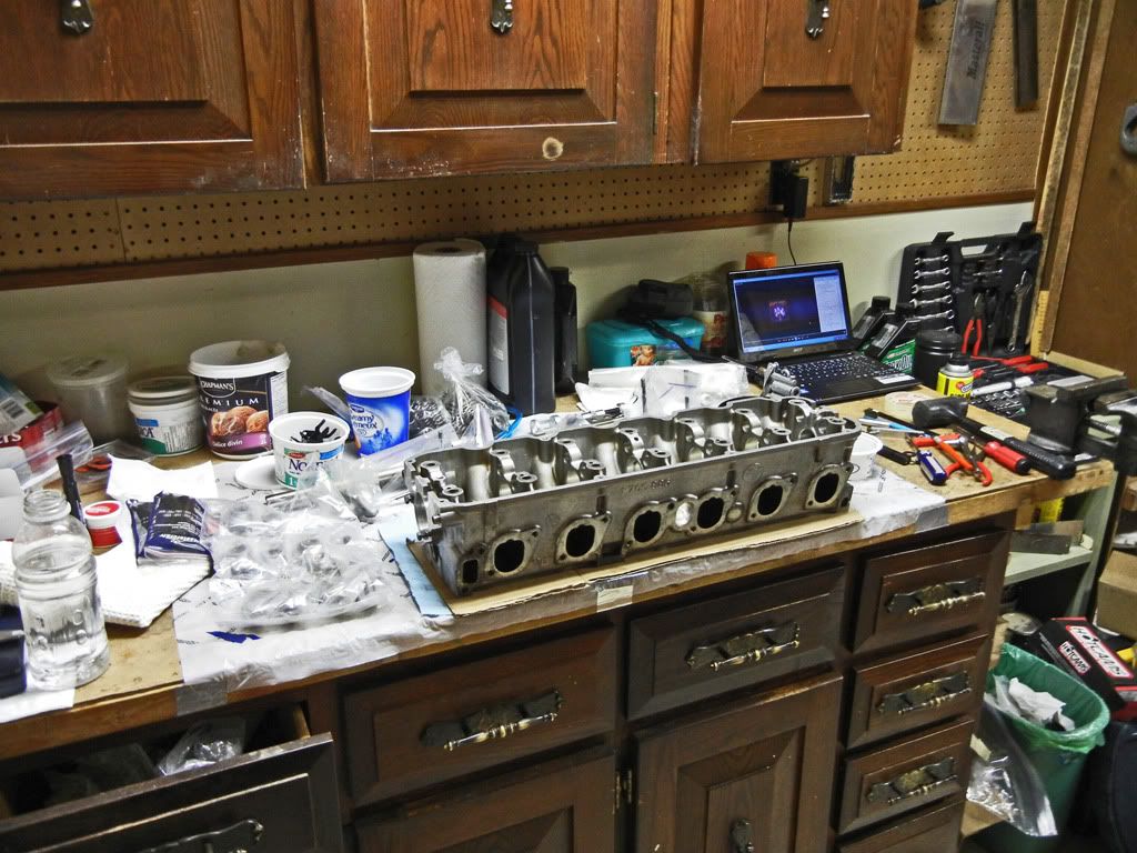
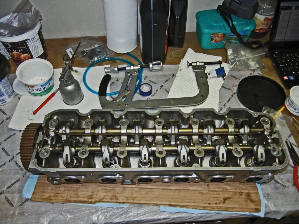
So I spent the afternoon yesterday assembling the head:
Here is the workroom in the basement with parts scattered across the bench along with some of the mess left over from my brother who had just finished rebuilding his dirt bike motor...
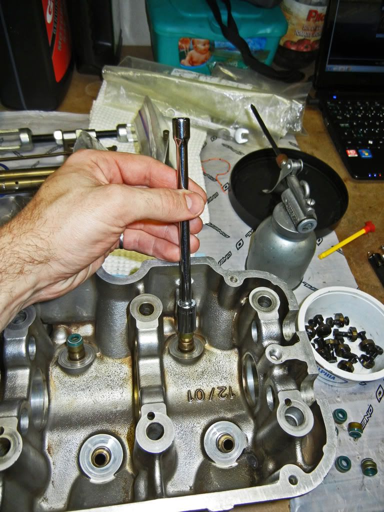
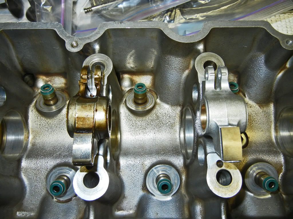
First order of business (after giving everything a final wash and blow off with the compressor) was the valve stem seals. This is probably common knowledge, but I found that an 11mm socket with a long extension made it extremely simple to install the valve seals. The socket will hold onto the seal, even when you turn it upside down, and exert force evenly around the outer edge...
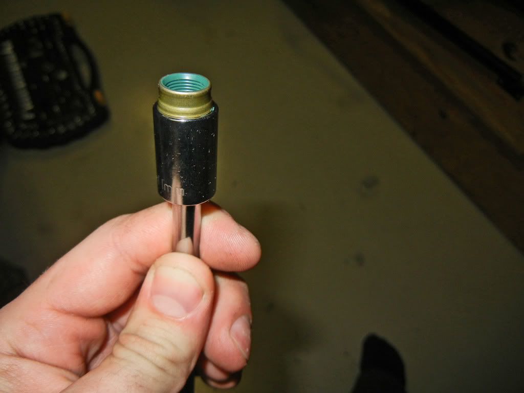
The long extension gives you a bit more room to push, and they push on pretty easily...
Once all the valve seals were installed the springs had to be installed. This part of the assembly actually went a lot smoother than I had anticipated once I figured out a good way to do it. The tricky part is installing the keepers and having them stay in place as you decompress the valve springs. My method which seemed to work well was as follows. Once I had the spring compressed I'd put a drop of oil on the keeper grooves of the valve stem. Then I'd put a drop of oil on the grooves of each keeper. Using a pair of needle nose pliers I'd place the keeper on the bottom side of the valve stem. Now if you have enough oil there, the surface tension should be strong enough to hold it in place. Then I'd rotate the keeper I just installed to the top side of the valve stem. Then using the pliers again I'd install the second keeper. Once both keepers were installed I'd rotate them so that the split was vertical just so that gravity wouldn't be pulling on one more than the other.
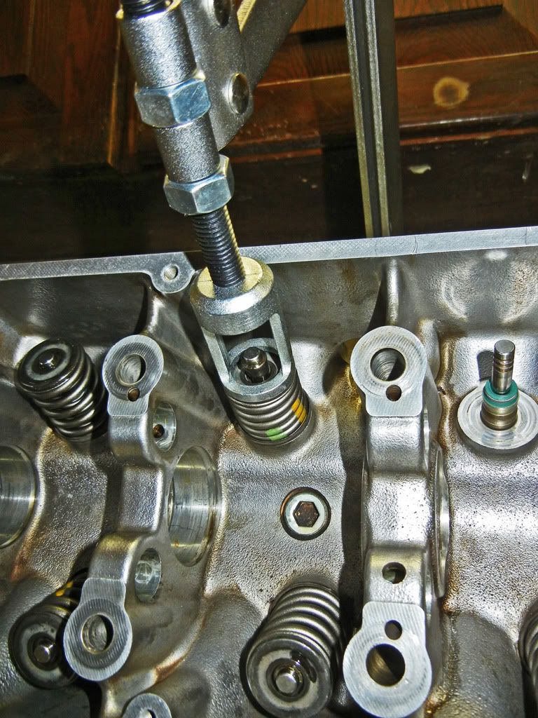
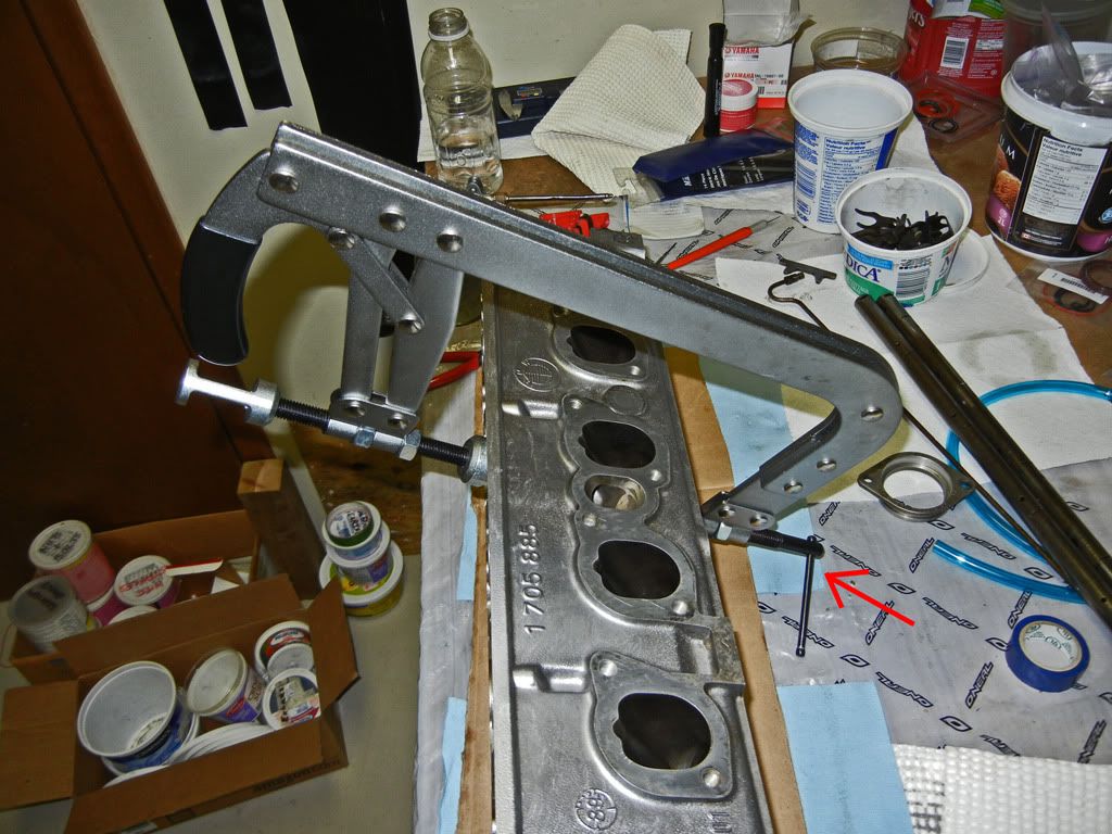
Then rather than releasing the cam lock on the spring compressor I'd decompress the spring by loosening the adjustable pad that's clamping against the valve head (red arrow). This allowed me to ensure that the keepers seated properly in the retainer before releasing the cam lock. I felt that this was a better method than just outright releasing the cam lock and hoping the keepers don't go shooting across the room.
So after not too long the springs were installed...
Then it was time to install the cam and rockers. As I mentioned back in the original post I'm using the IE HD rockers. Here is a comparison between OEM and the HD for those of you who aren't familiar with them...
As you can see where the adjustable eccentric is has been beefed up substantially...
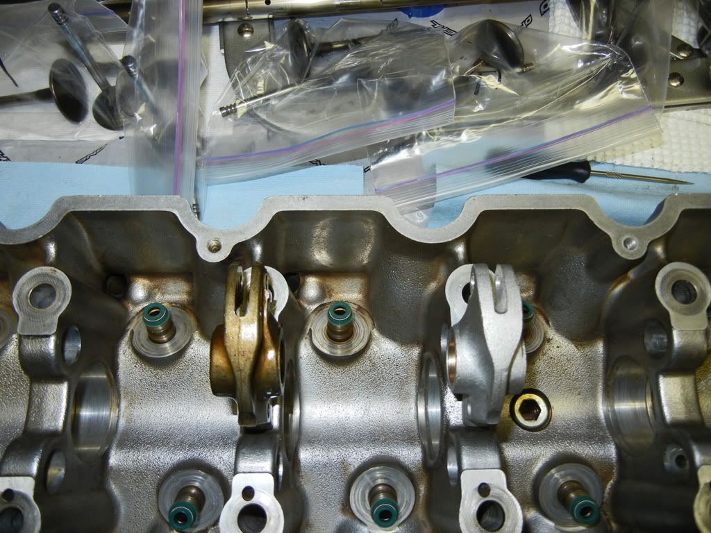
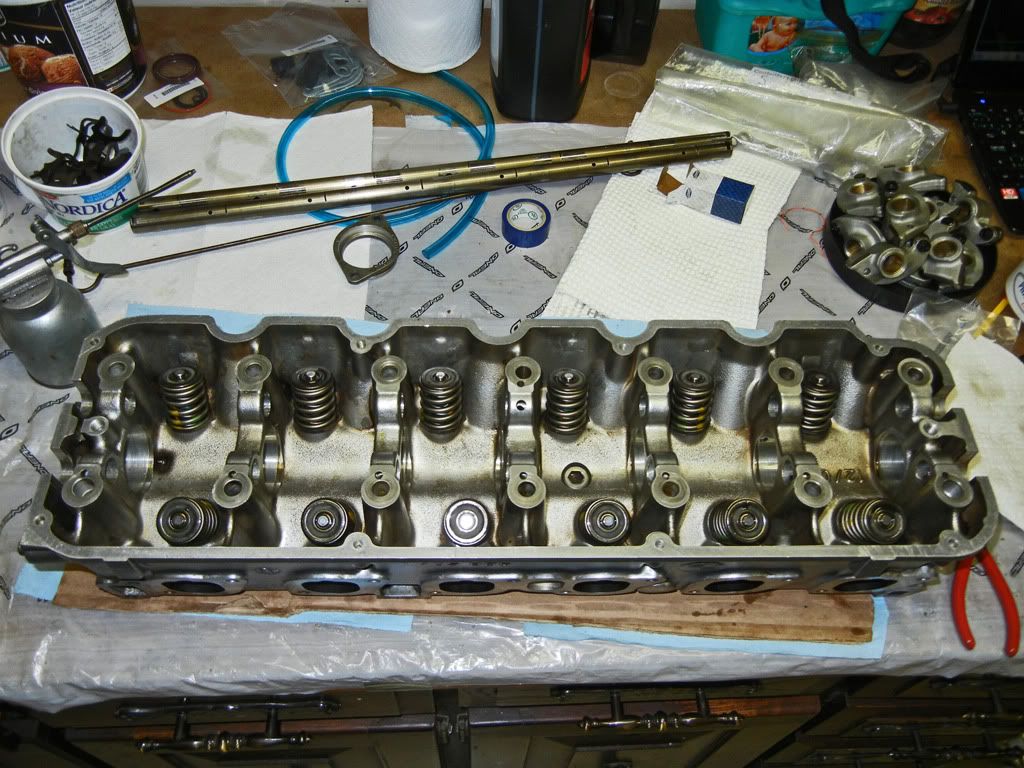
A few more minutes gone by and voilà! My first assembled head....
I spent today giving the old M20 it's last valve adjustment before it get's pulled so it's sounding nice and tight for auto-x next weekend. I also fiddled around with the turbo heap as it will be going on the road within a week!Leave a comment:
-
A couple months ago Treadzone.com was having a blow out on the 205/50R15 size because spec Miata changed over to Hoosier tires this year.Originally posted by acolella76 View Post
.... I got them for $380 shipped :pimp:Leave a comment:
-
Did you get those R888's on eBay for $420?
lulz just realized how many questions i've been asking in this thread. Keep up the good work! I love those tires, they head up instantly. I've been using them for track and autocross duty, and if i had the money i would use them for summer as well.Last edited by acolella76; 04-27-2012, 07:07 PM.Leave a comment:
-
Update time:
Much to my excitement I came home from work today to find a big ol' pile of parts in the garage...
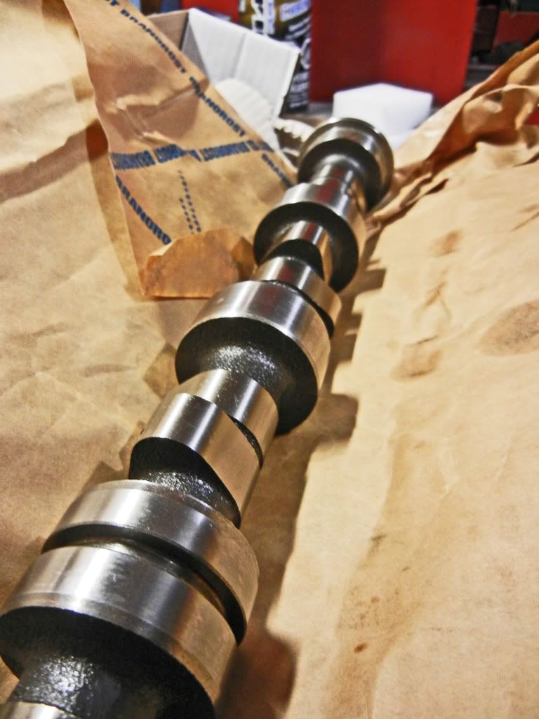
This was sitting on the work bench...
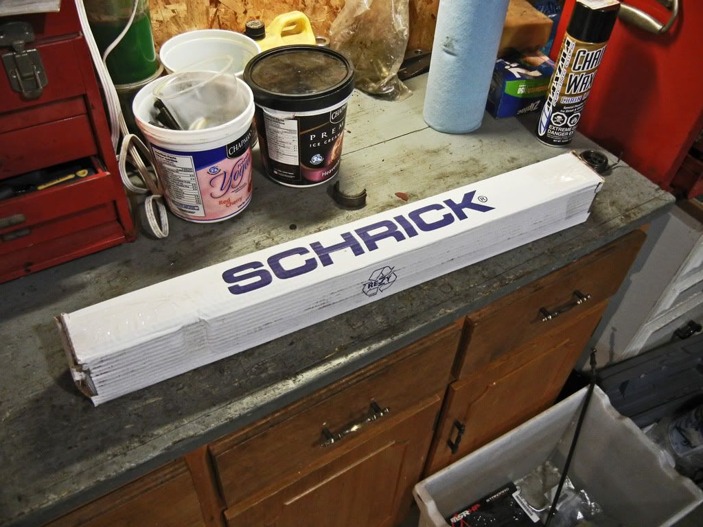
Ask an oriental man to say slick and it'll sound like....
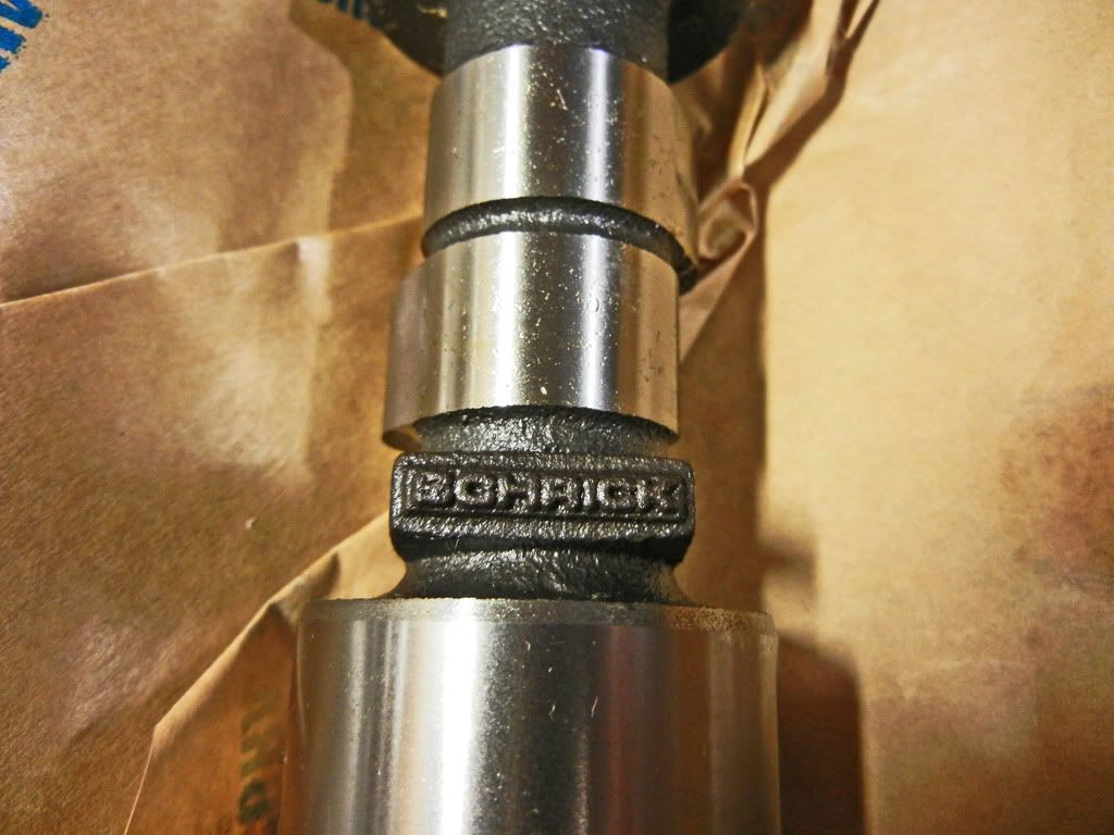
That's a Schrick looking cam...
(p.s. I've got plenty of oriental friends so I feel like I can make that joke lol)
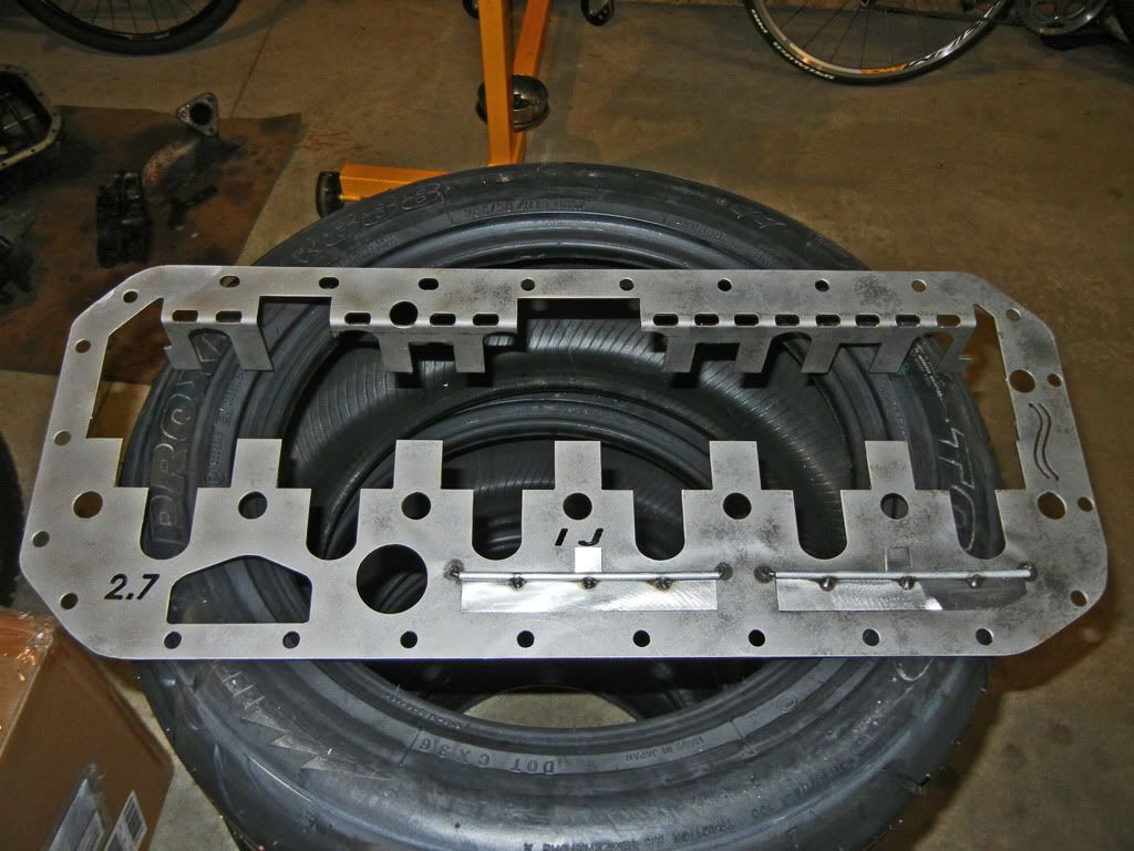
Next up is the #becauseracecar part. I ordered the 2.7 scraper because it's stroke is close to the 2.8 crank. I'll need to adjust the clearances a bit so it won't rub
And the rest of the internals, seals, hardware, etc...
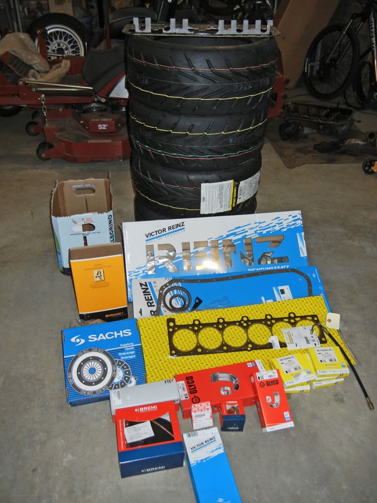
And yes you saw correctly, all those bits were sitting in front of a stack of new Toyo R888s which I got a wicked deal on...
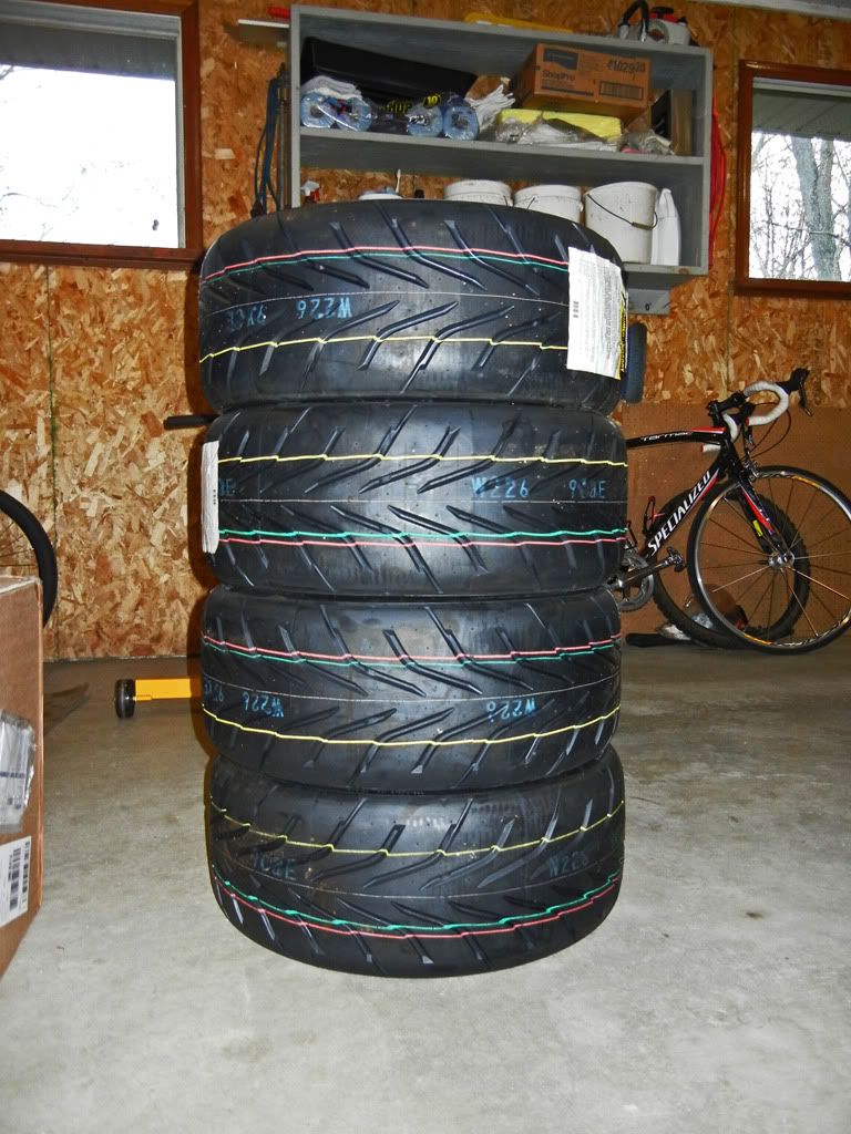
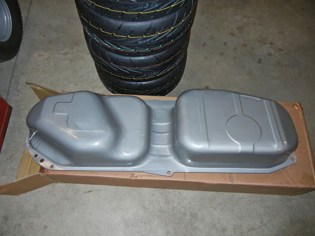
And not directly related to the engine build, but still important...
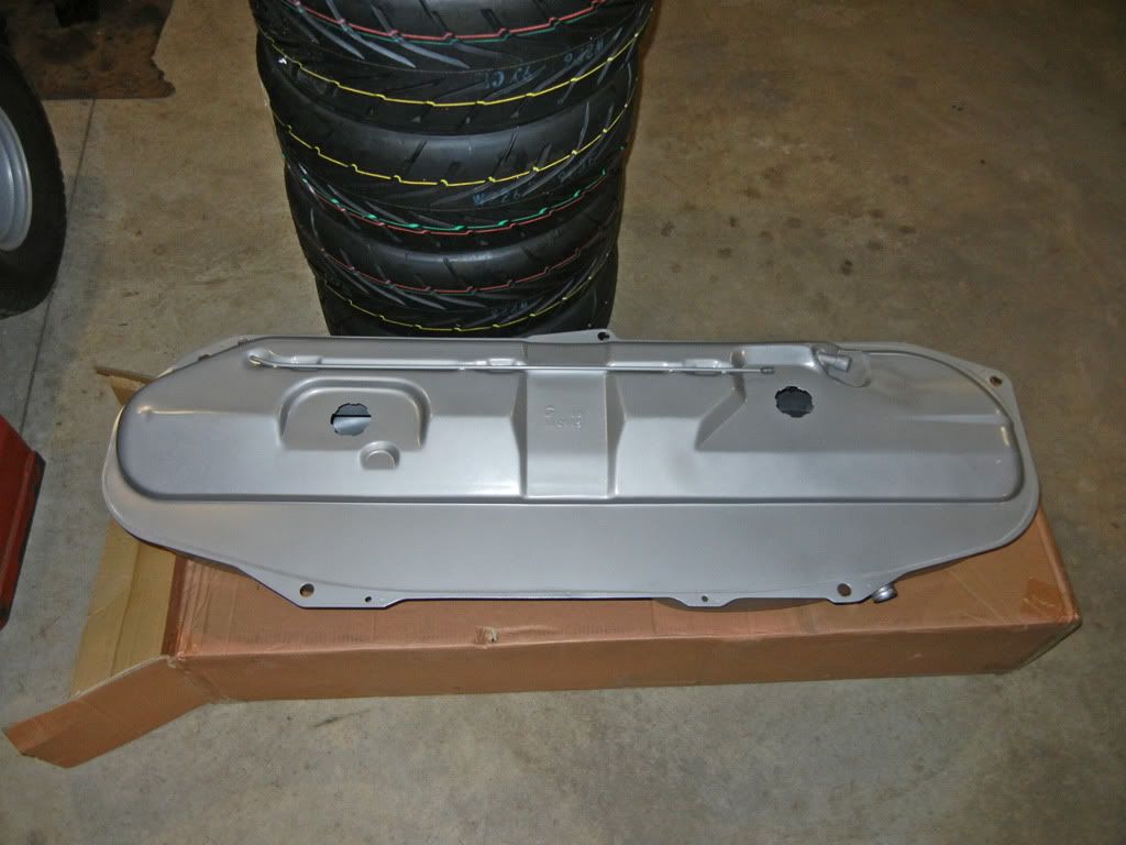
My current tank has a hole rotted on the top left side somewhere because when it's more than half full a quick left will leave the cabin with the smell of spilt gas. I figured if I'm going to be dropping the exhaust and drive shaft to swap the motor it will be as good a time as any to swap the tank out...
And to finish off the update, I'm almost done making the adjustable cam gear. I just need to drill and tap the holes around the outside and then separate the gear into two pieces...
I'm going to try and get the head assembled this weekend and then finish up the cam gear on Monday so I can work on setting the timing and checking the valve to piston clearance next week.Leave a comment:
-
Technically yes, but since the largest variance in hole location from side to side is only +/- 3 degrees on a short radius and the amount of material being removed is pretty small relative to the overall weight the result is that the center of gravity shifted off of the rotational axis by 0.006mm... so pretty much nothing :-)Originally posted by BMW_325i View PostLeave a comment:
-
You must think you are soooo smart coming up with that ^^^
And you would be right!
Could the uneven spacing of the holes cause an imbalance?Leave a comment:
-
Thirdly, I was thinking about the adjustable cam gear yesterday and how I would go about making adjustments. All the after-market gears have a degree scale etched into them, but I don't have the tools to do that. I thought about just printing a scale that I could just laminate and glue on and use with the existing timing line on the gear, yeah kind of ghetto but it would work. Then I thought about how pretty much all mechanical timing adjustments rely on the accuracy of the eye of the person making the adjustment. I figured it’d be nice if there was a quick, easy, and above all fool proof way to make timing adjustments. I came up with this concept…
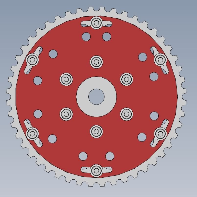
At this point you might be wondering what those extra holes are for. Looking at the timing gear I figured that the manufacturing tolerance of the gear was at least as good as (or better) than the accuracy of the human eye so why not use the physical geometry of the gear to dictate the timing adjustment. Obviously when I go to machine the gear I will verify if my assumption was acceptable or not. This picture will give you a better idea of what is going on…
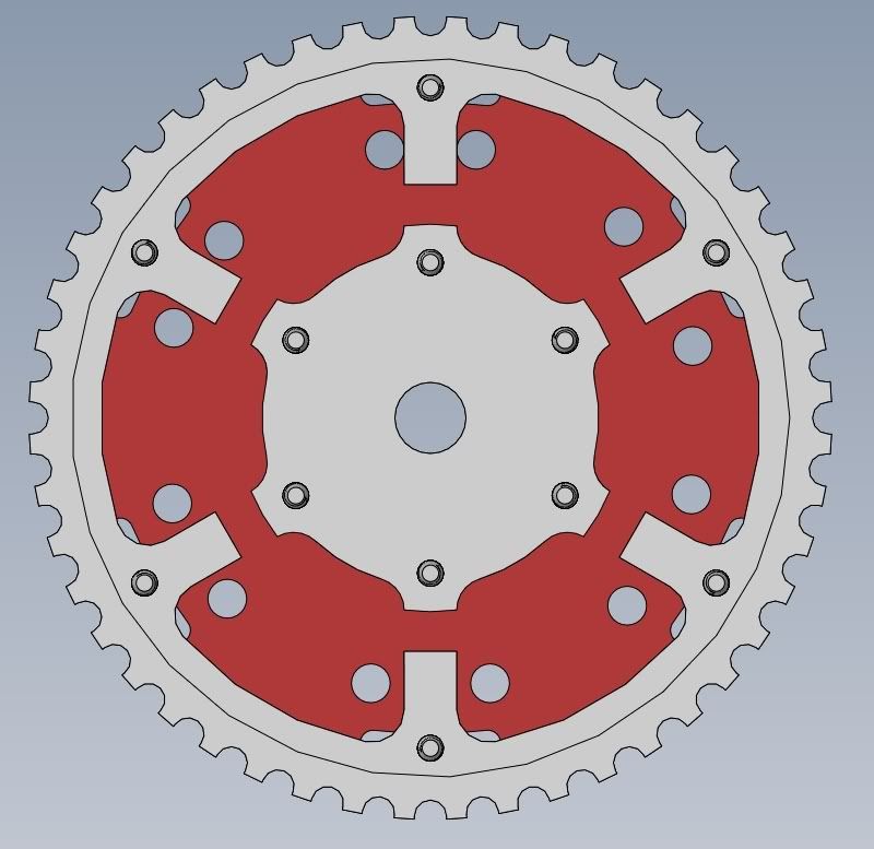
As you can see, my idea was to use the spokes of the timing gear to adjust timing. The holes in the plate will be reamed to 6mm to have a nice snug fit for a 6mm dowel pin. That way I will be able to insert a dowel pin into a hole, loosen the screws around the outside and rotate the gear until the dowel pin contacts the spoke. One spoke is used to set the orientation of the gear back to stock timing and the other spokes can advance or retard the timing 1 degree per spoke. So this layout gives me +/- 5 degrees of timing adjustment on the cam which correlates to +/- 10 degrees on the crank, however the holes could be revised to give any combination of advance and retard. Hopefully it works!
That’s all for now folks!Last edited by Bullet Ride; 05-23-2013, 08:33 AM.Leave a comment:
-
In Flames We Trust :up:Originally posted by Wh33lhop View PostLeave a comment:
-
Great thread, I love in depth stuff.
Curious, your screen name reminds me of an In Flames song, are you a metalhead?Leave a comment:
-
If you have experience soldering things before it's not to bad. Some of the components are pretty small, but none of it is sms. If you haven't really soldered anything else before I would probably practice on a less expensive project before hand just to make sure you really have the hang of it.Leave a comment:
-
Define the range of the scale for me ;)Originally posted by acolella76 View Post
I'll say this, if you can build a motor you can build this kit. You just need some patience, a soldering iron with a nice small tip, and some good solder. The first time I built one I did it in a weekend. This time around I did it in about 4-5 hours between two evenings. You don't even have to use most of the components that come with it, when you first unpack the kit it it looks a lot more daunting than it actually is because there are a lot of components.
You just figure out what circuits you need to build and then follow the general assembly procedure on the website but only install the components you need. If you look at this picture...
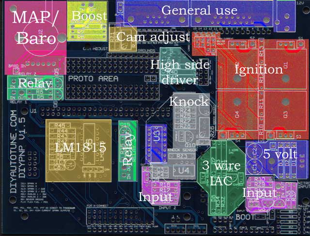
You don't need the boost control circuit (unless you plan on boosting :p), cam adjust, LM1815, or knock. As you can see that doesn't leave very much to install. Most of the work is done by the microsquirt module which comes pre-built.
This is a picture of the board with all the components you need installed (minus the LM1815 circuit) before you solder on the header for the microsquirt

Then you install the microsquirt module...

Then the hardest part is doing the jumpers because keeping the wires in place while you try to solder them can be finicky...

Leave a comment:
Leave a comment: