Announcement

Collapse
No announcement yet.

Please help w/starter wiring - diagram attached

Collapse
X
 
  • Filter
  • Time
  • Show
Clear All
new posts

    Please help w/starter wiring - diagram attached

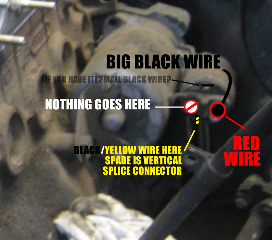
    A while back the starter went bad in my 1989 325ix, so I swapped it out for a new one. After wiring the starter and re-assembling the intake assembly, I found that the starter would crank but the car would not start. There was spark at the plugs but no fuel at the rail. Have I attached the starter solenoid wiring incorrectly? Here's a diagram:

    Click image for larger version

Name:	image.jpg
Views:	1
Size:	84.6 KB
ID:	7244606

    Any thoughts??

    Thanks in advance!

    Toby Carlson
    Spokane, Washington

    #2

    Comment


      #3
      I have three inputs on the starter and four wires. The photo in the old string shows two inputs and three wires.

      Comment


        #4
        Small little black wire on top is for the unloader relay, I believe.

        Your diagram looks correct to me. I'd be suspect of the starter causing fuel issues without some strange making-it-really-hard-to-troubleshoot electrical demonry.

        I'd check fuses/relays for fuel -- I had a similar issue where I did a lot of work on the car and wouldn't start...issue was unrelated to the work I had done -- bad fuses happen. Is the fuel pump a-pumpin? Is there fuel in the device? haha.

        I'd also give a look see at the engine speed sensor and the reference sensor, maybe you bumped something -- the plastic on those connectors gets brittle.

        Comment


          #5
          The starter isn't going to have any affect of the no fuel (and probably no spark) condition.

          For the engine to run the following conditions must be met:

          Power on DME pins:
          27 Start Input
          18 Un-switched Power input
          37 Power Input from Main Relay

          Ground on DME pins 2, 14, 19, 24

          Timing data from the CPS on DME pins 47 & 48 from a rotating engine

          To have spark power must be present at the coil positive and ground pulses
          from the DME's pin 1 must reach the coil negative. Power to the coil is
          controlled by the ignition switch via C101. When checking for spark, use the
          output lead from the coil to eliminate the distributor, rotor and plug wires.

          To have injector firing power must be present at each injector and ground
          pulses from the DME's pin 16 (Bank1) and pin 17 (Bank2) must reach the
          respective injector bank. Note that the injectors are wired as two banks of
          three. With cylinder 1,3,5 being bank 1 and 2,4,6 being bank 2. Power to the
          injectors is controlled by the main relay. Injector firing is best checked
          with a noid light.

          The fuel pump relay must have power on pin 86 (relay coil) from the main relay
          output (pin 87) and power on pin 30. The DME will ground pin 85 to turn on the
          relay and power the pump(s) via pin 87. Of the above, only the fuel pump power
          is fused. So if the there's power at pin 87, but not at the pump, check fuse
          11.

          The main relay and DME pin 18 receive power from the smaller of the two wires
          that connect to the battery's positive terminal. That wire incorporates an
          in-line fuse. When the DME is presented with a start signal, it grounds the
          main relay pin 85 and furnishes power to the fuel pump relay, injectors, and
          DME.

          Troubleshooting:

          Disconnect the battery and the DME cable. Then:

          1) Disconnect the coil negative and check continuity from that connector to
          DME pin 1. Also verify that from DME pin 1 to ground is an open circuit.

          2) Check the resistance across DME 47 & 48, which should be 500-560 ohms. If
          the CPS is dismounted, the resistance can be seen to change from about 500 to
          540-560 ohms when a ferrous object is brought to the face of the
          sensor. Neither pin should be grounded.

          3) Check for continuity from DME 36 to main relay 85 and from DME 3 to fuel
          pump relay 85.

          Reconnect the coil, remount the CPS (air gap should be 1mm), plug the
          relays back in, reconnect the DME, and connect the battery. Then do the
          following checks:

          1) With the key off, verify that power is present at DME pin 18 and main relay
          86 & 30.

          2) With the key on, verify that power is present at DME pin 27 and pin
          18. Power to pin 18 is from the main relay and there should be power to the
          injectors and fuel pump relay.

          3) With the key on, verify that no voltage is present at the DME grounds (2,
          14, 19, 24).

          4) Verify that power is present at the coil positive and at fuel pump relay
          pin 30. Those get switched power from the ignition switch via C101.

          The engine will start and run (if poorly) with only those connections to the
          DME in place. The other signals from Cylinder ID, AFM, temp sensor, etc., are
          necessary for proper operation. But they won't prevent the engine from firing.

          IMPORTANT:

          A power check means seeing a voltage within about a tenth of a volt of what
          you measure across the battery terminals, which should be at least 12.6v on a
          charged battery.

          A continuity check means seeing less that 1 ohm of resistance.

          An open circuit means seeing a resistance of at least 100k ohms.

          A good quality auto-ranging digital multimeter will make these tests much
          easier.
          The car makes it possible, but the driver makes it happen.
          Jim Levie, Huntsville, AL

          Comment


            #6
            http://www.r3vlimited.com/gallery/fi...te_harness.jpg

            http://img.photobucket.com/albums/v3...m/DSC07843.jpg

            Hope these help showing where the wires go.

            Comment


              #7
              Thanks very much, everyone. I do have a decent multimeter and will do the troubleshooting as soon as the weather cools some. Again, thanks!

              Comment

              Working...
              X