

I do not understand where the hose from the valve cover is going to. The diagram says it routes to the BOTTOM of the TB as below (the orange line going from the valve cover to the TB):

But here is the bottom of my throttle body. There are no ports to connect the hose to. There is just this bracket there.
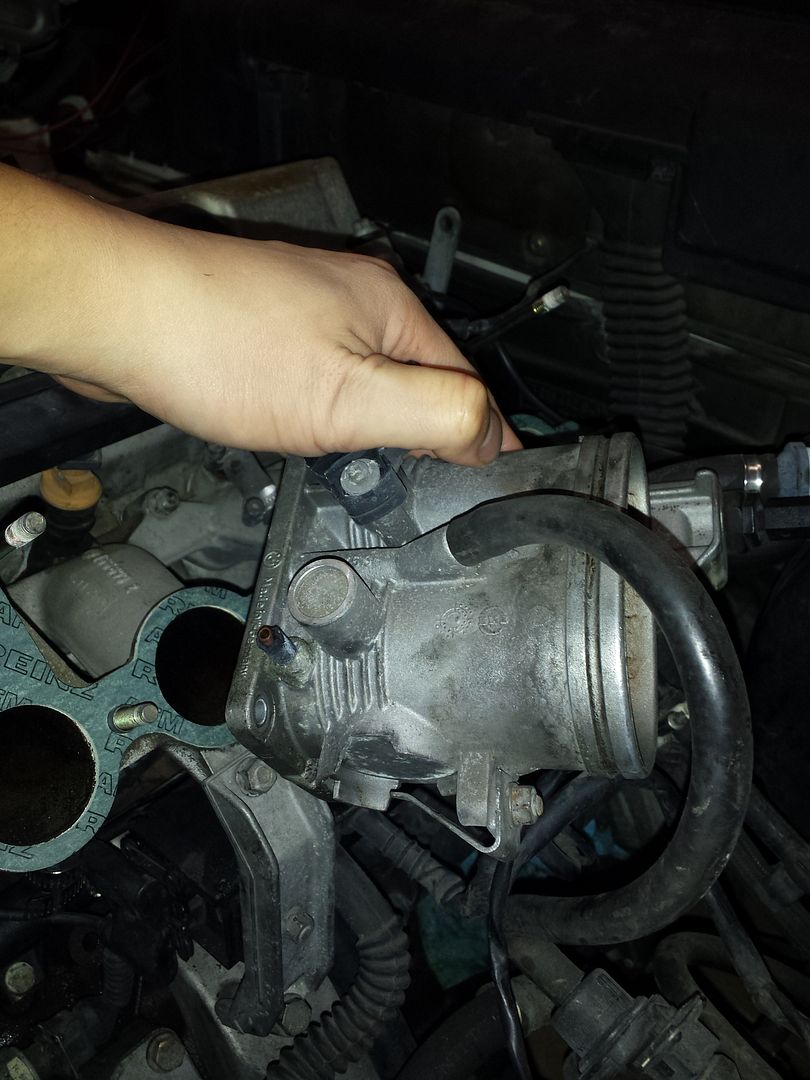
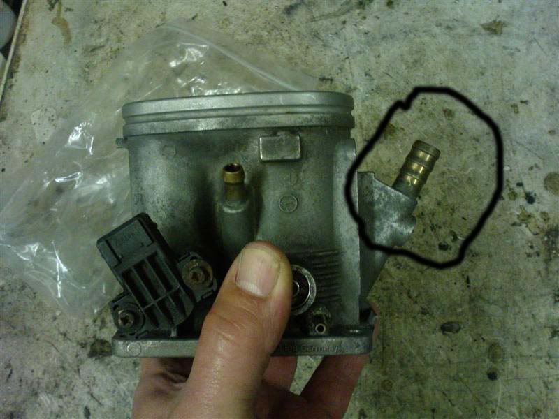
I think the bracket used to hold this thing.. maybe. Can't remember. Am I supposed to keep this weird plate hose thing on the bottom of the TB and connect one of the ports to the port on the valve cover? If so, what about the other port on the weird plate hose thing? Where does IT go?
[IMG]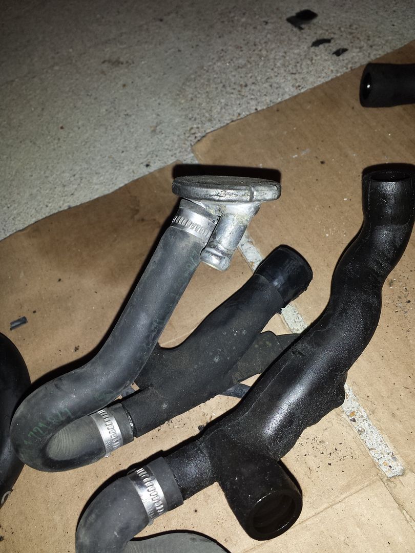 [/IMG]
But here is the bottom of my throttle body. There are no ports to connect the hose to. There is just this bracket there.

I think the bracket used to hold this thing.. maybe. Can't remember. Am I supposed to keep this weird plate hose thing on the bottom of the TB and connect one of the ports to the port on the valve cover? If so, what about the other port on the weird plate hose thing? Where does IT go?
[IMG]
 [/IMG]
Comment