

I didn't want to create a new thread for this so I'll tack on to this one. I know people such as JGood have had issues with Mishimoto in the past, I believe he settled on doing a Z3M S54 Behr radiator. I think I've found another aluminum radiator option in CSF Racing based out of Southern California.
Scroll down until you see the Other BMW Applications section. It looks like the 3054 radiator might work yeah? 1 5/8" core works out to be just under 42mm which is what the Behr unit is. Thoughts?
-
I dont want to start another thread so i'll post my question here as its still related to cooling. Whats everyone going with in terms of fans? Pusher style or puller style. I'm deleting AC so I'm thinking of doing a pusher fan. This would leave me with a bit of extra space in front of the pulleys.
Are there any advantages to pusher vs puller fans?Leave a comment:
-
Leave a comment:
-
Thats a huge help. Thank you. How did you cap off F on the coolant channel? Did you also weld it shut?
Edit: also to follow up on H, I did some more research and it appears that the hose for H is the pressure overflow bleed from the expansion tank. It does not connect to anything, it just drops down to the frame rail.Last edited by P Arkus; 11-03-2016, 10:58 AM.Leave a comment:
-
C goes to I
If your donor was an Automatic car, then E and G went to a transmission cooler below the car.
On mine, I used one for the tank, and I capped the other one. I'm also using an X5 reservoir though.
Like I said earlier, I think I goes to C
I'm not 100% with this tank, because I used the X5 tank, and blocked off one of the outlets.
How I have mine set up:
E to E
G to F(Heater core)
D to bottom of the tank
F on the coolant channel I have capped.
C to I
and I don't have an H.
Hope that helps.Leave a comment:
-
So I'm just a bit confused on the whole cooling system and where everything connects to on the swap. I've done so searching and got most of my answers but still unclear on a few things. These are the threads i'm mainly going off of for now:
I've also drawn up this crappy little diagram and hoping that you guys can help me out with the unknown pieces. I have the rear coolant pipe with the 4 nipples from an E34 540i
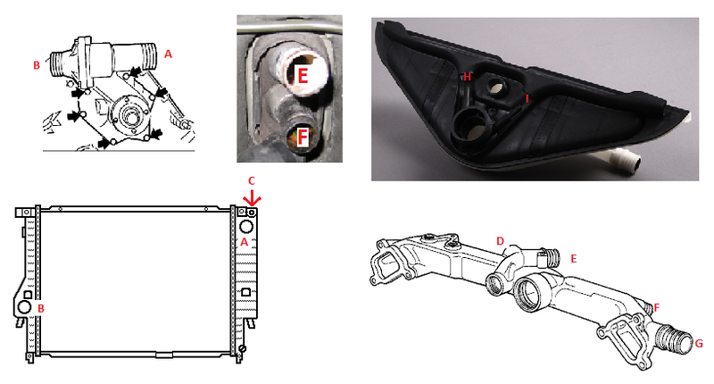
Can someone please let me know where the following connect to?
C) The nipple on the rad above the upper rad hose
D & G) I believe one of these goes to the expansion tank, where does the other go? I saw Jgood welded it shut, is that a requirement or a choice?
H & I) the 2 thin hoses on the top of the expansion tank?
Any help is appreciated, and also please let me know if I labelled something incorrectly on my diagram. I dont want to be giving any false info for people searching for this in the future.
Thanks!Last edited by P Arkus; 11-02-2016, 06:45 PM.Leave a comment:
-
-
-
I realize this is a necro-bump, but someone, somewhere will find this thread and the info in it useful (as I did). I am updating it with my schematic of the manifold and how it flows.
 Last edited by marshallnoise; 02-25-2016, 12:02 PM.
Leave a comment:
-
-
That answers everything, thanks. I didn't look at the manifold closely, I assumed it was all one big open passage. I'll refrain from asking more questions until I start putting the engine back together :)Leave a comment:
-
Okay goofy... look at the crossover manifold closely, specifically where the 2 tubes from the water pump go in. See how the smaller tube is segregated from the rest of the manifold? That keeps the heater core input and output separate, so the system continues to flow, instead of stagnate. If you are running heat, you need at minimum 2 outlets on the manifold, if your reservoir is also feeding into the manifold, you'll need 3. E38/39 setups are different, since the reservoir is at the front of the engine bay, the water pump has the 3rd nipple/inlet. I used an E38 manifold, so I only had to close off 2 nipples and then move 1 to the passenger side. I also drilled and tapped the bosses for the 2 temp sensors, which is easy to do. Any more ???, just LMK...:)
GareyLeave a comment:


Leave a comment: