
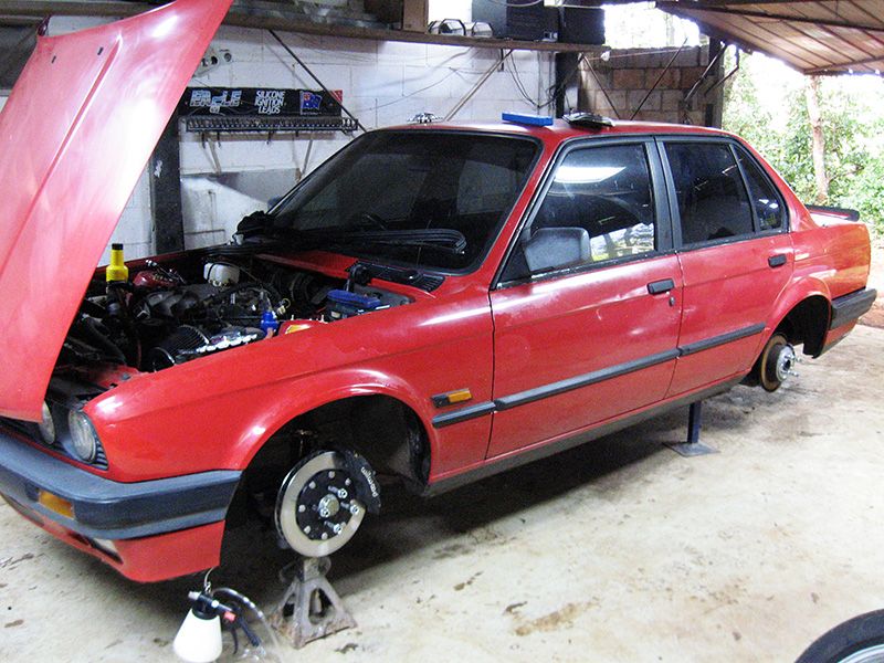
Been asked a few times about how I went about installing the tilton pedals into a RHD car. I honestly cannot find where the hell I moved all the photos to that show everything in detail step by step, but I did upload enough little previews along the way that I reckon I can piece together everything with sufficient enough detail to show people how I went about it if I can't find the rest of the photos.
Couple of things before I start. We have some strict laws here with regards to modifications. You can't just go chopping into the firewall or welding on it and expect it to be passed by an engineer, meaning your modifications won't be legal which means you cant register/insure/drive your car on the street.
Because of this, in discussions with the engineer who was to approve the mods and plate them (get a little blue plate that mounts in your engine bay that says the vehicle has been mod plated and the modifications have been passed), the only way he would allow such extensive changes without causing issue under the rules would be to try and utilise as many as the factory bmw mounting points as possible. He wouldn't have a problem signing off on it if it looked to use the same mounting points as standard. We had a big discussion about just how strong these points really are, the end result was he pretty much agreed with me, the firewall will flex a hell of a lot (and it already does on the stock pedals), but from a legal stand point it will cause the least amount of trouble if anything is ever inspected.
We talked a little about positioning and how to mount the pedals properly, had a look at some other overhung designs and how he had mounted them previously, decided it was pretty easy to make a mount for the underside of the pedals that is mounted through the firewall and braced through the top of the pedal mounts.
With this in mind, everything was way over spec as far as stiffness and plate thickness. I was using the 6.2:1 longer throw tilton 600 series overhung pedal set (new part # is 72-608 ), no booster and I have huge legs to stamp on the pedals. When coupled with the flex in the firewall everything would be oversized, then when the car is pulled down later on to paint, I was going to remake the pedal box in slightly thinner materials where it could be sacrified (mainly around the bracing and probably 5mm plate for the firewall mount).
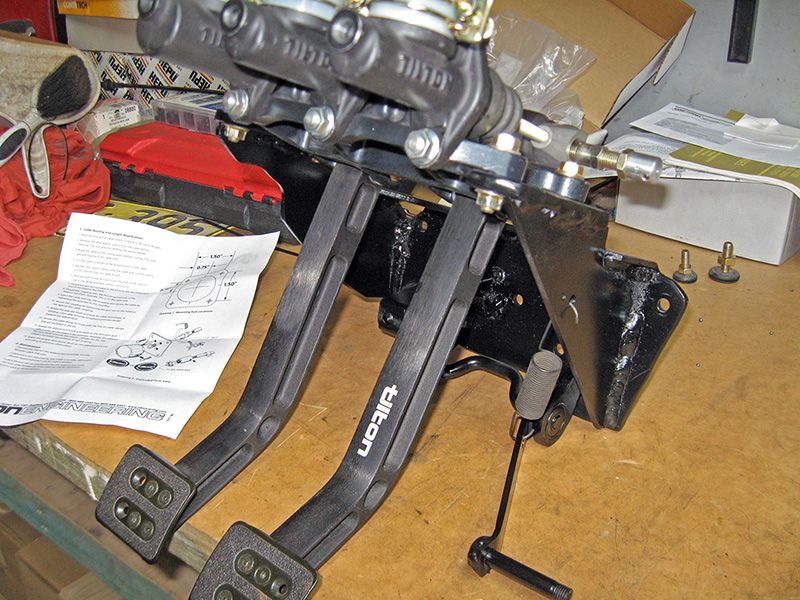
I started it all when a package arrived from summitracing. Much head scratching followed.
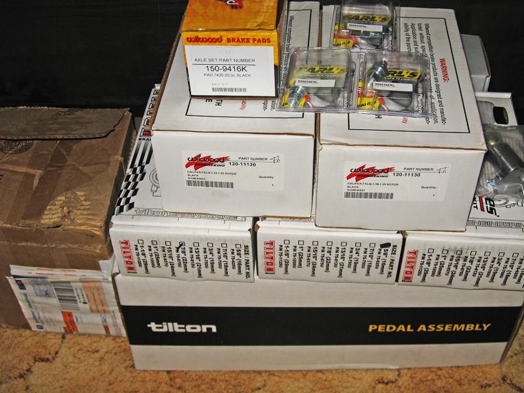

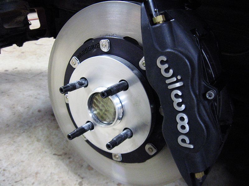
Brake Setup on the car
Tilton 600 Series Alloy Overhung Pedal Set 6.2:1 Ratio (72-602)
Tilton 75 Series Short Master Cylinders.
-5/8" for front and rear brake master cylinders (75-625U)
-7/8" for clutch master cylinder (75-875U)
**Note** This is really sized to suit the V8 clutch going in later, id recommend running something much smaller around 3/4" or if running with a bmw engine (228/240mm clutch). The pedal is very heavy with the 7/8" cylinder (as I expected it to be).
Wilwood Adjustable Proportioning Valve (260-12627)
Massive Brakes 300x32mm front brake kit.
Wilwood Forged Super lite Caliper, 1.38" pistons (120-11130)
Wilwood BP20 Pads (150-9416K).
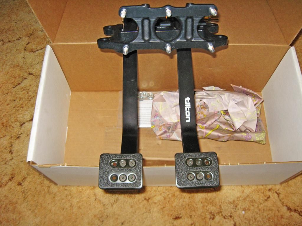
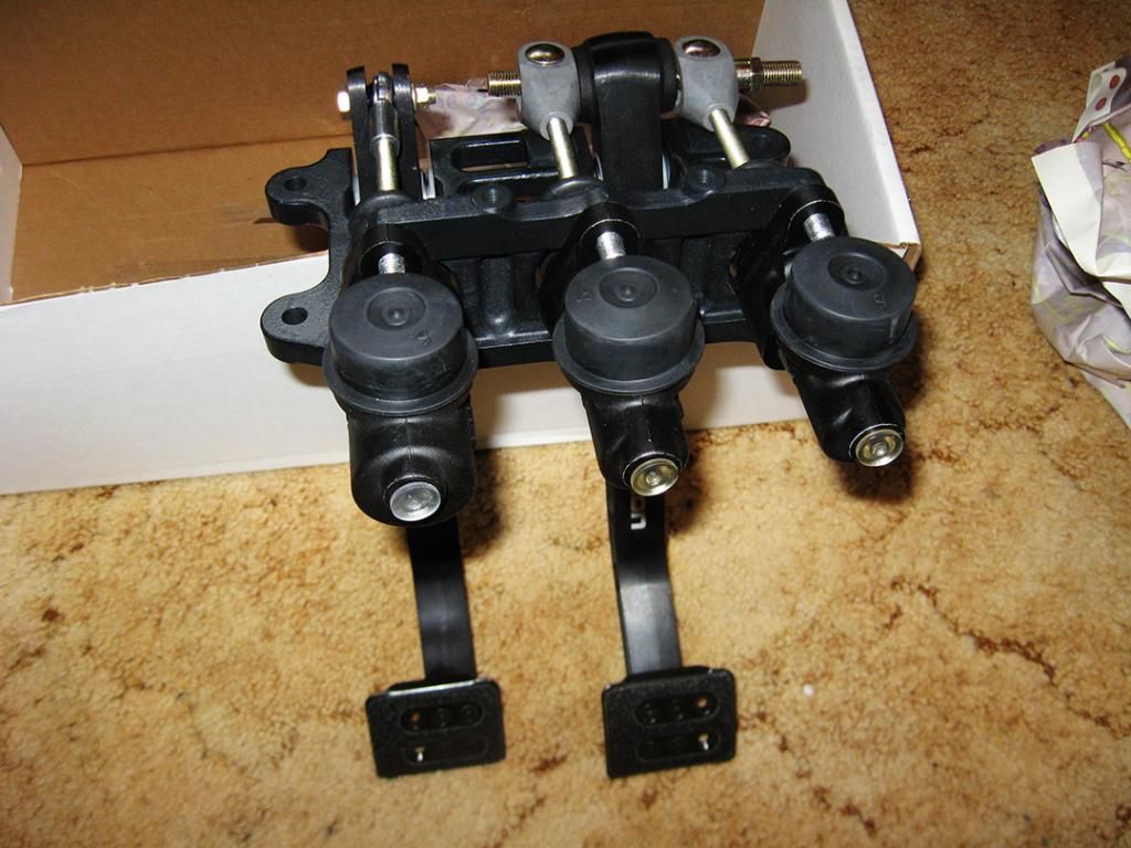
It was evident from the beginning that the 6.2:1 ratio pedals were a LOT longer than I had realised and the space in the E30 is a LOT smaller than expected. The challenge was to mount the pedal box as high as possible to maintain plenty of space under the pedals between the floor pan (and providing good contact on the pedals), but the master cylinders couldn't be so high the remote reservoirs wouldn't feed them properly. Not to mention the whole lot had to be tucked under the dash like it was factory as we couldn't go cutting holes in the dash either!
I started by cutting a piece of 4mm plate to mount through the upper mounts on the tilton pedals and the two upper bolt positions for the factory pedal box. This is essentially a brace they recommend you utilise when doing the install, but I started with it to be able to position the pedals where I wanted them.
I basically redrilled this plate a few times to reposition the pedals exactly where I wanted them. The result was good with regards to position, but the angle on the pedals was kind of extreme with the plate flat and provided next to no room under the steering column mount, so I heated it up and tweaked it a little in a vice to tilt the pedals down a little more and gain some space. Once I was satisfied with fitment, I remade this plate with just the pair of mounting holes needed.
I had to notch the side of the steering column mount a little to provide space for the bolt hole.
With that done I took the original pedal box and made a template of the plate that mounts flat to the firewall.

Because of the flex in the firewall, I used some heavy duty 7mm plate for this mount to help spread the load (more bracing to follow later). I cut it out exactly the same shape as the factory pedal box and drilled all the holes to suit. I mounted everything identical and used the same factory high tensile bolts.
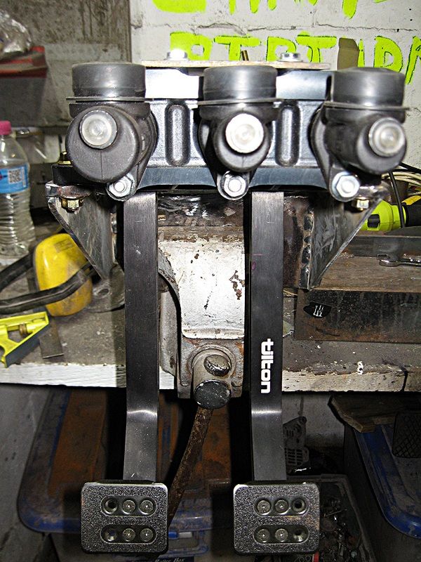
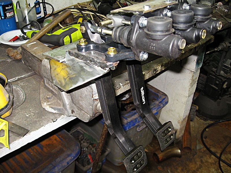
The pedals were hung from the top and positioned and I had the mount on the firewall, so i had to start by joining the two up. I took some more of the 7mm plate and cut two rectangle strips 35mm wide to be used as the underside mounts on the tilton pedals. I cut them just long enough to sit past either side of the tilton mounts, so basically visualise them as being like seat rails running down each side. I drilled them per the mount spacings on the spec sheet tilton provided and mounted them to the underside of the pedals with high tensile bolts.
This provided me with a couple of legs to weld down braces to and would basically form the mounts for the pedals. I took out some cardboard and made some templates in the shape of triangles that ran from the plate on the firewall to each of the mounts on the underside of the pedals. The underside of the firewall has a rib that runs along it, so I had to take a notch out of the top side of the down braces to clear. I cut them out of 4mm plate steel and positioned them in place. I had to hand file them a little to get things perfect, but once positioned properly I tacked everything in place.
I then unbolted everything and removed it from the car at which point I started to think a little more about rigidity. I decided I could kill two birds with one stone, cross brace the pedal box itself and provide a third mounting location through the firewall which would pretty much completely eliminate any flex in the pedal box at all. End result was just behind the pedals themselves, I ran another piece of 4mm plate across both sides of the down braces. This tied them together and positioned this plate directly under the rib in the firewall (basically where the battery tray mount is on cars with batteries in the engine bay). I could now use a plate on the outer side of the engine bay to space the load, drill right through the firewall and into the pedal box, and sandwich the whole lot together with high tensile bolts so the whole thing would be completely supported in 3 places.
I was pretty happy with the fitment until I put the box back in the car. It was pretty difficult to get the whole lot back in there, the down brace on the left side came really close to the shaft in the steering column and you kind of had to twist and turn the pedal box to get around it. It pissed me off so much I ended up taking a notch out of the left side so the whole lot could just slide in nice and easily, completely missing the steering column.
I welded everything together in larger stitches. That's why the welds look a little start stop. Basically, dealing with so much heat It would start to distort the plate and throw everything off alignment wise with the holes, so I welded a bit on each plate at a time to keep the heat down to a minimum. Next time I make one for an E30 I will make a template welded to my steel bench so I can mount all the pieces to the bench to hold them solid while welding. Still, I was pretty happy with the end result.

Everything was solid, mounted it all back in the car and had a look at how to deal with the throttle pedal. I intended to run the M20 for awhile, upgrading the rest of the car before swapping the V8 in, so I had to do something about the throttle pedal.
I hate the stupid bush setup of the factory one, just about every E30 I've ever driven has so much play in the throttle it's ridiculous. I decided the best solution was to bearing mount each end of the throttle shaft, replicating its position from the factory pedal box onto the new one I made.
I raided my local parts shop for some bearings with a 10mm ID to suit the shaft. I cut the original throttle linkage off the factory box, shortened it and made some mounts to hold the bearings out of the 7mm plate I had before. They were basically just two rectangles cut on an angle at the bottom to mount the throttle in the same rough position/spacing as the factory.
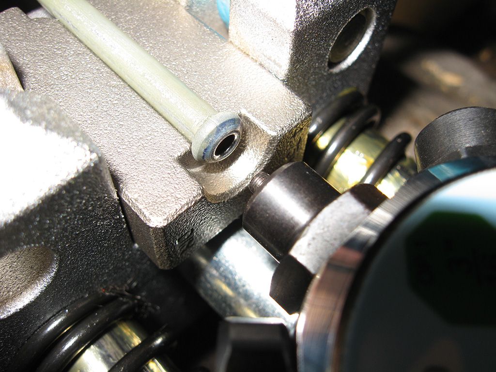
On the lathe I turned down a couple of rings the same OD as the bearings, giving me something I could weld to the throttle pedal mounts to mount the bearings without transmitting all the heat into the bearings themselves (like if you were to just tack the bearings in place in the mounts). It's basically more like a sleeve mounted in place giving you somewhere to install the bearings. With the mounts in place, I simply pressed the bearings into the rings and slid the throttle linkage into place. The only thing to note is, if you ever want to remove the throttle linkage from the pedal box without cutting, you have to make sure you space the mounts far enough apart so you can slide the throttle pedal linkage out if you need to just like in the factory pedal box. It's simple as the linkage was designed to be supported with clips on either end to stop it moving once in place. It's just a simple process of spacing the linkage out with some washers so if you wish to remove the throttle linkage, you just pop the clips off the end, remove the washers and slide the whole linkage to the side, out of the bearing at one end, then slide it back the other direction out of the bearing on the other side. Pretty simple when you have it in front of you. Of course, I honestly don't ever expect these bearings to wear out and needing to be replaced, so you can pretty much ignore the above if you want.
I drilled some holes in the down brace on the right hand side to play around with the position of the throttle return spring. Because the whole lot was bearing mounted now, i found it pretty much needed no spring tension at all to snap the throttle closed. Originally I took the factory pedal box and measured the length of the spring when the throttle was closed, replicating this on to the new one I had made, but wow... pedal snapped closed with so much force you could hear the butterfly crying in pain inside the throttle body.
Needless to say, drilled a new hole about 10mm closer, relieving the spring tension. End result, the throttle was butter smooth and didn't snap back at you!
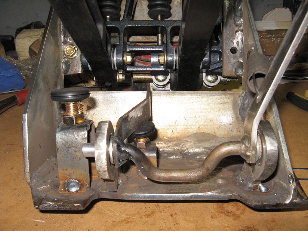
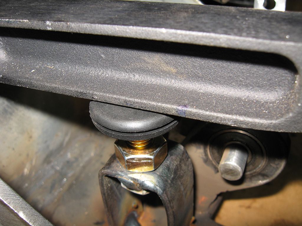
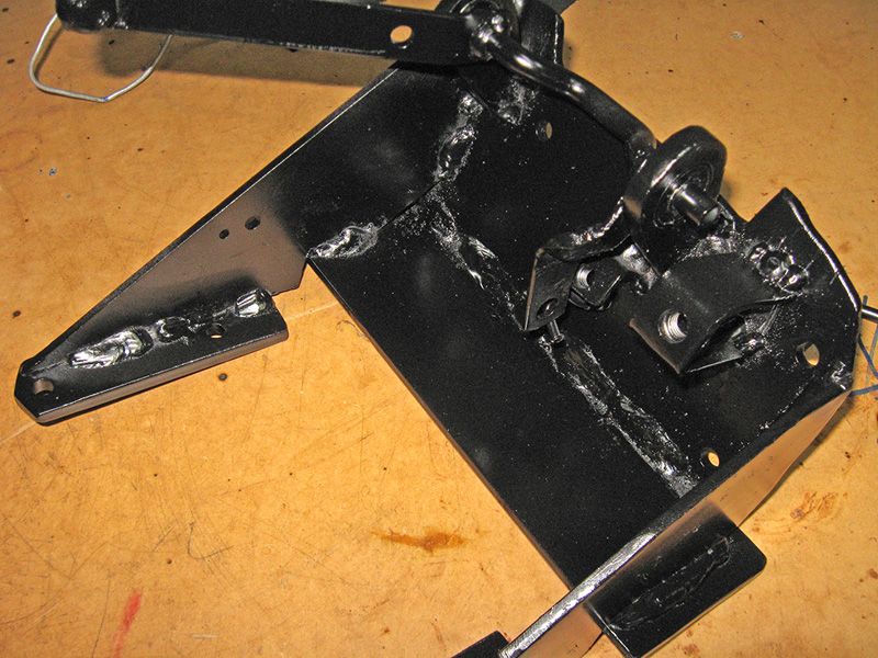
All that was left to do was to make some clutch and throttle stops. I simply bent some 2mm plate steel I had into U channel shape to form brackets. Found the size bolt I wished to use as the stop, then drilled through the plate and tacked a nut on the underside. I simply welded the bent bracket to the pedal box, placed another nut on the bolt I used, then screwed the bolt into place. When I had the length right to set the stop, it is a simple case of just tightening the second nut down to the bracket and locking the bolt in place. I epoxied some nice rubber bungs to the heads of the bolts to provide a soft surface for the pedal and throttle linkage to stop against. You can see them in the background to the right in the above photo :)
The only thing left to do was to make a bracket on the firewall side for the plastic bracket/bung/clip/stupid thing the factory throttle cable uses. In the factory pedal box it mounted through the pedal box in a square hole. Because the firewall plate in mine is so thick, that was never going to happen. Again, basically just made a bracket similar to the stops above, but filed one side down so I could slide the clip into place. You could avoid all this by simply taking the factory throttle cable to any cable services place, have them remove the stupid clip off the end and fit a usual pass through fitting, or you could fit any length cable you want for what ever install you are doing. I just did this because I thought it would work fine and decided I would try it first before having the cable modified. It's still in the car today and works flawlessly.
More or less looked like this when finished.
Next up was to start bending the brake lines, fit the remote reservoirs and bolt everything up.
I made my own brake lines as I have a proper vice mounted flaring tool. I decided I would use the existing hole in the side of the firewall (where the AC lines pass through) for the brake hard lines to pass through instead of drilling through the firewall. I took some thick solder (yes, the tin type) and used it as a template for the length of my brake lines.
I decided early on that I was going to mount the reservoirs, the junctions/fittings for the brake and clutch lines, and the bias adjuster in the engine bay where the battery would normally otherwise sit. I had also decided to use a brake light pressure switch as the tilton pedals I used don't have provisions for mounting a brake light pedal switch, meaning you would have to make a bracket to try and replicate the factory switch setup (which blows). Easier solution was to use a VW golf/beetle/porsche 911 3 pin brake light switch. This switch has both NC (normally closed) and NO (normally open) circuits on the same switch. Perfect as BMW use a NC switch, but mount it in reverse, so when the switch is pressed like when the brake pedal is at rest, it is open. When you press the pedal, the switch releases and is now closed, turning on the brake lights. I also wanted to keep as much of the brake and clutch system metric, like the factory M10x1.0mm lines in use, so everything but the fittings on the master cylinders is metric (these are -3AN like the master cylinders)
Making brake lines is kind of easy with the right tools. I cannot overstate how important it is to have a good flaring tool, it honestly makes all the difference. Likewise, decent quality brake tube is great too, some stuff you get is really hard and difficult to bend. The good stuff can be bent fairly easily by hand.
Start by taking your brake line templates and cutting your new brake line tube (3/16") to length with a tube cutter. I use the wheel type that wraps around the tube, if you go slow only increasing the cutting depth by small amounts, I find it gives really nice cuts that only need a very slight dressing before use.
Slide over a new brake nut.
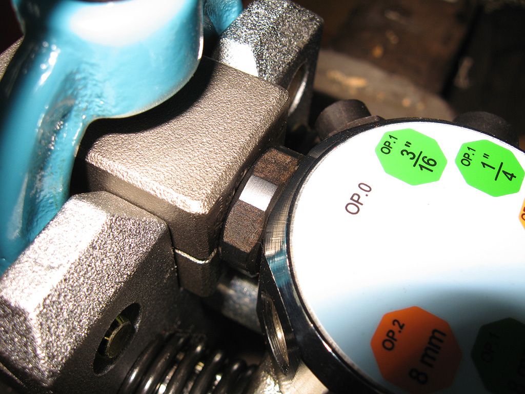
Select the die and position the tube inside.

Tighten down the clamp a little, but leave it slightly loose so the tube can still move inside the die. What you do here is select the flat section on the flaring tool, then pull the lever like you were doing a flare. This positions the die and the tube perfectly in the flaring tool. You then tighten down the clamp completely and release the handle on the flaring tool returning the block back to the normal position. The end result is the tube should be square and sitting perfectly flush with the end of the die, ready to punch out the flare.
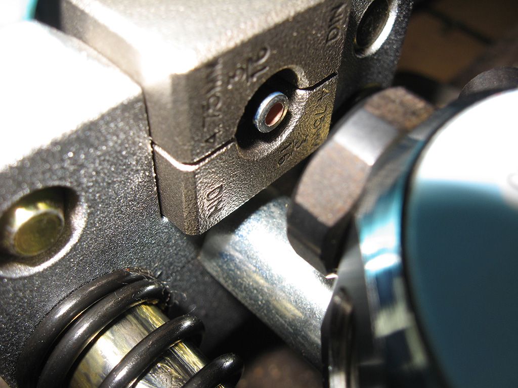
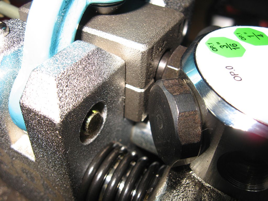
Select the proper punch from the block (3/16 OP1 = single bubble flare). Grab the handle and in a nice smooth motion, pull the handle all the way, driving the punch into the tube until you can't pull any further. You'll feel some resistance, but you need to make sure you press it all the way to the end of the die. You need a bit of force to make the flare correctly, but don't go hanging off the handle either.
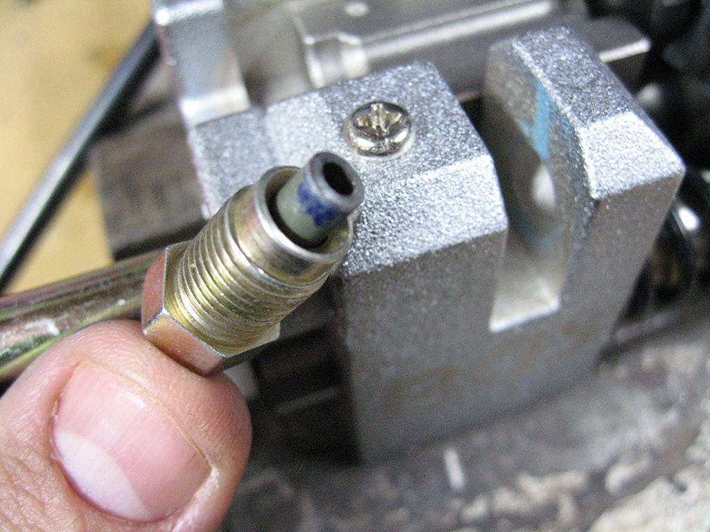
Release the handle and return the block to the start position, remove the die and have a look at your newly formed flare.
It was at this point I wasn't happy with the -3AN to metric M10x1.0 adapters I had used in the master cylinders. Just too much hanging off the front and kind of messy and bulky, so I ordered some -3AN brake nuts instead and decided that this would be the only part of the lines with different fittings. So I simply swapped the tube nut out, then flared the other end of the tube, so I had a new straight brake line with tube nuts fitted.
I simply bent the tube up to match my templates using a combination of hand tube benders and simply my hands. It's not exactly as perfectly bent as factory made ones, but I think it does the job well enough.
Just remember, if you have tight bends in the start of your lines you need to flare the line and install the tube nuts BEFORE you bend the hard line. You need a good 3 inches of straight pipe to flare them properly, so if you make the bends you'll find the pipe won't fit in the flaring tool.
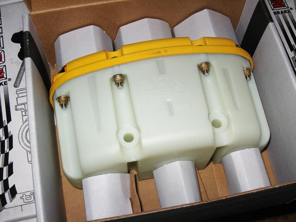
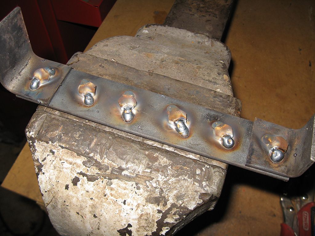
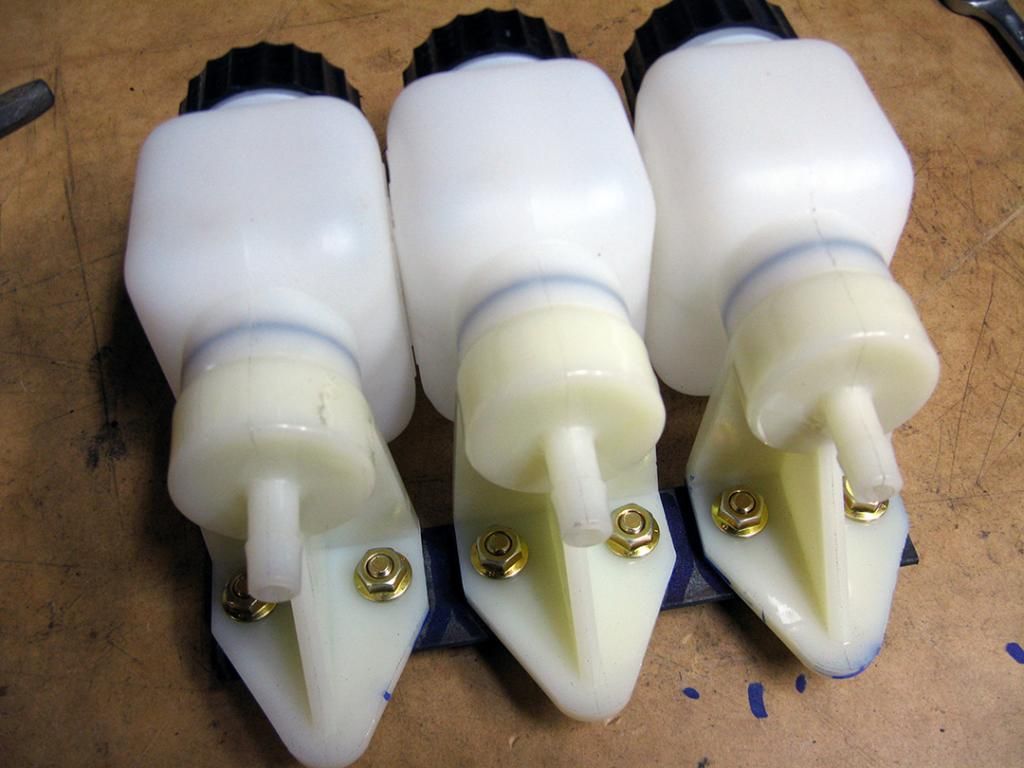
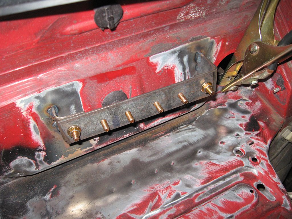
With the hard lines flared and bent to suit. I made a simple bracket up to mount the remote reservoirs. I originally purchased a nice 3 chamber tilton racing one, but I found I just couldn't mount it high enough to make sure the fluid flowed properly, so I decided to just use the larger remote reservoirs provided in the 75 series master cylinder kit. The mount itself is just flat 2mm steel plate with a bunch of M8x25mm bolts tacked on the underside. This way you don't have to try and get a spanner in behind the bracket when you want to remove them.
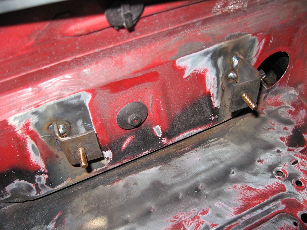
To mount the whole lot to the outside of the firewall, I simply made a couple of L shaped brackets up, bolted one on each side of the reservoir bracket above, then welded the L shaped ones to the firewall. To remove the reservoirs on their bracket complete, all you do is remove the nut from both ends and the whole bracket and reservoirs comes off, attached.
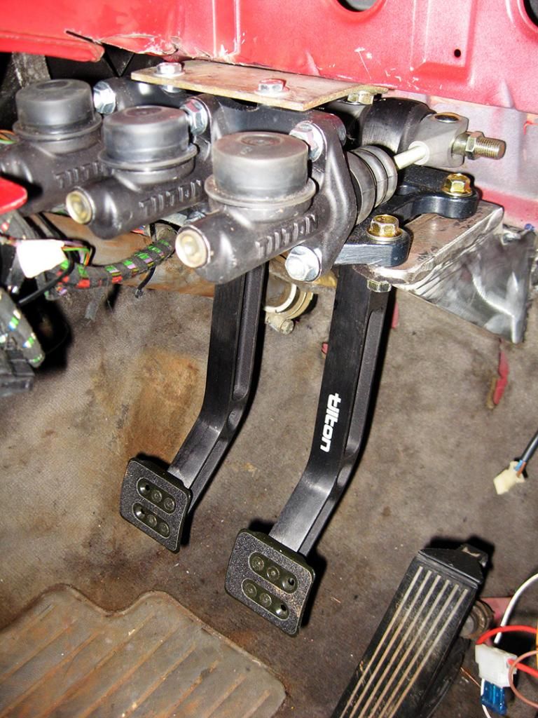
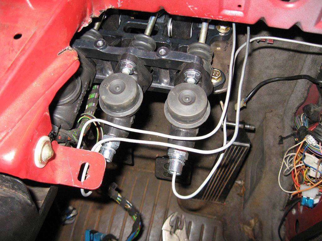
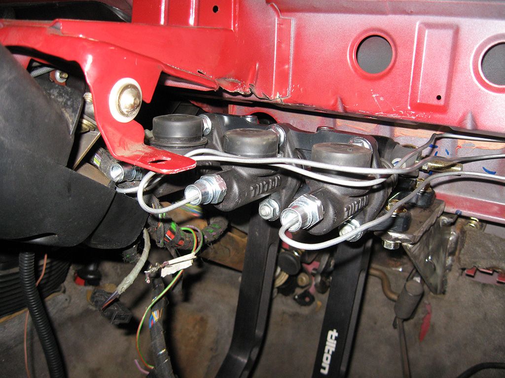
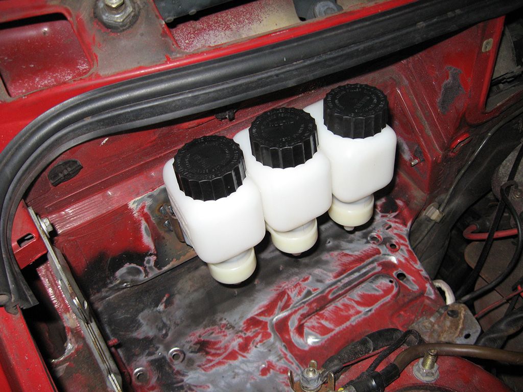
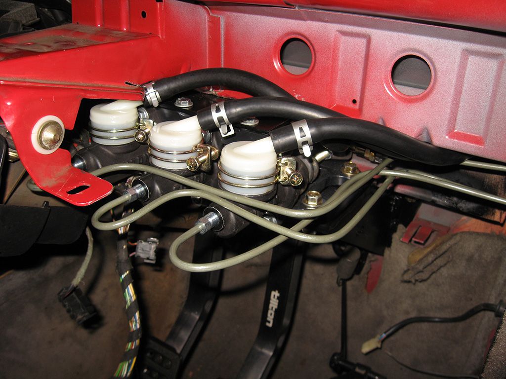
With the whole lot installed.
I made up a simple bracket in the engine bay to bolt the rear proportioning valve to. End result with everything in place.
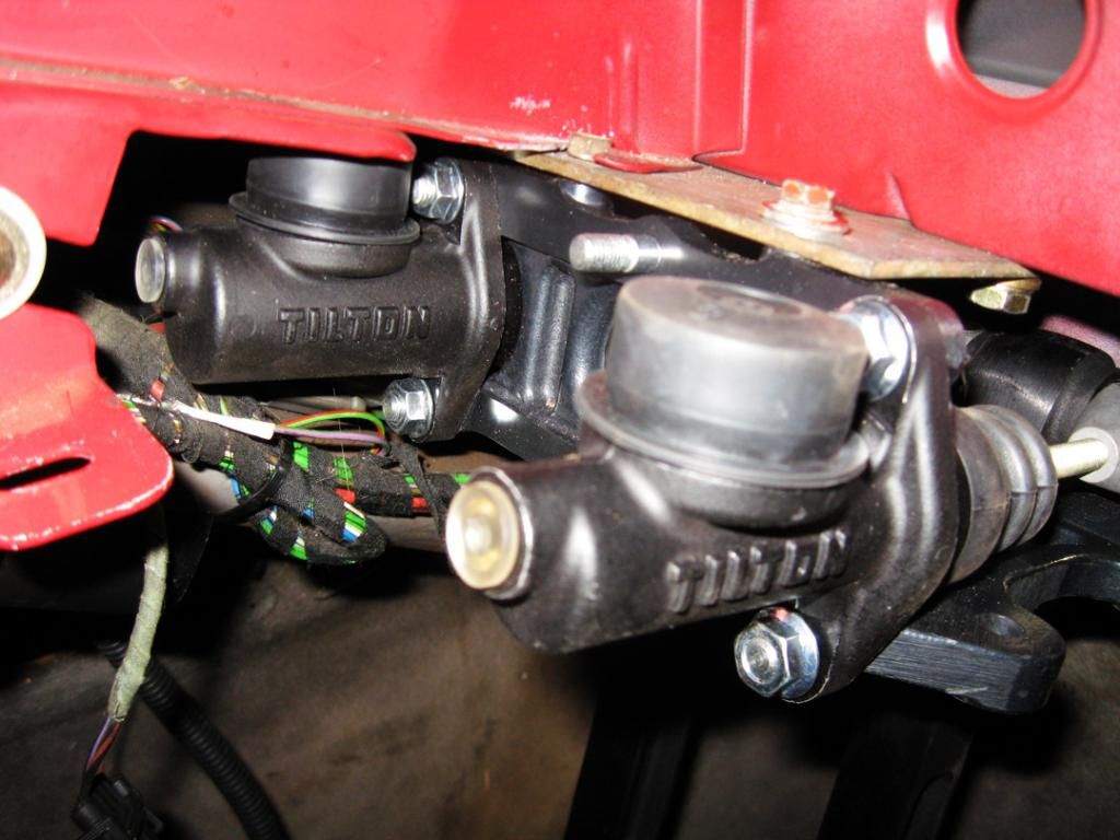
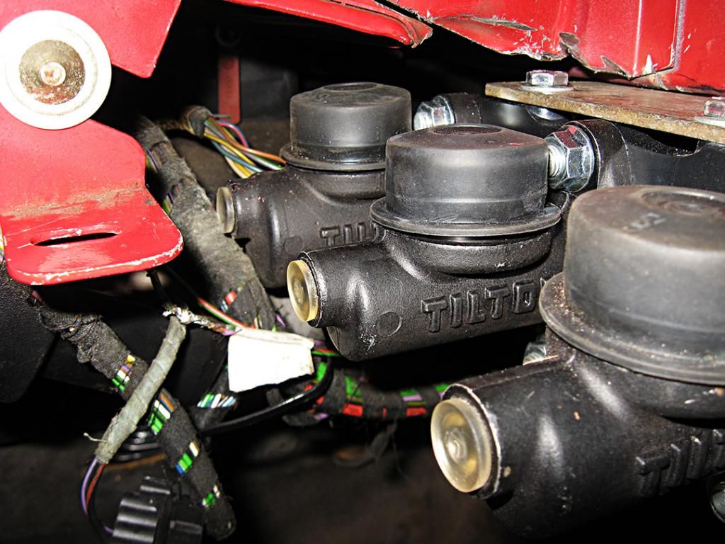
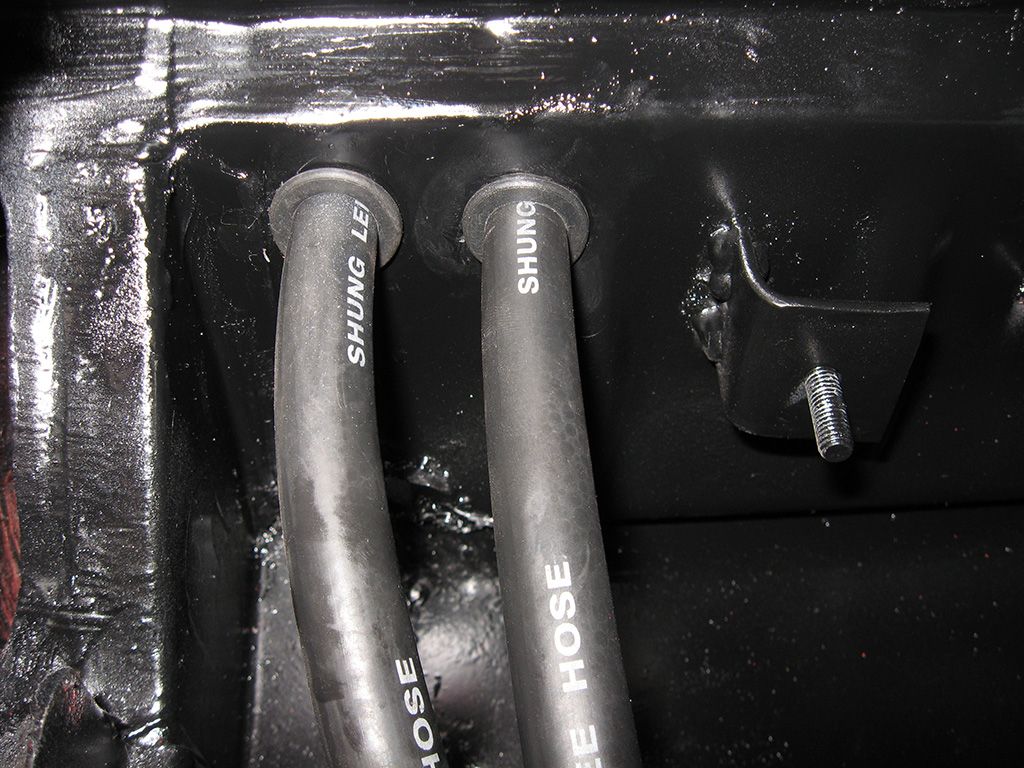
Next up was to attach the caps to the master cylinders for the remote reservoirs. Simple case of running a little brake fluid around the seal, then pressing the cap down over the master cylinder. They are then fixed in place with a strap type clamp provided in the kit. I worked out where I wanted to position the fluid lines for the reservoirs and drilled some holes through the firewall to locate them. I slide a rubber grommet over the fluid line to protect it from rubbing through the firewall and passed them inside to the master cylinders.
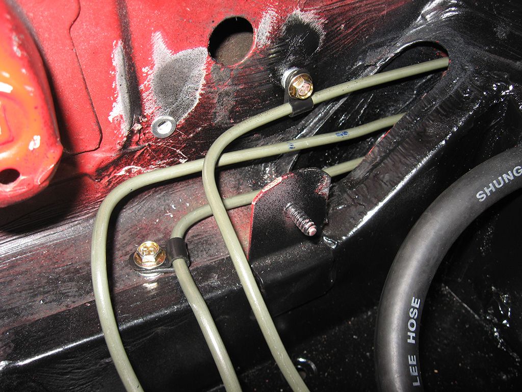
I used some rivnuts or nutserts to provide some mounting holes for the p-clips to fix the brake lines in place and stop them vibrating or rubbing on anything. All that was left to do was fit up the brake lines and brake light pressure switch.
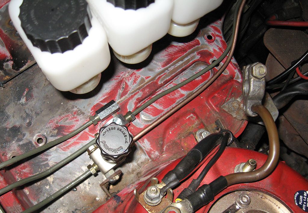
Because the car is RHD, I figured the easiest way to re-route the brake lines was to simply use a t piece for the 2 front brake lines as they were already over on the left hand side of the car where the master cylinder and booster originally was. All I had to do was run a fluid line from the new location of the master cylinder back to a t piece on the left hand side, which would then split to both calipers in the front.
I had removed the rear proportioning valve and located an adjustable one on the right hand side, so I ran a new brake line across for the rear brakes. Everything turned out pretty good and with everything in place, you can barely notice the difference.
This left me with having to relocate the loom to the other side of the car as the ECU was originally tucked under the dash on the right hand side. I thought about getting someone to send me a LHD one and just located it nice and easy, but in the end I thought I would try to lengthen it and relocate it where needed before I went and purchased one from the US.
Anyone wishing to do this, the O2 sensor and coil looms are shielded, so take note it isn't just a simple splice.
Everything lengthened, I just cut through the existing bung in the firewall to pass the ECU loom through.
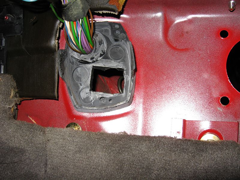
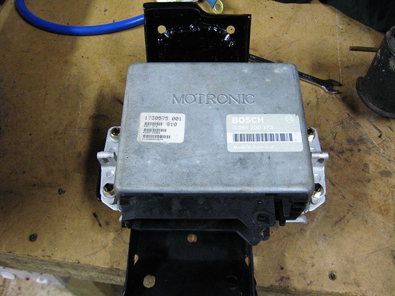
As there is no provision for the ECU to be located on the left side, and seeing as I had a giant hole to fill from the original location of the booster, I thought I would solve both problems by making a new bracket. It filled the hole left by the booster and mounted through the existing points in the firewall and dash, so no hole anywhere on the firewall to be seen.
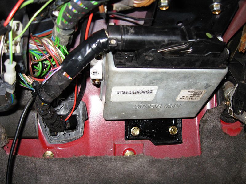
It all works well and the ECU is tucked up above the back of the glovebox. You can't even see it as all the covers fit back in place like it wasn't even there. I'm still not really happy with the length of the loom as I had to loop some of the loom around in the engine bay to take up the slack, but it works. If I was doing this again for a customer I would just pickup a LHD loom I reckon. Make things much neater and a lot easier.
I cut the connector off the original brake light switch and spliced in a new length of cable to run to the new pressure switch. I used some bolts and some P clamps to space out and support the brake lines under the dash as the 2 or 3 type cable clamps are really hard to find here in Australia. Next time I order some stuff from the US ill buy some to neaten them up instead of the bolt method, but it's all neatly tucked away under the dash, which was my goal in the first place.
That was more or less it, I fit up the new big brake kit on the front and bled everything though. Brake feel is amazing now. Pedal is about as firm as the standard one, it's just completely linear in application because you have no support from the brake booster.
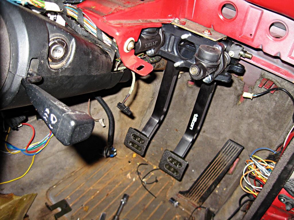
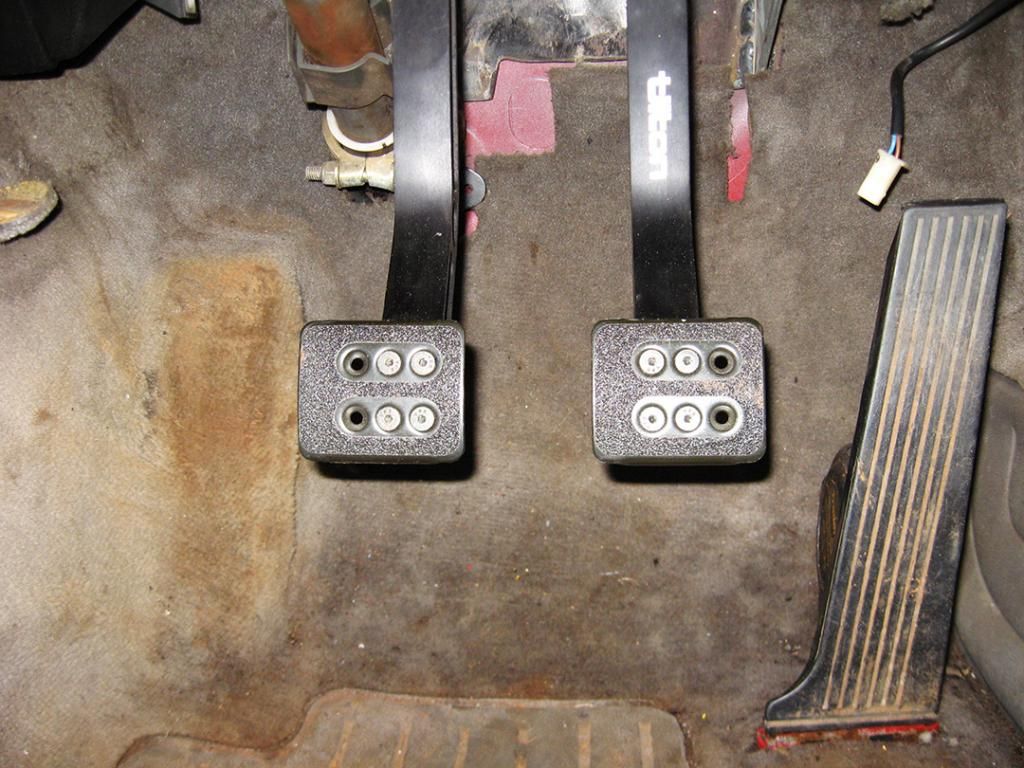
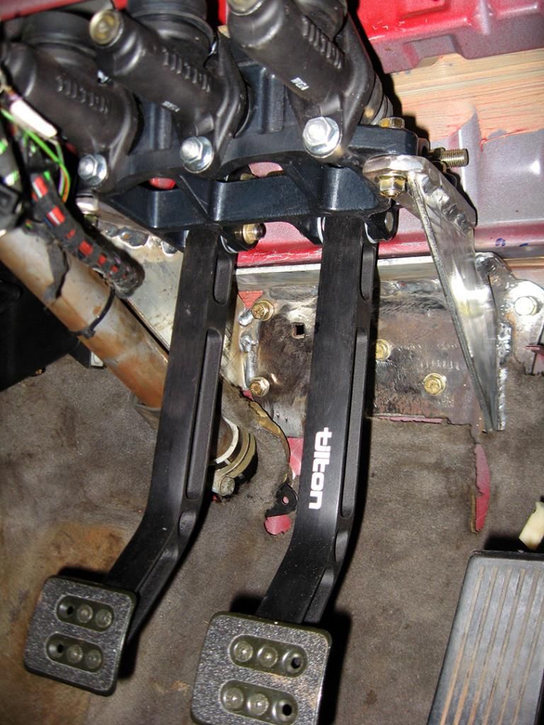
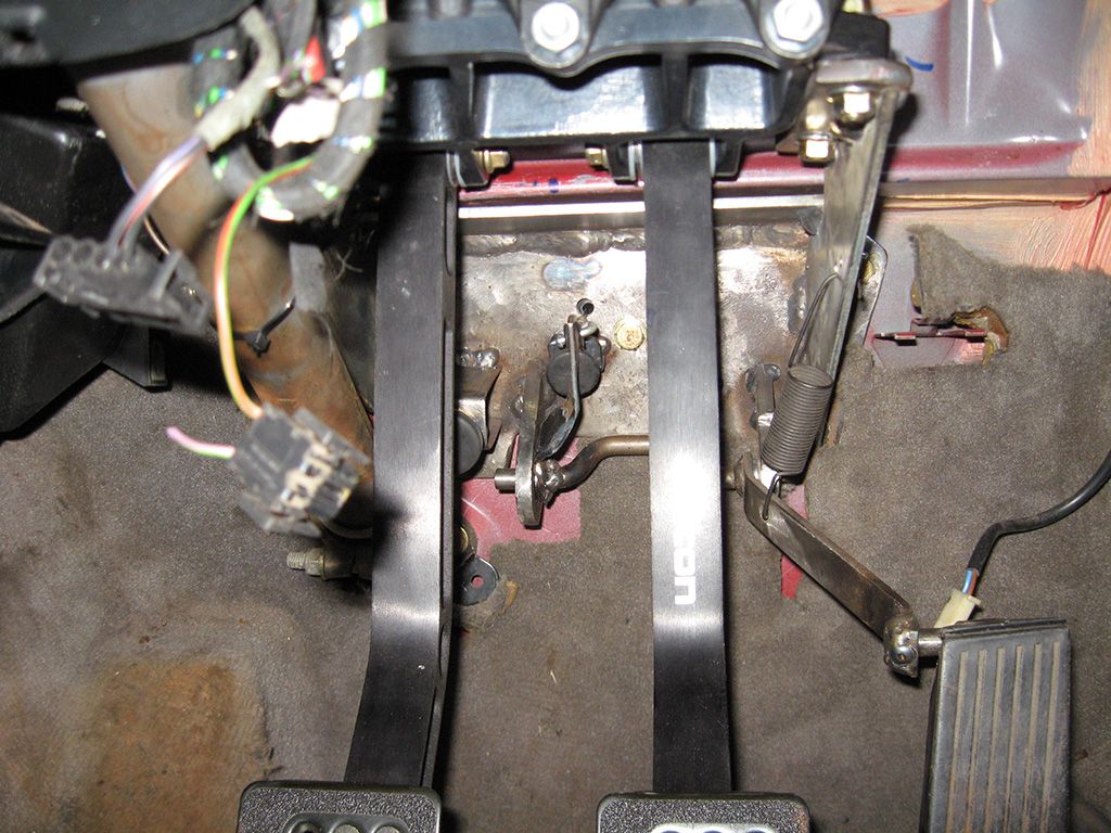
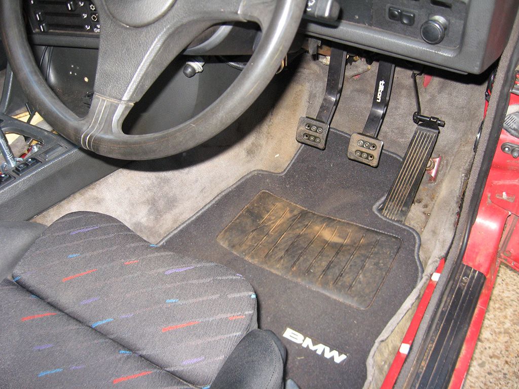
I haven't fit the cable bias adjuster for the pedal box bias yet, I really want to put it in the car, but this is illegal here. So i think ill wait until everything else is finished, everything is completely passed by the engineer, then Ill fit the bias control inside, maybe might hide it inside the center console or something. This is the end result with the positioning of the pedals.
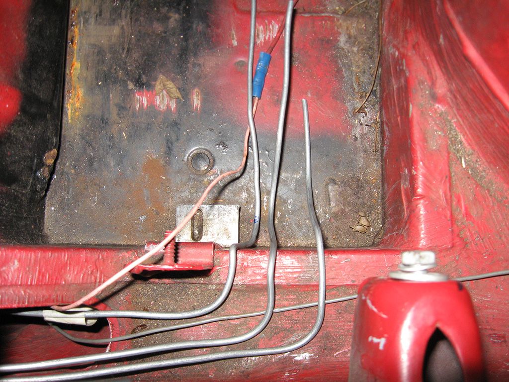
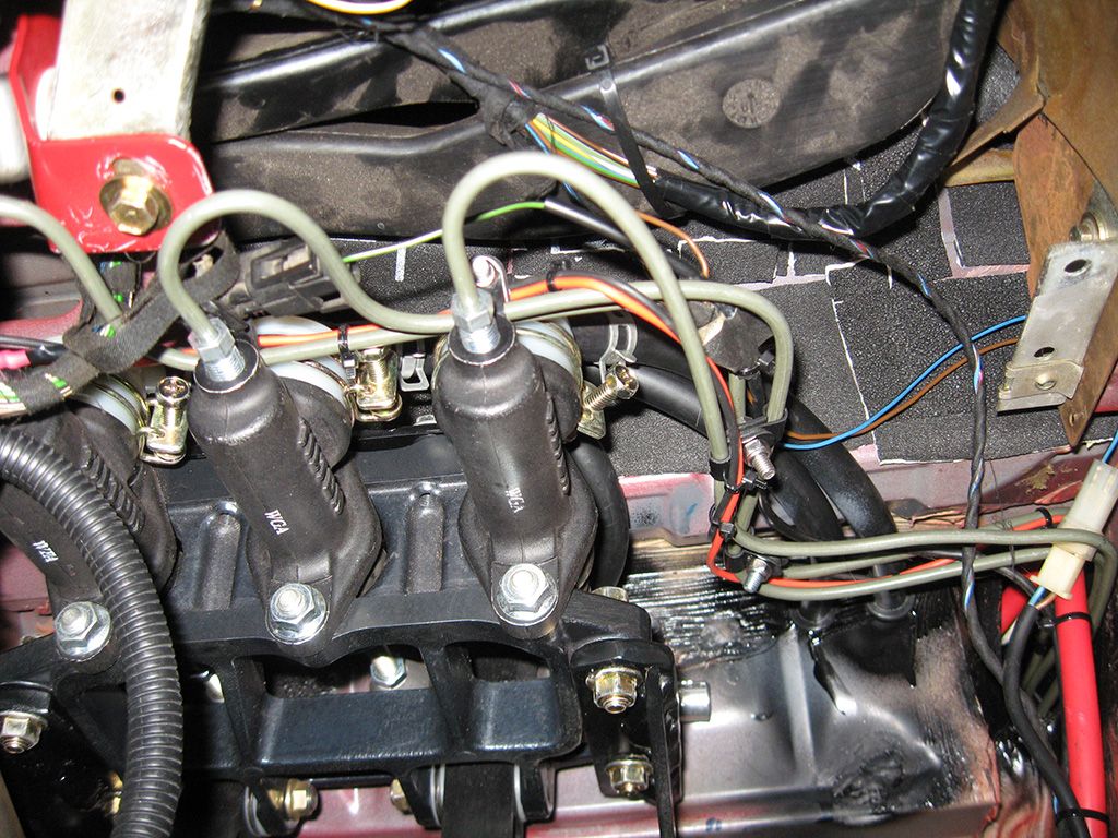
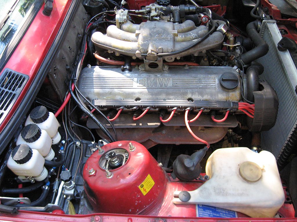
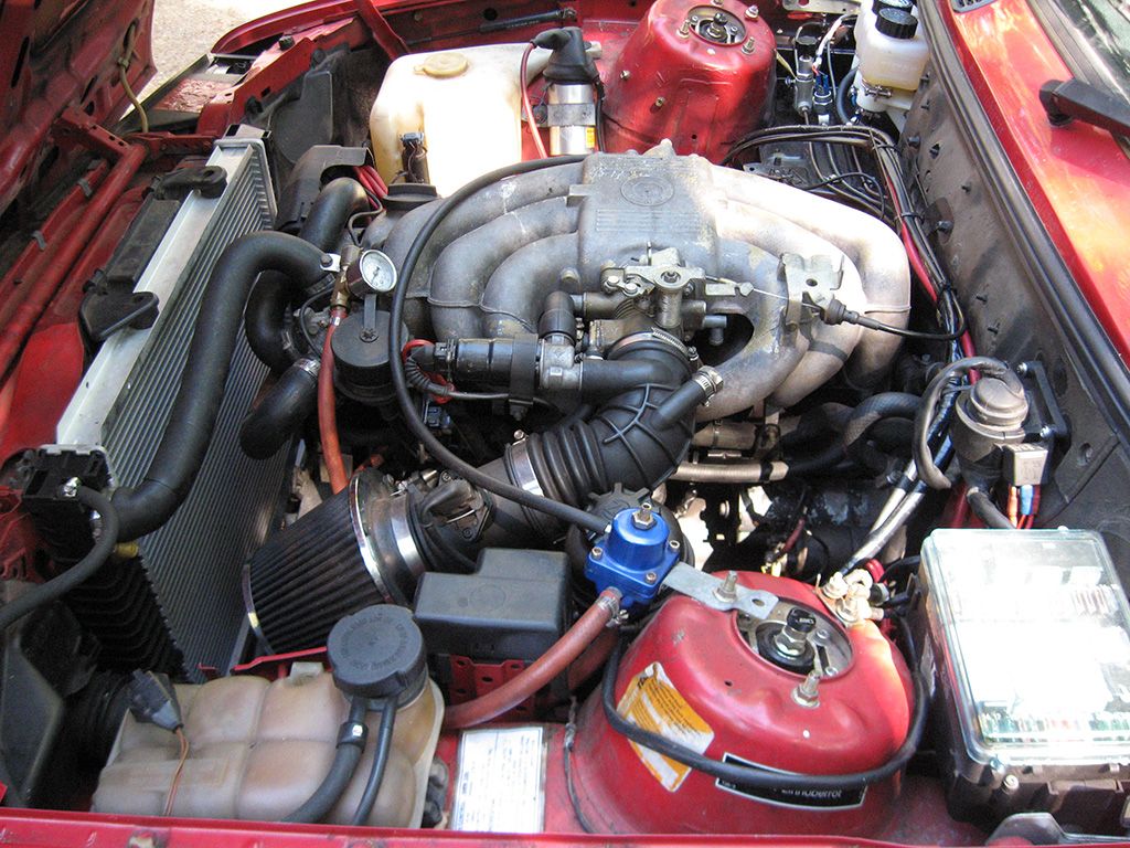
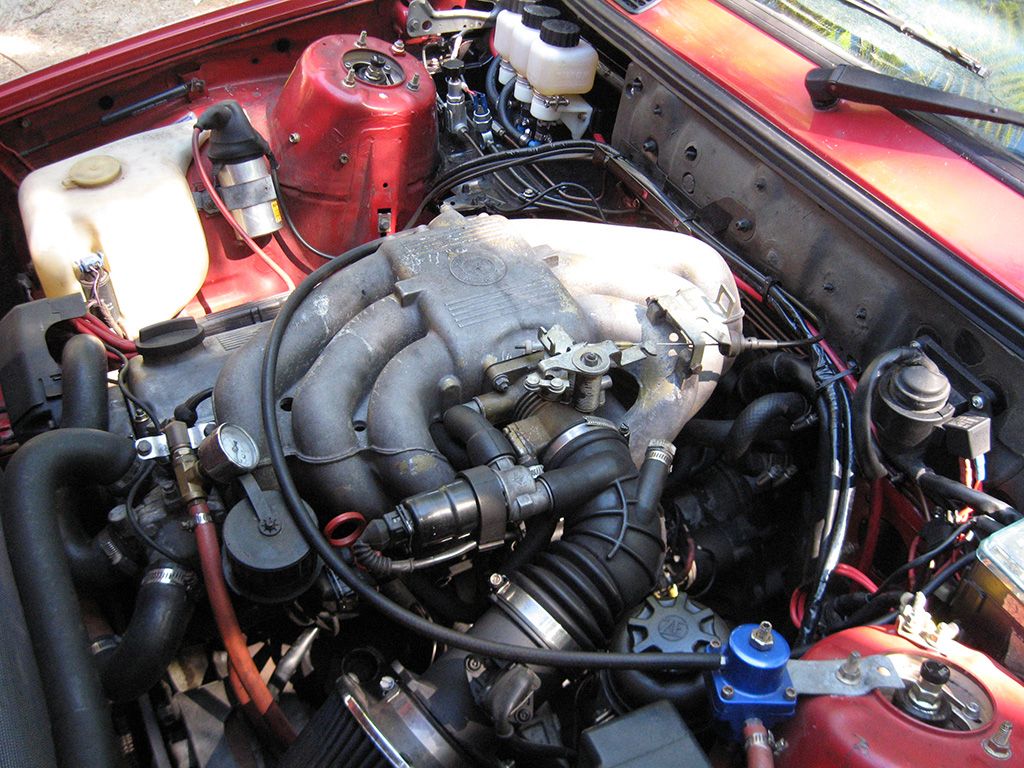
I relocated the earth point to the other side and neatened up a few things in the engine bay. This is the end result in the engine bay now.
Couple of things before I start. We have some strict laws here with regards to modifications. You can't just go chopping into the firewall or welding on it and expect it to be passed by an engineer, meaning your modifications won't be legal which means you cant register/insure/drive your car on the street.
Because of this, in discussions with the engineer who was to approve the mods and plate them (get a little blue plate that mounts in your engine bay that says the vehicle has been mod plated and the modifications have been passed), the only way he would allow such extensive changes without causing issue under the rules would be to try and utilise as many as the factory bmw mounting points as possible. He wouldn't have a problem signing off on it if it looked to use the same mounting points as standard. We had a big discussion about just how strong these points really are, the end result was he pretty much agreed with me, the firewall will flex a hell of a lot (and it already does on the stock pedals), but from a legal stand point it will cause the least amount of trouble if anything is ever inspected.
We talked a little about positioning and how to mount the pedals properly, had a look at some other overhung designs and how he had mounted them previously, decided it was pretty easy to make a mount for the underside of the pedals that is mounted through the firewall and braced through the top of the pedal mounts.
With this in mind, everything was way over spec as far as stiffness and plate thickness. I was using the 6.2:1 longer throw tilton 600 series overhung pedal set (new part # is 72-608 ), no booster and I have huge legs to stamp on the pedals. When coupled with the flex in the firewall everything would be oversized, then when the car is pulled down later on to paint, I was going to remake the pedal box in slightly thinner materials where it could be sacrified (mainly around the bracing and probably 5mm plate for the firewall mount).
I started it all when a package arrived from summitracing. Much head scratching followed.
Brake Setup on the car
Tilton 600 Series Alloy Overhung Pedal Set 6.2:1 Ratio (72-602)
Tilton 75 Series Short Master Cylinders.
-5/8" for front and rear brake master cylinders (75-625U)
-7/8" for clutch master cylinder (75-875U)
**Note** This is really sized to suit the V8 clutch going in later, id recommend running something much smaller around 3/4" or if running with a bmw engine (228/240mm clutch). The pedal is very heavy with the 7/8" cylinder (as I expected it to be).
Wilwood Adjustable Proportioning Valve (260-12627)
Massive Brakes 300x32mm front brake kit.
Wilwood Forged Super lite Caliper, 1.38" pistons (120-11130)
Wilwood BP20 Pads (150-9416K).
It was evident from the beginning that the 6.2:1 ratio pedals were a LOT longer than I had realised and the space in the E30 is a LOT smaller than expected. The challenge was to mount the pedal box as high as possible to maintain plenty of space under the pedals between the floor pan (and providing good contact on the pedals), but the master cylinders couldn't be so high the remote reservoirs wouldn't feed them properly. Not to mention the whole lot had to be tucked under the dash like it was factory as we couldn't go cutting holes in the dash either!
I started by cutting a piece of 4mm plate to mount through the upper mounts on the tilton pedals and the two upper bolt positions for the factory pedal box. This is essentially a brace they recommend you utilise when doing the install, but I started with it to be able to position the pedals where I wanted them.
I basically redrilled this plate a few times to reposition the pedals exactly where I wanted them. The result was good with regards to position, but the angle on the pedals was kind of extreme with the plate flat and provided next to no room under the steering column mount, so I heated it up and tweaked it a little in a vice to tilt the pedals down a little more and gain some space. Once I was satisfied with fitment, I remade this plate with just the pair of mounting holes needed.
I had to notch the side of the steering column mount a little to provide space for the bolt hole.
With that done I took the original pedal box and made a template of the plate that mounts flat to the firewall.
Because of the flex in the firewall, I used some heavy duty 7mm plate for this mount to help spread the load (more bracing to follow later). I cut it out exactly the same shape as the factory pedal box and drilled all the holes to suit. I mounted everything identical and used the same factory high tensile bolts.
The pedals were hung from the top and positioned and I had the mount on the firewall, so i had to start by joining the two up. I took some more of the 7mm plate and cut two rectangle strips 35mm wide to be used as the underside mounts on the tilton pedals. I cut them just long enough to sit past either side of the tilton mounts, so basically visualise them as being like seat rails running down each side. I drilled them per the mount spacings on the spec sheet tilton provided and mounted them to the underside of the pedals with high tensile bolts.
This provided me with a couple of legs to weld down braces to and would basically form the mounts for the pedals. I took out some cardboard and made some templates in the shape of triangles that ran from the plate on the firewall to each of the mounts on the underside of the pedals. The underside of the firewall has a rib that runs along it, so I had to take a notch out of the top side of the down braces to clear. I cut them out of 4mm plate steel and positioned them in place. I had to hand file them a little to get things perfect, but once positioned properly I tacked everything in place.
I then unbolted everything and removed it from the car at which point I started to think a little more about rigidity. I decided I could kill two birds with one stone, cross brace the pedal box itself and provide a third mounting location through the firewall which would pretty much completely eliminate any flex in the pedal box at all. End result was just behind the pedals themselves, I ran another piece of 4mm plate across both sides of the down braces. This tied them together and positioned this plate directly under the rib in the firewall (basically where the battery tray mount is on cars with batteries in the engine bay). I could now use a plate on the outer side of the engine bay to space the load, drill right through the firewall and into the pedal box, and sandwich the whole lot together with high tensile bolts so the whole thing would be completely supported in 3 places.
I was pretty happy with the fitment until I put the box back in the car. It was pretty difficult to get the whole lot back in there, the down brace on the left side came really close to the shaft in the steering column and you kind of had to twist and turn the pedal box to get around it. It pissed me off so much I ended up taking a notch out of the left side so the whole lot could just slide in nice and easily, completely missing the steering column.
I welded everything together in larger stitches. That's why the welds look a little start stop. Basically, dealing with so much heat It would start to distort the plate and throw everything off alignment wise with the holes, so I welded a bit on each plate at a time to keep the heat down to a minimum. Next time I make one for an E30 I will make a template welded to my steel bench so I can mount all the pieces to the bench to hold them solid while welding. Still, I was pretty happy with the end result.
Everything was solid, mounted it all back in the car and had a look at how to deal with the throttle pedal. I intended to run the M20 for awhile, upgrading the rest of the car before swapping the V8 in, so I had to do something about the throttle pedal.
I hate the stupid bush setup of the factory one, just about every E30 I've ever driven has so much play in the throttle it's ridiculous. I decided the best solution was to bearing mount each end of the throttle shaft, replicating its position from the factory pedal box onto the new one I made.
I raided my local parts shop for some bearings with a 10mm ID to suit the shaft. I cut the original throttle linkage off the factory box, shortened it and made some mounts to hold the bearings out of the 7mm plate I had before. They were basically just two rectangles cut on an angle at the bottom to mount the throttle in the same rough position/spacing as the factory.
On the lathe I turned down a couple of rings the same OD as the bearings, giving me something I could weld to the throttle pedal mounts to mount the bearings without transmitting all the heat into the bearings themselves (like if you were to just tack the bearings in place in the mounts). It's basically more like a sleeve mounted in place giving you somewhere to install the bearings. With the mounts in place, I simply pressed the bearings into the rings and slid the throttle linkage into place. The only thing to note is, if you ever want to remove the throttle linkage from the pedal box without cutting, you have to make sure you space the mounts far enough apart so you can slide the throttle pedal linkage out if you need to just like in the factory pedal box. It's simple as the linkage was designed to be supported with clips on either end to stop it moving once in place. It's just a simple process of spacing the linkage out with some washers so if you wish to remove the throttle linkage, you just pop the clips off the end, remove the washers and slide the whole linkage to the side, out of the bearing at one end, then slide it back the other direction out of the bearing on the other side. Pretty simple when you have it in front of you. Of course, I honestly don't ever expect these bearings to wear out and needing to be replaced, so you can pretty much ignore the above if you want.
I drilled some holes in the down brace on the right hand side to play around with the position of the throttle return spring. Because the whole lot was bearing mounted now, i found it pretty much needed no spring tension at all to snap the throttle closed. Originally I took the factory pedal box and measured the length of the spring when the throttle was closed, replicating this on to the new one I had made, but wow... pedal snapped closed with so much force you could hear the butterfly crying in pain inside the throttle body.
Needless to say, drilled a new hole about 10mm closer, relieving the spring tension. End result, the throttle was butter smooth and didn't snap back at you!
All that was left to do was to make some clutch and throttle stops. I simply bent some 2mm plate steel I had into U channel shape to form brackets. Found the size bolt I wished to use as the stop, then drilled through the plate and tacked a nut on the underside. I simply welded the bent bracket to the pedal box, placed another nut on the bolt I used, then screwed the bolt into place. When I had the length right to set the stop, it is a simple case of just tightening the second nut down to the bracket and locking the bolt in place. I epoxied some nice rubber bungs to the heads of the bolts to provide a soft surface for the pedal and throttle linkage to stop against. You can see them in the background to the right in the above photo :)
The only thing left to do was to make a bracket on the firewall side for the plastic bracket/bung/clip/stupid thing the factory throttle cable uses. In the factory pedal box it mounted through the pedal box in a square hole. Because the firewall plate in mine is so thick, that was never going to happen. Again, basically just made a bracket similar to the stops above, but filed one side down so I could slide the clip into place. You could avoid all this by simply taking the factory throttle cable to any cable services place, have them remove the stupid clip off the end and fit a usual pass through fitting, or you could fit any length cable you want for what ever install you are doing. I just did this because I thought it would work fine and decided I would try it first before having the cable modified. It's still in the car today and works flawlessly.
More or less looked like this when finished.
Next up was to start bending the brake lines, fit the remote reservoirs and bolt everything up.
I made my own brake lines as I have a proper vice mounted flaring tool. I decided I would use the existing hole in the side of the firewall (where the AC lines pass through) for the brake hard lines to pass through instead of drilling through the firewall. I took some thick solder (yes, the tin type) and used it as a template for the length of my brake lines.
I decided early on that I was going to mount the reservoirs, the junctions/fittings for the brake and clutch lines, and the bias adjuster in the engine bay where the battery would normally otherwise sit. I had also decided to use a brake light pressure switch as the tilton pedals I used don't have provisions for mounting a brake light pedal switch, meaning you would have to make a bracket to try and replicate the factory switch setup (which blows). Easier solution was to use a VW golf/beetle/porsche 911 3 pin brake light switch. This switch has both NC (normally closed) and NO (normally open) circuits on the same switch. Perfect as BMW use a NC switch, but mount it in reverse, so when the switch is pressed like when the brake pedal is at rest, it is open. When you press the pedal, the switch releases and is now closed, turning on the brake lights. I also wanted to keep as much of the brake and clutch system metric, like the factory M10x1.0mm lines in use, so everything but the fittings on the master cylinders is metric (these are -3AN like the master cylinders)
Making brake lines is kind of easy with the right tools. I cannot overstate how important it is to have a good flaring tool, it honestly makes all the difference. Likewise, decent quality brake tube is great too, some stuff you get is really hard and difficult to bend. The good stuff can be bent fairly easily by hand.
Start by taking your brake line templates and cutting your new brake line tube (3/16") to length with a tube cutter. I use the wheel type that wraps around the tube, if you go slow only increasing the cutting depth by small amounts, I find it gives really nice cuts that only need a very slight dressing before use.
Slide over a new brake nut.
Select the die and position the tube inside.
Tighten down the clamp a little, but leave it slightly loose so the tube can still move inside the die. What you do here is select the flat section on the flaring tool, then pull the lever like you were doing a flare. This positions the die and the tube perfectly in the flaring tool. You then tighten down the clamp completely and release the handle on the flaring tool returning the block back to the normal position. The end result is the tube should be square and sitting perfectly flush with the end of the die, ready to punch out the flare.
Select the proper punch from the block (3/16 OP1 = single bubble flare). Grab the handle and in a nice smooth motion, pull the handle all the way, driving the punch into the tube until you can't pull any further. You'll feel some resistance, but you need to make sure you press it all the way to the end of the die. You need a bit of force to make the flare correctly, but don't go hanging off the handle either.
Release the handle and return the block to the start position, remove the die and have a look at your newly formed flare.
It was at this point I wasn't happy with the -3AN to metric M10x1.0 adapters I had used in the master cylinders. Just too much hanging off the front and kind of messy and bulky, so I ordered some -3AN brake nuts instead and decided that this would be the only part of the lines with different fittings. So I simply swapped the tube nut out, then flared the other end of the tube, so I had a new straight brake line with tube nuts fitted.
I simply bent the tube up to match my templates using a combination of hand tube benders and simply my hands. It's not exactly as perfectly bent as factory made ones, but I think it does the job well enough.
Just remember, if you have tight bends in the start of your lines you need to flare the line and install the tube nuts BEFORE you bend the hard line. You need a good 3 inches of straight pipe to flare them properly, so if you make the bends you'll find the pipe won't fit in the flaring tool.
With the hard lines flared and bent to suit. I made a simple bracket up to mount the remote reservoirs. I originally purchased a nice 3 chamber tilton racing one, but I found I just couldn't mount it high enough to make sure the fluid flowed properly, so I decided to just use the larger remote reservoirs provided in the 75 series master cylinder kit. The mount itself is just flat 2mm steel plate with a bunch of M8x25mm bolts tacked on the underside. This way you don't have to try and get a spanner in behind the bracket when you want to remove them.
To mount the whole lot to the outside of the firewall, I simply made a couple of L shaped brackets up, bolted one on each side of the reservoir bracket above, then welded the L shaped ones to the firewall. To remove the reservoirs on their bracket complete, all you do is remove the nut from both ends and the whole bracket and reservoirs comes off, attached.
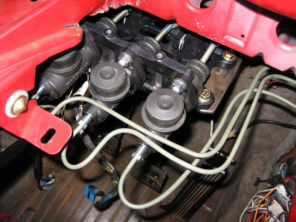
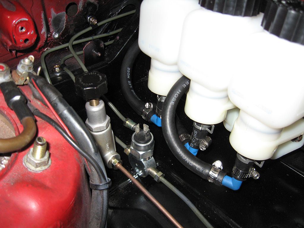
With the whole lot installed.
I made up a simple bracket in the engine bay to bolt the rear proportioning valve to. End result with everything in place.
Next up was to attach the caps to the master cylinders for the remote reservoirs. Simple case of running a little brake fluid around the seal, then pressing the cap down over the master cylinder. They are then fixed in place with a strap type clamp provided in the kit. I worked out where I wanted to position the fluid lines for the reservoirs and drilled some holes through the firewall to locate them. I slide a rubber grommet over the fluid line to protect it from rubbing through the firewall and passed them inside to the master cylinders.
I used some rivnuts or nutserts to provide some mounting holes for the p-clips to fix the brake lines in place and stop them vibrating or rubbing on anything. All that was left to do was fit up the brake lines and brake light pressure switch.
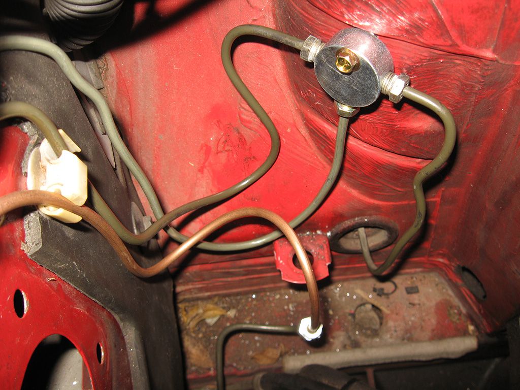
Because the car is RHD, I figured the easiest way to re-route the brake lines was to simply use a t piece for the 2 front brake lines as they were already over on the left hand side of the car where the master cylinder and booster originally was. All I had to do was run a fluid line from the new location of the master cylinder back to a t piece on the left hand side, which would then split to both calipers in the front.
I had removed the rear proportioning valve and located an adjustable one on the right hand side, so I ran a new brake line across for the rear brakes. Everything turned out pretty good and with everything in place, you can barely notice the difference.
This left me with having to relocate the loom to the other side of the car as the ECU was originally tucked under the dash on the right hand side. I thought about getting someone to send me a LHD one and just located it nice and easy, but in the end I thought I would try to lengthen it and relocate it where needed before I went and purchased one from the US.
Anyone wishing to do this, the O2 sensor and coil looms are shielded, so take note it isn't just a simple splice.
Everything lengthened, I just cut through the existing bung in the firewall to pass the ECU loom through.
As there is no provision for the ECU to be located on the left side, and seeing as I had a giant hole to fill from the original location of the booster, I thought I would solve both problems by making a new bracket. It filled the hole left by the booster and mounted through the existing points in the firewall and dash, so no hole anywhere on the firewall to be seen.
It all works well and the ECU is tucked up above the back of the glovebox. You can't even see it as all the covers fit back in place like it wasn't even there. I'm still not really happy with the length of the loom as I had to loop some of the loom around in the engine bay to take up the slack, but it works. If I was doing this again for a customer I would just pickup a LHD loom I reckon. Make things much neater and a lot easier.
I cut the connector off the original brake light switch and spliced in a new length of cable to run to the new pressure switch. I used some bolts and some P clamps to space out and support the brake lines under the dash as the 2 or 3 type cable clamps are really hard to find here in Australia. Next time I order some stuff from the US ill buy some to neaten them up instead of the bolt method, but it's all neatly tucked away under the dash, which was my goal in the first place.
That was more or less it, I fit up the new big brake kit on the front and bled everything though. Brake feel is amazing now. Pedal is about as firm as the standard one, it's just completely linear in application because you have no support from the brake booster.
I haven't fit the cable bias adjuster for the pedal box bias yet, I really want to put it in the car, but this is illegal here. So i think ill wait until everything else is finished, everything is completely passed by the engineer, then Ill fit the bias control inside, maybe might hide it inside the center console or something. This is the end result with the positioning of the pedals.
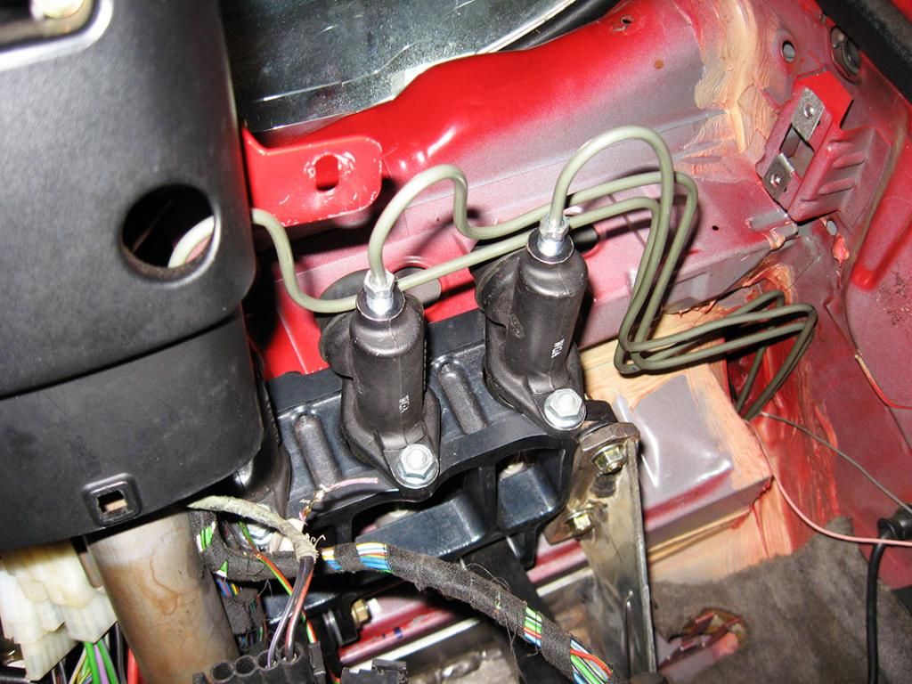
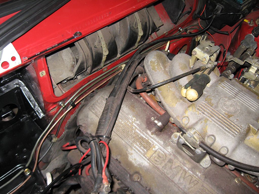
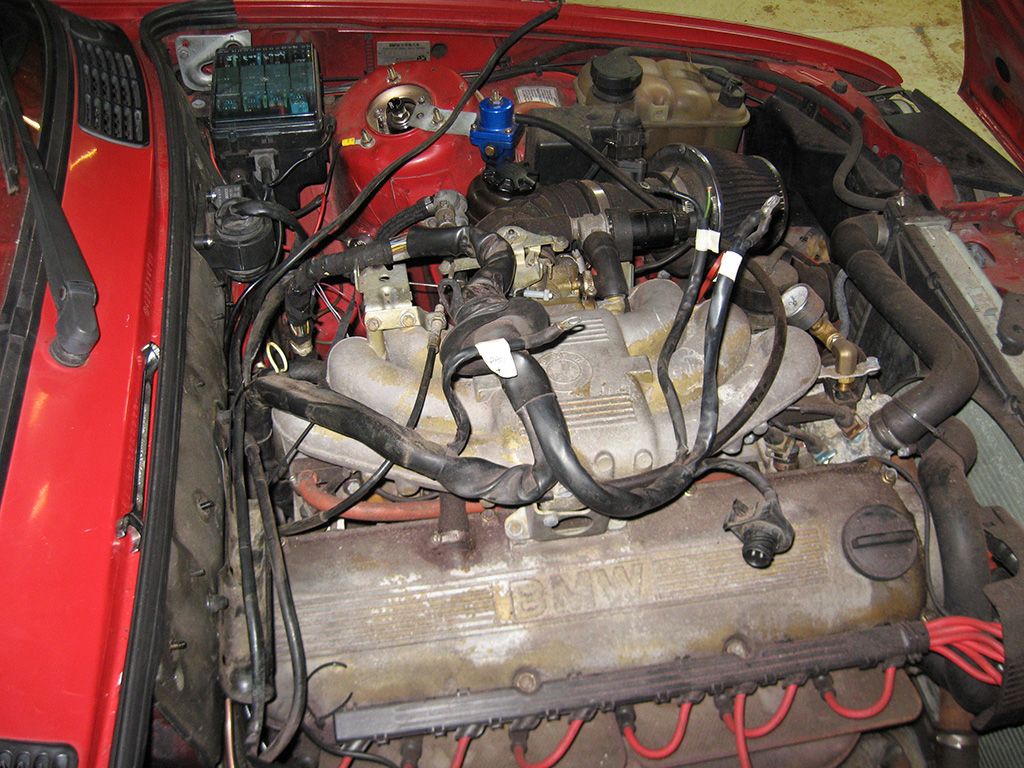
I relocated the earth point to the other side and neatened up a few things in the engine bay. This is the end result in the engine bay now.


Comment