

I was just under the car installing new 02 in addition to new bmp chip and have a small wiring discrepancy. The 4wire o2 has a red, yellow, black and white while the connector is green, brown, yellow, black. I had a similar question before and found that green is power, brown is heater, yellow is signal and black is ground. On the sensor though I think the corresponding colors are black is ground (obviously), yellow signal, white heater and red power? Originally I was thinking white would be power similar to a two wire or any generic circuit but after looking at more info was persuaded otherwise. Can anyone confirm whether white or red is in fact the power supply, I could just get up and test it with the volt meter but just realized it is no longer here with me. Appreciate the quick insight as usual...
-
-
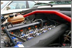
what year and model 02 sensor? As I'll look up the diagram in the ETM85 325e 2.7 ITB'd stroker
-
here you go

Green wire=Power for the heater element(pin 4 on sensor)
Brown=Heater Ground(Pin 3 on sensor)
Yellow=Single output to ECU(pin 2 on sensor)
Black=Sensor ground(pin 1 on sensor)85 325e 2.7 ITB'd stroker
Comment
-
On the 4 pin male connector I have a red, yellow, white and black; can I assume Red is heater ground, yellow signal, white power, black ground...? That is the main problem, resolving the red/yellow/white combo. thanks again for the help,
-HunterComment

Comment