-
Oh wow. Carbs are rather expensive ($1300-$1600 for three). MS2 is waaaaaay cheaper. Carbs schmarbs... -
Thanks man.
An idea crossed my mind this morning a few days after someone mentioned carbs. Triple deuces. That's old school muscle style. Idk, nothing is set in stone...Leave a comment:
-
Lookin good! You got the right clearance on the distributor cap to the radiatorLeave a comment:
-
Mmmk, so I tried to stick the head on to check clearances. Turns out I needed to smack my firewall some more. So I slapped that bitch around some and set my head on with 1mm of space between the head and firewall. Then sorta temporary-like added the old school manifold. There may be some clearance related riggery needed. The hood will be getting a "vent" of some degree later on for the "shotgun intake scoop". I haven't tried it with the original intake manifold. I bet it's a little lower profile.


Leave a comment:
-
I did end up needing to twist the shift rod ever so slightly to get the shifter to be perfectly centered. Probably about 3 degrees of twist. T'was easy though, vise and a pipe wrench.Leave a comment:
-
I did get one pic, but a bit blurry. It was super easy. I just cut 3 5/8" off of the transmission end (front) of it and drilled two new holes for mounting it back (g240). No welding at all. I believe i just got lucky on the style of carrier. Here it is just before I cut it. But I just replicated the two holes after I cut. Then it was done.

Leave a comment:
-
Looking good! I really wish you had pictures of the carrier. I have some ideas of how I will do mine once I position the engine and figure out how much to cut out, but I always like seeing other people's approaches.Leave a comment:
-
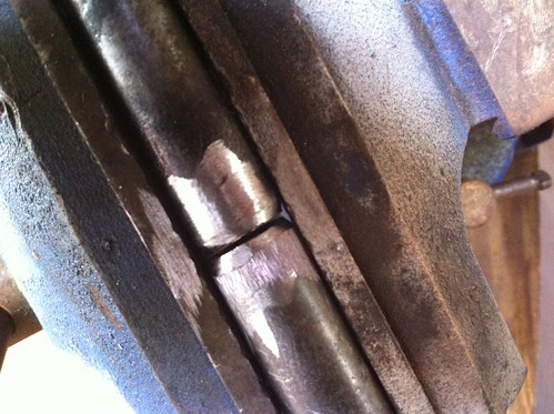
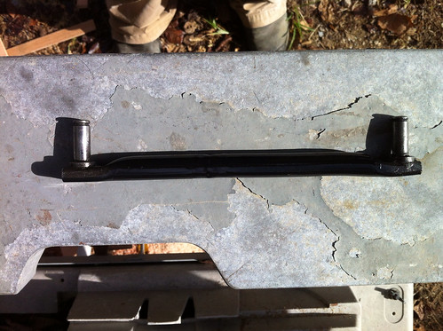
A little shifter rod shortening. Cut out 3 5/8", ground the cut ends and welded them back together.
I also cut off the shifter carrier and drilled two new holes for mounting it to the transmission (sorry no pics). It literally took about 3 minutes. I then added a small bit of angle iron to mount the back of the shifter carrier to the chassis.

Closer...
Fin
Shifter assembly is in and adjusted nicely. No binding, smooth action.Leave a comment:
-
Yea make sure you put you replace your cap and rotor before putting the rad in other wise it makes for a pita to get it in and outLeave a comment:
-
Nope. That shit is all done now. If the distributor cap doesn't fit, I'll just be forced to go wasted spark. Honestly, I think I'm in at least position 2.5, maybe even 3. I believe it will fit, but I didn't want to go any further back so as to not have to shorten the driveshaft.
I'm currently in a battle in my head of wether to go n/a at first, or just go for the whole shebang and slap a supercharger on it right off the bat. If I do forced first, I'll be doing another MS2 so wasted spark won't be too big of a deal.
Irrrrregardless, I just got the shift linkage all fixed up and it's titties. Round, firm, yet still bouncy, titties.Leave a comment:
-
Generally the tightest clearance is the dist cap to radiator clearance, have you/are you going to mock up a head with cap and mount your radiator to check clearance before you modify shift linkage, finalize engine mounts, etc to fit at the current engine position?Leave a comment:
-
Leave a comment:
-
-
Your mounts look like 1/4 inch steel to me which is pretty damn stout. I agree with vertical (torque) load being the strongest force to deal with and if they do bend they would probably spread in the middle and bow into the shape of a vagina. The vagina shape has nothing to do with you as a person or your mount design.
If i were to reinforce those mounts, i would weld in a horizontal in between the two long sections but in the middle vertically thus creating an I beam shape (sideways) which would keep the (beefy) verticals tied together. It would not need to be thick (1/8th inch?) or full length so bolt access would still be good.
Props for making your own mounts, keep it up !Leave a comment:
-
If you could hold one of these mounts, you'd see where my confidence comes from. I'm of the school of "make it. if it breaks, fix it.". Here's what I'm gonna do. I'm gonna leave it like it is. If it cracks or bends, I'll deal with it then. I would bet large amounts of money that the whole car could easily hang from these mounts. The part that would break first would be the 1 little 3/8" bolt that holds the motor to the subframe on each side. You see, it just doesn't make sense to make the combined strength of these mounts (in the front to back axis, which is how boxing the top and bottom would strengthen them) stronger than those two 3/8" grade 12 bolts that hold it in. Now, it does make sense to make them very strong in the up to down axis because of bumps and shit that make the motor "heavier" than it actually is. Boxing the top and bottom would do little for strength in this direction. Plus I need to be able to get to the bolts that hold them to the block.
In short, if they break, I'll admit it, and you can say "Told ya so!". And thanks for caring about a total strangers' build.Leave a comment:

Leave a comment: