Announcement

Collapse
No announcement yet.

My '75 2002 Sleeper

Collapse
X
 
  • Filter
  • Time
  • Show
Clear All
new posts

  • tinkwithanr
    replied
    So as I alluded to earlier, I decided to deleted the stock pedal assembly and replace it with a Tilton floor mount assembly. There were a number of reasons I decided to do this. First, the itb setup meant that the stock brake booster wouldn't fit anymore. Likewise, with the G260 trans in place, the stock throttle linkage would be very close to the outer bell housing. By switching to the Tilton setup I am able to avoid those issues.

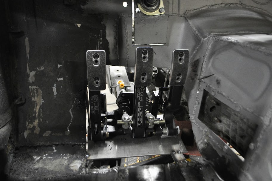
    The pedals in question are are Tilton 72-603, which is a three pedal assembly. The brake pedal uses a balance bar, which lets you adjust the bias front to rear from the driver seat (with the optional cable adjuster). It also keeps the front and rear brakes on separate master cylinders, so if one of the circuits ended up getting damaged I will still have brakes to help bring the car to a stop.


    If you look at the above picture, you'll notice that the pedal pads are also adjustable. There are 4 vertical positions and three horizontal, for a total of 12 per pedal. I am also thinking of machining a new gas pedal pad to help with heel-toe driving. I'll wait until I can try it out before going down that road though.


    In the next picture you can see the throttle linkage assembly. The linkage, like the rest of the pedal assembly, is completely adjustable. This will allow me to dial in the throttle plate position relative to the gas pedal, avoiding a laggy or on-off feeling.


    Of course the new pedal assembly isn't without it's issues. Mainly the fact that the driver side frame rail goes right through the same area, so it needs to be cut out and rerouted. Also the clutch master cylinder is much further off to the right than the old setup, so much so that it sticks into the driver side footwell. If it end up interfering with the steering at full lock I'll need to make up a simple linkage that moves the clutch master cylinder up and over, away from the wheel/tire. I'll wait to make that decision until the front suspension is back in though.


    Here is the pedal assembly bolted in place:


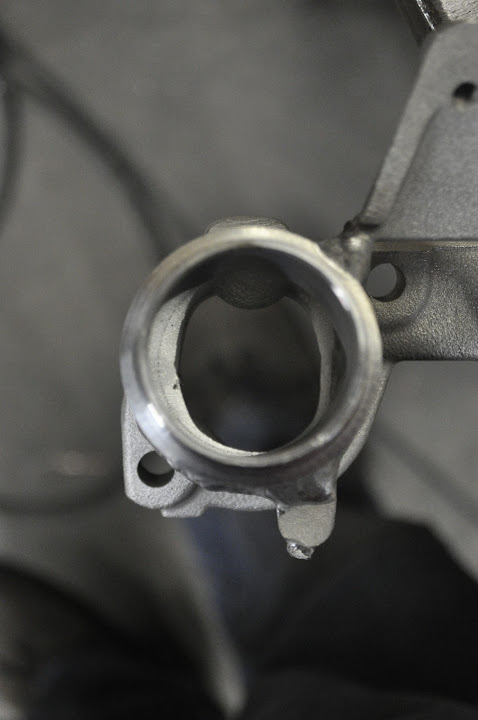
    Here you can see clutch cylinder, it sticks into the wheel well an inch or so.


    And here you can see how much of the frame rail/firewall needed to be trimmed out. The frame rail will be remade with 1/8" or 3/16" steel boxed and welded flush much like the motor mounts, but out of the way of the brake and clutch cylinders.


    I also picked up a new tool to help strip the old tar and POR-15 off the floor boards so I can make sure they are clean and rust free.


    And the progress after ~15 seconds of grinding:


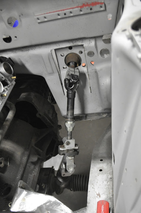
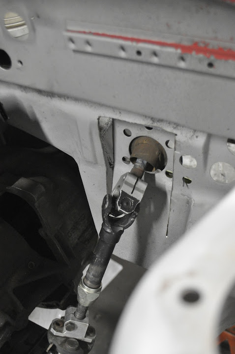
    Then I got the steering column support bearing tacked in place. Ironically it fit in the stock location of the old column mount, it just needed to be angle downward slightly.


    Then I took a break from work and took a few pictures with my other '02. Once I get Fiona finished I want to paint this one as a 'mini-me' and it in her glovebox or center console area lol.


    Thanks for looking!

    Leave a comment:


  • craiggroves91
    replied
    Originally posted by tinkwithanr View Post
    Yup, I just threw the trans on there for making up the engine and trans mounts.
    Got it, just trying to look out for you!

    Great work

    Love seeing your updates

    Leave a comment:


  • tinkwithanr
    replied
    Originally posted by MazterDizazter View Post
    *whew* just made it through all 23 pages. That was 1.5hrs well spent! I'm absolutely floored by this project. I envy your fab skills and creativity greatly! I will say I was a little worried by how scatter-brained the project seemed to start out as (looks like the way I approach a project - trying to do everything at once - which means it never gets done) but once you got the chassis media blasted and fixed all the rust the project started to really take shape. I can't wait to see the finished product - best of luck!
    Thanks! I can see how it seems pretty all over the place, but keep in mind that most of this has been going on for the past two years, so it's been fairly spread out with a lot of thinking and planning (good and bad) in between. Crazy to think of where she started and where she will end up.


    Originally posted by N2MYE30 View Post
    I dig the pedals but what really caught my eye was the peep window for the slave cylinder...haha...very cool.
    I figure if I put it in there I'll never need to bleed it lol.

    Leave a comment:


  • N2MYE30
    replied
    I dig the pedals but what really caught my eye was the peep window for the slave cylinder...haha...very cool.

    Leave a comment:


  • MazterDizazter
    replied
    *whew* just made it through all 23 pages. That was 1.5hrs well spent! I'm absolutely floored by this project. I envy your fab skills and creativity greatly! I will say I was a little worried by how scatter-brained the project seemed to start out as (looks like the way I approach a project - trying to do everything at once - which means it never gets done) but once you got the chassis media blasted and fixed all the rust the project started to really take shape. I can't wait to see the finished product - best of luck!

    Leave a comment:


  • tinkwithanr
    replied
    Quick Teaser:


    This mod is not for the faint of heart.


    Leave a comment:


  • tinkwithanr
    replied
    Yup, I just threw the trans on there for making up the engine and trans mounts.

    Leave a comment:


  • Roysneon
    replied
    Quite sure that's his mock up engine.

    Leave a comment:


  • craiggroves91
    replied
    Originally posted by tinkwithanr View Post


    Looks like you're missing the plate that goes in between the engine block and trans?

    Leave a comment:


  • semaj4712
    replied
    I want to be just like u!!!

    Leave a comment:


  • red_e30
    replied
    Nice

    Leave a comment:


  • tinkwithanr
    replied
    Small update from today. Didn't have a lot of time to put into her but I managed to get the steering linkage figured out. I only have pictures of the 'finished' product (I use that term loosely), but I basically just took the stock E30 linkage from my parts car and shorted all the sections of it so that the universal joints were closer together. Then I shortened the stock steering column.


    I also needed to notch the firewall a bit so that the angle between the sections was small enough that the universal joints wouldn't bind. The lower one was fine, but the upper joint was very close.


    I also need to add another support bearing to the middle section of the linkage. In the stock setup, the steering column didn't have any universal joints, it just ran straight to the steering box. Because of that the stock '02 steering column only has one point of support for the shaft itself. But now with the extra joint in the linkage the shaft has a bit of play, which the extra support bearing will take care of.

    Leave a comment:


  • A Sucked Orange
    replied
    :hitler:

    Leave a comment:


  • tinkwithanr
    replied
    I decided to clean up the throttle bodies since they were pretty dirty when I got them. Can you guess which one is which??


    5 more throttle later:


    Here's a close up of the extensions I welded on the linkage tabs. Works great.


    Then I worked on blending the modified intake manifold. This is how it looked when I started:


    And after a couple minutes with a die grinder it changed to this:


    And here is the same port with my spare gutted throttle body in place. I'm very happy with the overall taper and size, though I still need to fine tune a couple of areas. But I'm going to wait to finish them until I match the manifold to the head, which still needs to be ported as well.


    And here they are bolted in place in the engine bay. The nice thing with this setup is it doesn't get in the way of the stock fuel rail, pressure regulator, and thermostat housing. My original S54 setup had some clearance issues:


    Then I had to reposition the dipstick tube. If you look at the above pictures, you can see the stock position puts it right between the first and second cylinder ports. With my plans for a plenum this would definitely get in the way. Luckily my largest bead roller die was the perfect diameter to the dipstick tube, so I was able to avoid pinching the tube at the bends. After a few carefully placed bends this is what I ended up with.


    This new position should sit right between the intake plenum and the upper radiator hose.


    Thanks for looking!

    Leave a comment:


  • tinkwithanr
    replied
    They are 38mm. I just finished porting the manifold, and it seemed to blend very well overall. The other huge plus is 1.5" ~ 38mm, so I could use standard tubing sizes for the runners and plenum parts.

    Leave a comment:

Working...
X