-
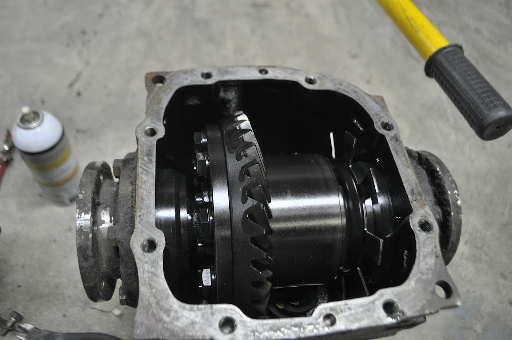
More progress from this morning. Since I was starting to mock up the e30 rear subframe, I figured I should mount the diff I'm actually planning on using as well as the e36 dual eared diff cover. First up was to inspect my 3.25lsd. It's a rebuilt unit from BMW, denoted by the 'SE' tagged on the side of it. Getting the cover off, it's probably the cleanest diff I've ever gotten my hands on. All the gears are immaculate and not even any discoloration from old oil. I was thinking of replacing the seals before putting it on the road, but now I doubt I'll need to.
The ring gear, lsd pumpkin and speed sensor:
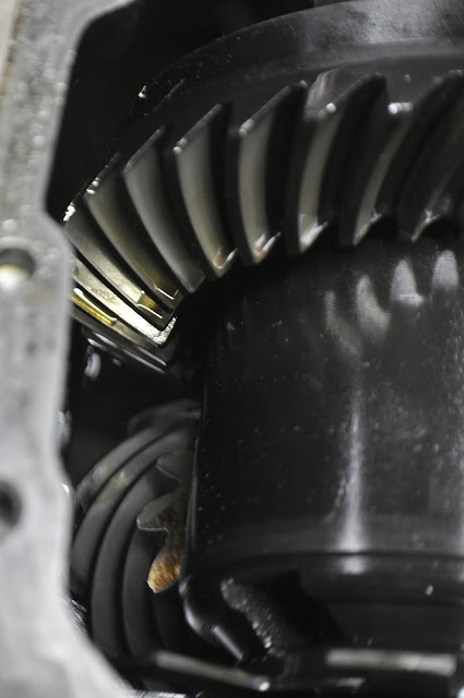
Ring and Pinion:
Next up was to install the e36 diff cover onto the 3.25 lsd. The main issue with this setup is the e30 reluctor ring is larger than the e36 counter part (or at least closer to the diff cover). This causes it to hit the cover and sensor. First you need to relieve the inside of the cover a bit to clear the ring.

With the cover clearanced, next up was making a spacer to move the speed sensor 0.300" out. This would let it get the proper reading from the ring while not interfering with it. So I took some measurements and made a quick sketch:

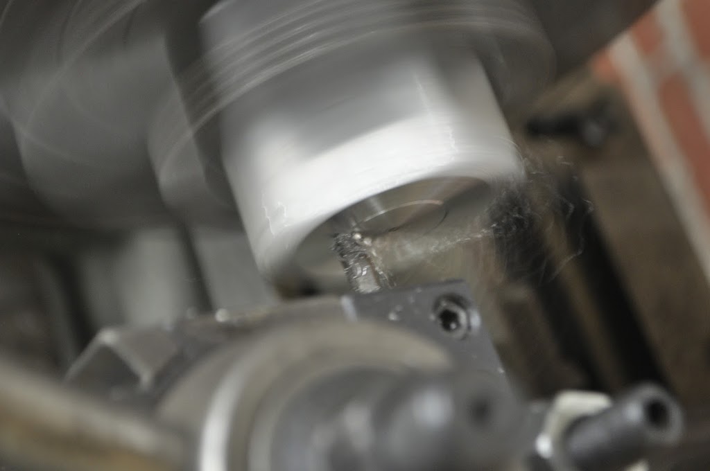
And of course I was out of 1.5" 6061 round stock, and I wasn't about to turn down my 4" 2024 round stock for a little sensor spacer. Luckily I did have some 1.5" square stock, so I cut off a section to turn down.

Facing the saw cut edge:
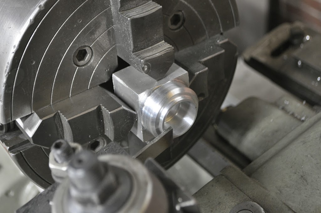
The diff cover side finished:

Inner diameter bored and lining up the cutoff tool:
This is how everything lines up. I may need to get a slightly larger o-ring for the spacer-diff cover seal, but overall it fits together pretty snug:

Installed view from the outside. As it sits right now it just bolts down with the stock metal bracket, which bends now that it's spaced up off the cover. I'm going to order some 0.5" round stock 6061 to make two addition small spacers to help support that connection:
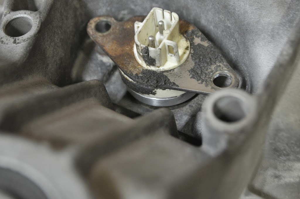
Inside view with everything installed. You can see the extra clearance that the sensor has now:

Diff cover and sensor bolted up to the 3.25lsd:
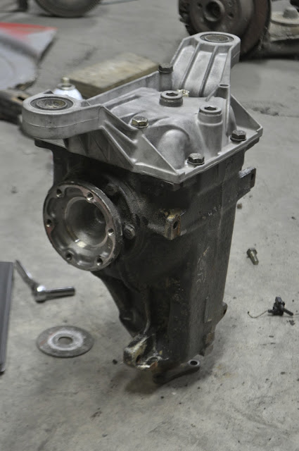
3.25lsd bolted up to the subframe:

And finally the subframe back under the car, ready for mount fabrication:

Thanks for looking!Leave a comment:
-
More progress from the night. First up was to start work on the trunk repairs. The rear mount for the rotisserie was being supported by the old shock mounts, which are part of the trunk floor, so I had to set her back down on jack stands before I could get to it.
One on the ground I removed the stock bumper retainers. There was a lot of crap and gunk holding them in so I had to persuade them with a few blows of my mallet.

With the bumper retainers out of the way I could start cutting out the old, rusted trunk floor. First were the side braces, which are only found on the late model 2002's (square tail). I won't be adding them back in, but only because I plan to run two diagonal sections of tubing down from the shock towers to the rear corners.

Next under the knife was the passenger side floor, which used to be the mount for the gas tank. Also missing from the picture is the center divider, which looked solid from the top but was completely rusted out on the bottom.

Then the old spair tire well was cut out. I haven't decided if I'm going to replace it with another tire well or just not have a spare in the car. It really depends if I end up centering the fuel cell in the trunk, which would let me move it a bit further inboard, or leave it more off to the side like the stock location.

With the rear trunk floor gone, I started trimming for the e30 rear subframe mock-up. I plan to frame out the trunk with 2"x2" 1/8" wall tubing, with the front most crossbar being in line with the ear mounts of the diff. Because of this I need to get the subframe position figured out before I can finish the trunk and mount the fuel cell.

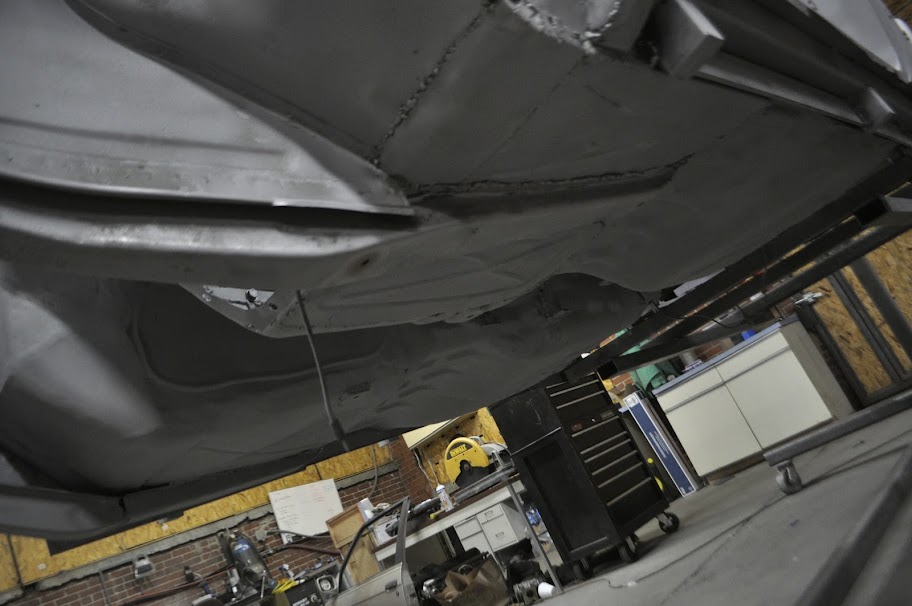
View from underneath:

Lifting the rear subframe into position:

Hub positioned in the wheel well:

Wheel mounted:

View of the subframe from the front, looking through the engine bay. And yes, the differential input shaft is off-center with respect to the center of the subframe. From this view the centerline is based on the opening in the subframe, which appears dead-nuts on.

Yay extra track width!! It's to bad my wheels don't fit the fenders anymore.....

The band aid in place:

Muuuch better, that being said I will be getting wider wheels/tires. Shooting for at least 15x8 and 225's, but would prefer 245 if I can find the right sidewall.

As far as permanently mounting the subframe, I have two options. One is to modify the e30 subframe to use the stock '02 mounting points. This has the benefit of utilizing the body reinforcements that are already there. I also wouldn't have to fabricate any forward mounts, only the differential ears. The other option is to keep the e30 subframe stock and move the mounting points on the body. This would be nice because it would allow me to bolt up any e30 subframe, if the original one were to get rusty or bent. The downside is I would need to engineer new mounting points and ensure that they are heavily reinforced.
After getting the e30 subframe up there, right now I'm leaning towards the second option. The e30 bushings are roughly 2 inches wider and 1 inch forward of the '02 counterparts. This puts the outer trailing arm mounts right up against the stock subframe mounts on the body. I'm also not convinced that my stock mounting locations are in very good condition. While making new mounting points will be a challenge, it will give me a chance to tie them into the cage structure as well as the unibody. This should give enough integrity to withstand any power levels I throw at it.Leave a comment:
-
Thanks guys!
Never say never, I didn't think I'd be doing this two years ago either. Just take the opportunities that come to you and run with them.
You and me both!Leave a comment:
-
I think it's just so awesome to see old 2002's getting rusty parts replaced with new metal.Leave a comment:
-
Great work.
I wish I had the room, tools and welding skills to attempt the work you have done.Leave a comment:
-
Impressive is going to be understating the level of your project a bit!Leave a comment:
-
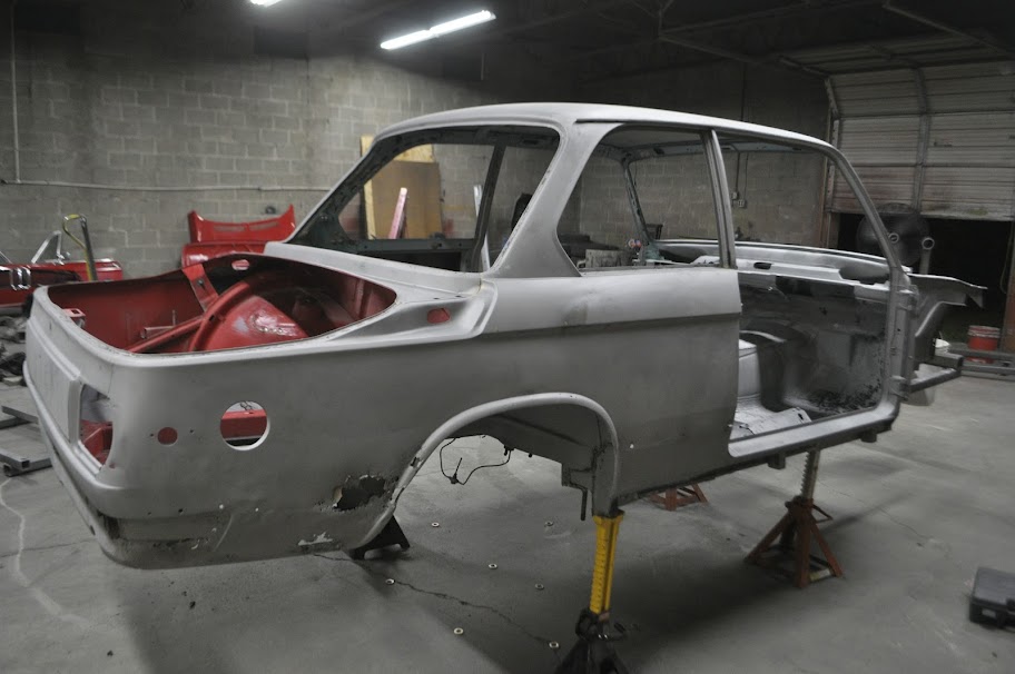
Finally finished with the media blasting. This past week I finished hitting the rest of the underbody as well as some of the interior. I did skip over some parts of the interior, but they will just take a little bit of work with a angle grinder and stripping pad to get down to where they need to be.
The Results:


Overall I'm pretty happy with the results, although I can definitely say that I will gladly pay someone to do that the next time. Next will be fixing up the rust spots and fabrication that needs to be done so that I can lay down the epoxy primer. That should keep the body from rusting away until I can get the interior, engine and suspension sorted out.
Thanks for looking!Leave a comment:
-
Sir Kudos for you for your own fabrication and you have just inspired someone else to fix their cars by themselvesLeave a comment:
-
Good guesses. The correct answer is.... Tubing Bender!!
After not finding a good used one locally and not wanting to pay out the a$$ for something I will only be using to make one roll-cage for, I decided to make one following a set of plans I found online (Also known as the Go Trikes Bender). A few key elements that I really like about this bender in particular is the vertical bending angle lets you easily measure your bending angle as you go. Another plus is you don't need to support the far end of the tube on larger pieces, like you would with a horizontal bending position. It also runs off a pneumatically controlled hydraulic cylinder, so there's no need to bolt it to the floor or use a huge breaker bar like you would on most cheap, manual benders. All in all I have about $100 in parts (not counting the dies). Not to shabby considering it's only two days of my time, and it's something I enjoyed making.
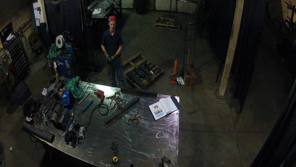
This also gave me another chance to use the GoPro for a timelapse movie. I think the stationary camera position makes the video much easier to watch. FYI, there's no audio on this video. I got lazy and didn't feel like finding a good song lol. Oh, and you'll notice that the video stops before it's fully assembled. That's because the battery ran out lol. Looks like I may need to get the extended battery pack or remember to plug it in before shooting.
And here are some pictures of it mostly assembled. I still need to paint it, but I'll get that done here in the next week or so.
Retracted Position:
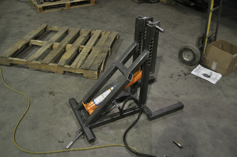
Fully Extended Position:

Leave a comment:
-
Soooo close, I'll go ahead and say you got it right lol. Technically it's a tubing bender (yup there is a difference) but it's really just splitting hairs at that point.
Congrads! You get a big Thumps Up! :up:
Thanks!Leave a comment:


Leave a comment: