Announcement

Collapse
No announcement yet.

My '75 2002 Sleeper

Collapse
X
 
  • Filter
  • Time
  • Show
Clear All
new posts

  • tinkwithanr
    replied
    I still have my fair share of ugly welds. Luckily you can just go back over the ugly ones and no one ever has to know lol.

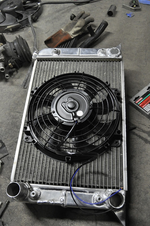
    Got a couple new goodies in the mail today. First up was an order from Summit Racing. Gotta love being in Ohio, one day shipping for the price of ground. This order included the radiator fan so I can get the radiator mounted and ensure I have enough clearance between it and the front of the engine.


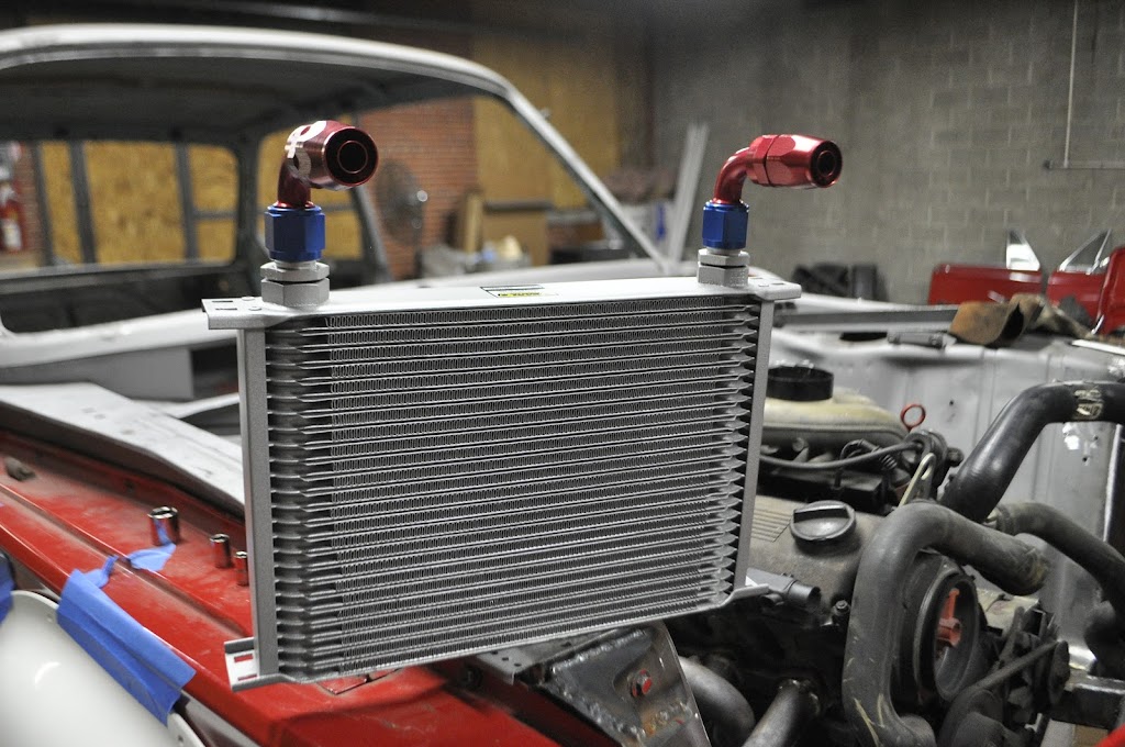
    I also got my Earls Performance Oil Cooler. This will let me ditch the stock E30 cooler, which doesn't really work very well to begin with. It will also let me relocate the assembly up higher, away from rocks and other road debris. The cooler is 13"w x 7.75"h x 2"t, which give almost double the effective surface area as the stock cooler.


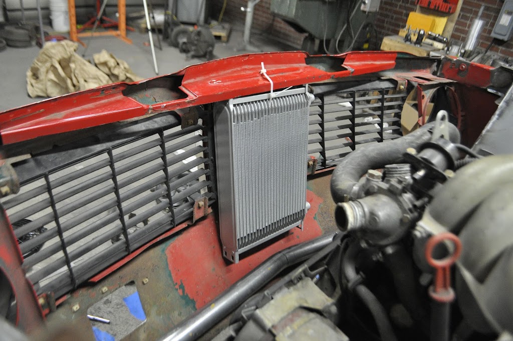
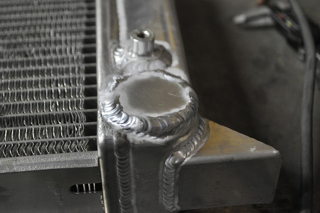
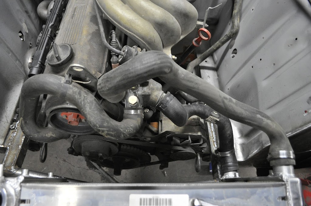
    Here you can see the radiator, fan and cooler in place. The cooler fits in the nose panel directly behind the kidney grills, then the radiator sits on the bottom cross member angled forward slightly. The fan has a minimum 3/4" clearance between it and the engine all the way around.


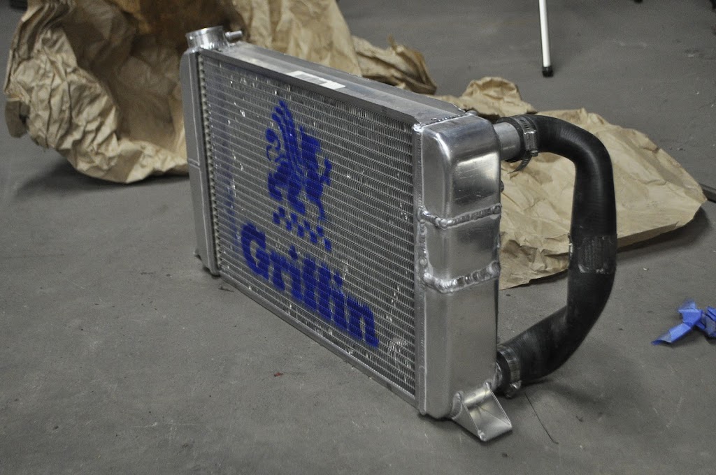
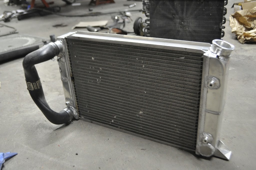
    Here's the business end of the coolers. In retrospect I kinda wish I'd gone with the black one, but I'm sure it will look fine once everything else is in there. On another note, I wonder if anybody has ever left the diving board mounting holes and just used that to run charge piping to a huge front mount intercooler... I suppose that would kinda kill the 'sleeper' theme though.


    And here's the position the Oil Cooler without the radiator in place. While the zip tie is a very high tech solution, I will be fabbing up some tabs off of the inner tubing structure for it to mount to.


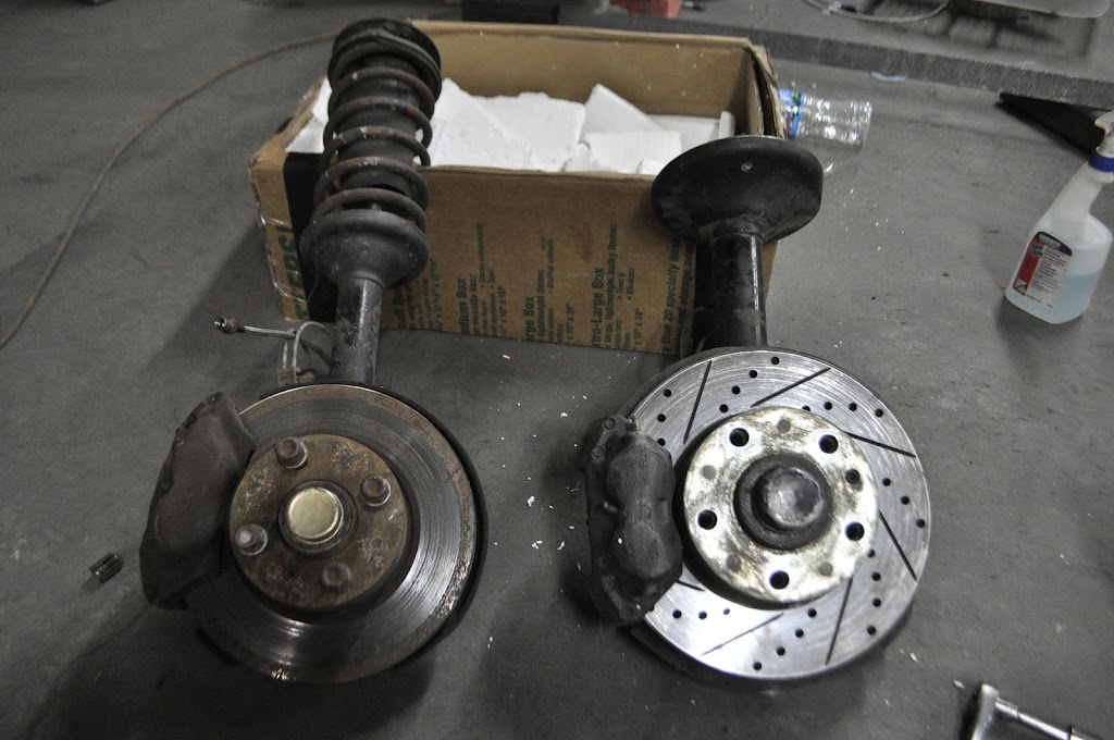
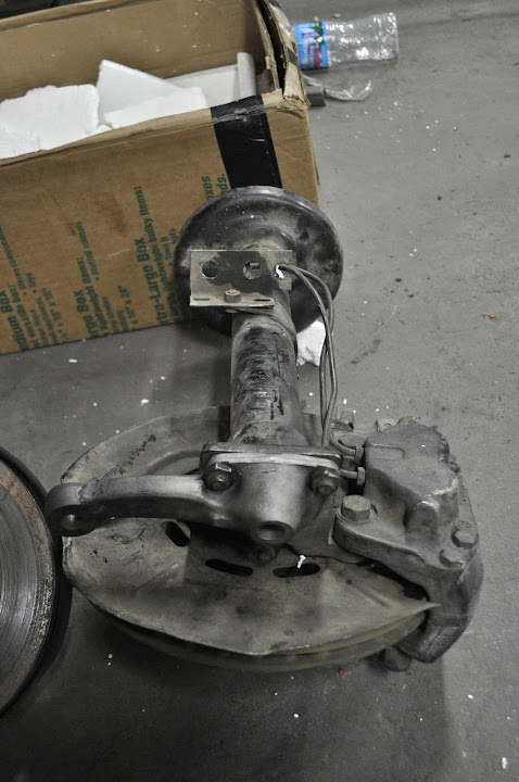
    The next set of parts that came in were my E12 front strut assemblies. Now why on earth would I want those some people may be asking. The 'short' answer is as follows:

    1) Big Brakes on the cheap - even larger than the 'volvo' bbk (280mm vs. 272mm) and 100% OEM BMW
    2) Larger Strut Tube - The strut tube I.D. is larger than that of the '02, which means you have MANY more choices for strut inserts, including the Koni Adjustable Race pieces (hint hint). And the O.D. is still small enough that the GC Coilover Kit for an '02 will still work with them.
    3) Tii Bearings for non-Tii Prices - The E12 shares the same larger bearings as the much sought after Tii spindles, only they don't cost and arm and a leg to buy. I was able to find the entire strut assemblies (including brakes and hubs) for under $200. To get even close to the same outfit with Tii bits would normally run upwards of $600.
    4) 5 x 120 Bolt Pattern - Now this may seem very unnecessary to some, and to each his own. Personally, the switch from 4 to 5 lug is worth it for the options in wheels alone (as you'll see next week). There are many old classic 5x120 wheels in 15" and 16" from the big coupes and sedans that sell for a fraction of what the 4 lug version do. It also opens up a lot of newer modern BMW wheels (if your into that kind of thing). I will also say the decision was easier for me due to my E30 rear subframe, you can swap Z3 hubs and brakes back there and your done.


    Here you can see the regular '02 strut on the left with the 'volvo bbk' and the e12 strut on the right with it's standard size brakes (cross drilled/vented not std):


    Now when trying to fit the E12 struts to an '02 there are two places that they need to connect to the car, the upper strut bearing and the pitman arm/lower ball joint. Since I'm running coilovers the upper strut bearing will be simple enough, just a set of '02 camber plates. However the pitman arm is a bit more tricky, or so I thought. The pitman arms on 2002's mount with three bolts (M8) and are aligned by a groove that is machined into the center of the arm. A matching lip on the bottom of the strut housing keeps the pitman arm where it needs to be. The E12 uses the same system, however it's held in place with three M10 bolts. Luckily, the groove and lip on the E12 parts is the same width and depth as the ones on the 2002 parts, and on closer inspection the top two bolt holes line up perfectly between the two struts. The third mounting hole is actually a couple of mm further down on the E12 part, but a couple of minutes on the mill and I was able to drill out the M8 holes to fit M10 bolts, as well as space the third hole down to where it needed to be. This left me with an E12 strut assembly with the 2002 pitman arm, ready to bolt onto any 2002 front subframe!


    The pitman arm in the above picture is one of the shortened arms I have for the e21 steering rack swap. Which brings up another benefit of the E12 setup. On the 2002, the brake caliper hangs off the back of the strut, while on the E12 it hangs off the front. When shortening the pitman arms for use on the 2002 strut, the tie rod end mounting point was moved very close to the brake caliper body. You can see in the above pic how the pitman arm and caliper are on opposite sides of the E12 strut housing. While the location on the '02 strut isn't a harmful issue, it is much nicer to have more room to get to the tie rod ends and brake calipers for maintenance.


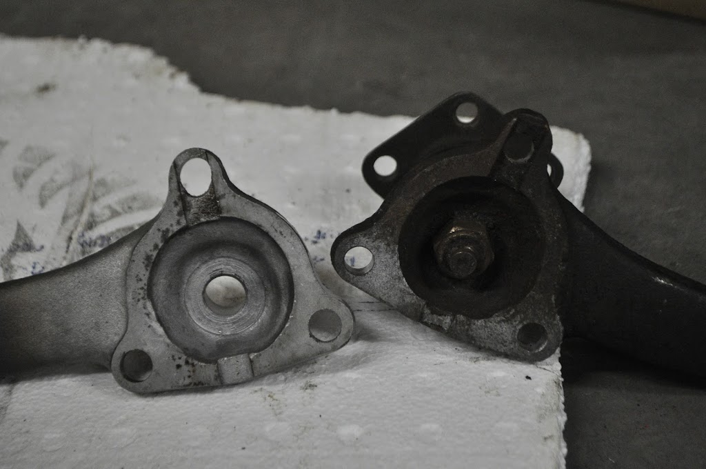
    Here you can see the modified pitman arm on the left and a stock arm on the right. As you can see there is still plenty of material around the edges of the arm considering the types of loading it will see.


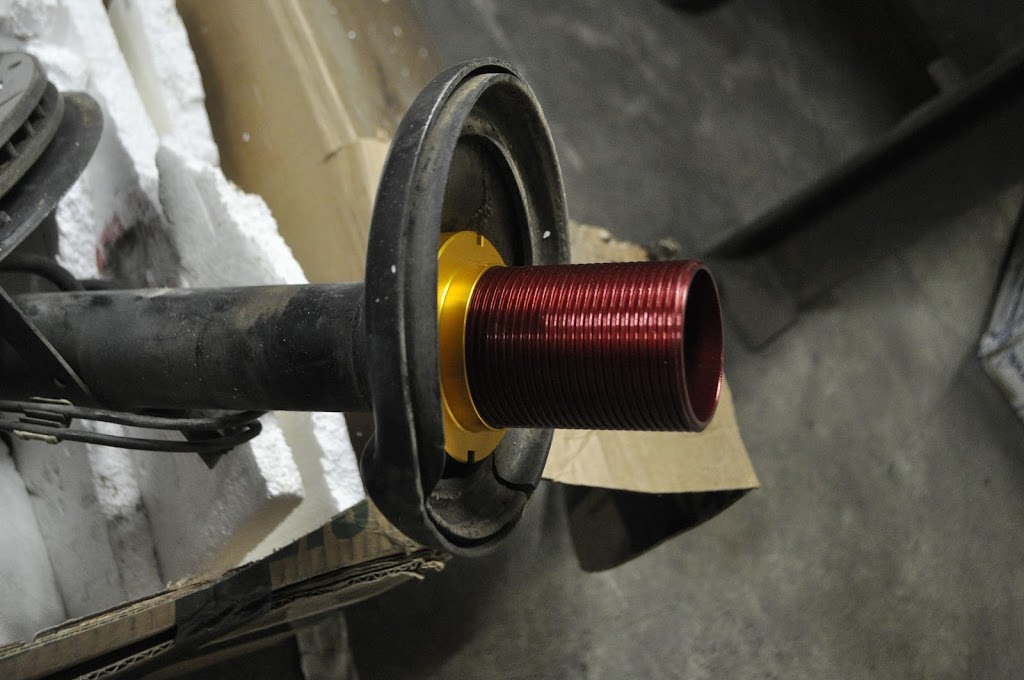
    Here are my GC coilover sleeves slid over top of the E12 tube (yea I still have to cut off the stock spring perch). A nice thing to note is that the sleeves actually fit perfectly around the E12 spindle tubes with very little slop (maybe 0.03"). The '02 spindle tubes are much skinnier, and so they would require a spacer to be very secure on the tube.


    I will also be making/buying a bump steer spacer for between the strut housing and the pitman arm. This will help to return the front suspension to the proper geometry on a lowered car.


    :hi:

    Leave a comment:


  • everlast
    replied
    Looks like you got that welding aluminum thing worked out.. Pretty awesome work on that rad.

    Leave a comment:


  • tinkwithanr
    replied
    Finished modifying the radiator tonight.


    Cut out a plug and welded up the old outlet port:


    Then I cut a new hole on the opposite side and welded the new outlet in place:


    The last thing to do was to make the internal baffle to make the coolant flow through the plates instead of just down to the outlet. so I cut out a section so I could access the middle of the driver side tank:


    Then I made a cardboard template for what I wanted the baffle to look like:


    Template turned into aluminum baffle:


    Baffle welded in place:


    With the baffle welded in place I put the cutout section back in place and welded it as well:


    Here's is a pic of it while I was doing the leak test. Luckily for me all my welds held! No leaks. Now that I know my welds functional I just have to work on making them look pretty lol.


    And here you can see how the modifications simplified the routing of my coolant hoses. I wish I could do something to move the water pump -> thermostat hose, I may try to fab up a hardline of some kind, but I'm not going to worry about that for now. Also, ignore the wonky bends in the coolant hoses in the pic, I just used some I had laying around. I'm going to try and find some more universal silicone ones that match the needed paths better.


    Thanks for looking!

    Leave a comment:


  • tinkwithanr
    replied
    Thanks! Glad you enjoyed reading through it.

    Leave a comment:


  • Denny
    replied
    I love reading restoration projects and read some good ones that inspired me on my own E30... but this right here is pretty damn impressive..!! Amazing job!

    Leave a comment:


  • tinkwithanr
    replied
    Sooo nobody (on any of the forums) was able to guess what this guy was for:


    I suppose it was a fairly hard thing to guess lol. Not many BMW's are running 6 LSX coils.


    I decided to use these over the normal BMW Coil-on-plug for two main reasons. First, the m20 doesn't have a very elegant way to mount a COP setup. It has been done, but since the spark plugs are on the side of the head it normally looks a bit hacked together. Second, since I'm using MS3X for my engine management, the LSX coils can be wired directly into the ecu. The BMW coils need a separate circuit to drive it, so simpler ended up being better.

    Here you can see how I angled them on the mounting board. This will let the plug wires be run nicely along the firewall over to the engine.


    Also, this was my first real part from aluminum the included welding. Overall the welds are getting better, but I have a long way to go. I put to much heat into it in a few places, but I'll blame at least some of that to trying to weld 1/8" sheet to 1/2" tabs.


    And here is where I will be mounting it in the engine bay. I'm hoping to be able to use the stock plug wire holder (slightly modified) or make a new one that mimics it's function. That will keep the wires from draping across the valve cover or falling down onto the headers.


    I swear those headers look better everytime I look at them...


    Next up on the list was to tear into a perfectly good radiator. I bought it back before I figured out how I wanted to run my coolant hoses. Now that I've figured that out, of course the outlet for the radiator is on the wrong side. In order to fix this, I cut off the outlet from the passenger side.


    Next I'll make a plug for where the outlet used to be. I also had to reduce the diameter of the outlet from 1.75" to 1.5". To do this I just cut out a section and welded it back together. Here you can see that the inlet and outlet are the same size, like on a normal M20.


    And here you can see how it will be once I weld the outlet in it's new location. The last modification I will have to make is a small block off plate that goes in the middle of the driver's side. This will direct the coolant from the inlet -> across the top half of the radiator -> down the passenger side reservoir -> back across the lower half of the radiator -> out the outlet. I didn't feel like going through the heat transfer equations to see exactly how this would effect the cooling, but considering Griffin Radiators also offers the exact same setup I'm making now (if only I would have bought that to start with) I'm sure it will work just fine.

    Leave a comment:


  • tinkwithanr
    replied
    Originally posted by deutschman View Post
    That makes compleat sens. I hope I'm not being annoying by bouncing ideas around. Hopefuly having some alternative thought is helpful in some way.

    Not at all! Hopefully I didn't come off as annoyed in any of my previous replies. I know there's a bunch of stuff I haven't thought or or seen, and the last thing I wanna do is shut myself off from it. I hope everyone feels free to comment on anything you see in here. Even if it's something I already know (which isn't that much!) having it documented in here means that someone else can learn from it as well.

    Leave a comment:


  • deutschman
    replied
    That makes compleat sens. I hope I'm not being annoying by bouncing ideas around. Hopefuly having some alternative thought is helpful in some way.

    Leave a comment:


  • kronus
    replied
    Ah, there we go.

    Leave a comment:


  • KillaCam
    replied
    damn!! those headers are super dope nasty!

    this thread is inspiring!

    Leave a comment:


  • tinkwithanr
    replied
    I should be in the bay area in the next few months. It really depends on how my jobs hunt goes, it's hard to justify moving without having a paying job waiting for me.


    It's not really easy to see in any of the pictures I've posted, but the front clip actually has a lip that extends beyond the mounting edge on each side. So when fitting it up the nose clip can actually rest on the lip and it holds it in place pretty well without any bolts in place. From there it's pretty easy to line it up one side at a time.

    Leave a comment:


  • kronus
    replied
    Thanks for the info on the bead roller! I'll look at picking one up, there's some sheet metal work we need to do.

    For the panel and bolt shearing issues, that's going to be annoying to mount if you have to hold it up exactly to fit the bolt holes. Maybe some guide pins would simplify the process and take some shear off the bolts.

    When are you heading to the bay? I want to see this beast in person!

    Leave a comment:


  • tinkwithanr
    replied
    I looked at a couple of different options for how to hold to front end on. I'm pretty sure those quick connectors you linked to are meant more for lightweight fiberglass or carbon fiber body panels. The nose panel, while heavily gutted, is still pretty heavy. I would be concerned with them being able to hold the weight, especially considering the mounting surfaces are vertical putting the load directly onto the bolts in shear.

    Also, I'm not planning to take the front end off every other day like most race teams might want to. Because of the way the front end goes together you have to remove the fenders before you can take off the front clip (it has to do with how the front edge of the fender wraps around the corners of the front clip), plus I'll have to take a couple of screws out of the turbo body kit. All that taken into consideration I figured the best way to hold it on would be the same way the fenders are held on. I'm not to worried about them wearing out because I'm going to use the stock 'clip nut' like the fenders do as well, I just haven't installed them yet. If one wears out I can just order some new ones and pop them in place.

    Oh, and pm send your way.

    Leave a comment:


  • deutschman
    replied
    Nice job on the front end. It seams like you would want to go with something like these quick release fasteners for the front end.
    Hoerr Racing Products serves the motorsports industry by providing parts & accessories including lubricants, brake systems, shocks & springs, driver & crew to customers worldwide.

    Your not worried about the OE stile screws getting warn out and loose on the front end? Seams like they would be annoying to take in and out as well.

    Leave a comment:


  • tinkwithanr
    replied
    Originally posted by 325Drew View Post
    awesome just plain awesome!!!!:D
    Originally posted by CubbyChowder View Post
    awesome progress! I love this build
    Originally posted by obes View Post
    keep it up! look forward to seeing this monster
    Originally posted by silence View Post
    looking good!
    Originally posted by CorvallisBMW View Post
    I love this project! Fantastic fab work
    Originally posted by downforce22 View Post
    Even better with RD headers!! This guy never stops delivering!

    Thanks guys. So nobody has any guesses on my aluminum part?;)

    Leave a comment:

Working...
X