1986 325iX 3.1L Stroker + Turbo

Collapse
X
 
  • Time
  • Show
Clear All
new posts

  • downforce22
    replied
    Originally posted by tschultz
    Take off the ignition coil plug wire so the engine can't start. Then crank maybe 5 times. Then let it idle and make sure you don't have leaks etc

    Oil cooler I believe has a built in thermostat, so it shouldn't open until the temperature goes above the set cracking temperature.
    Thanks I'll try that.

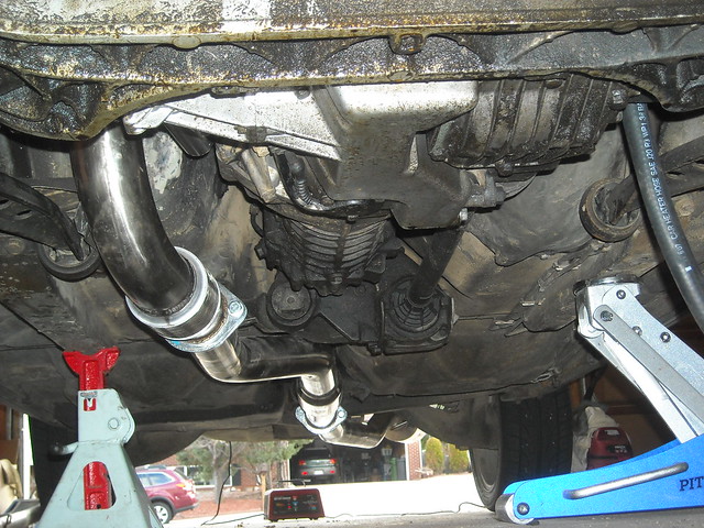
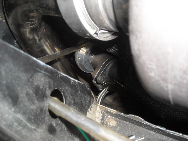
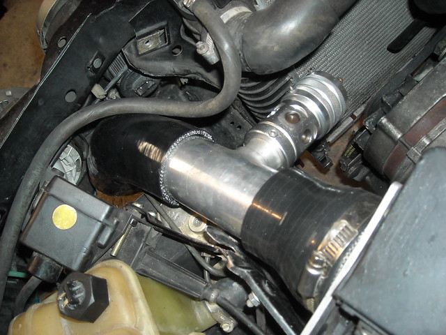
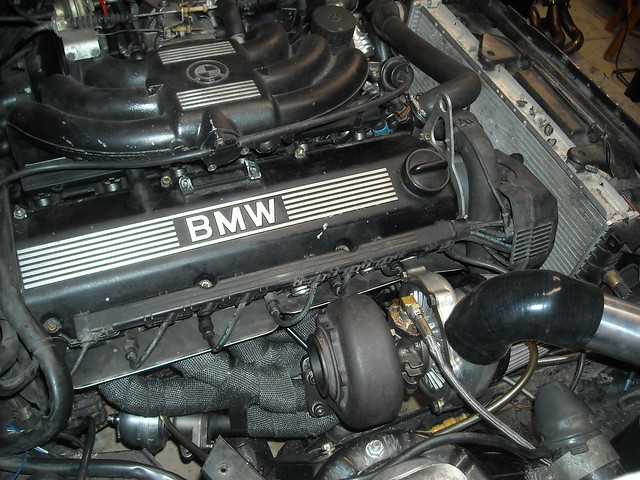
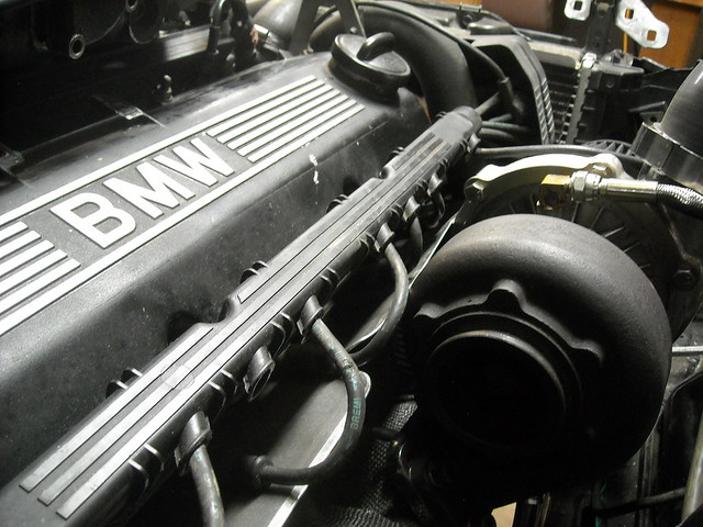
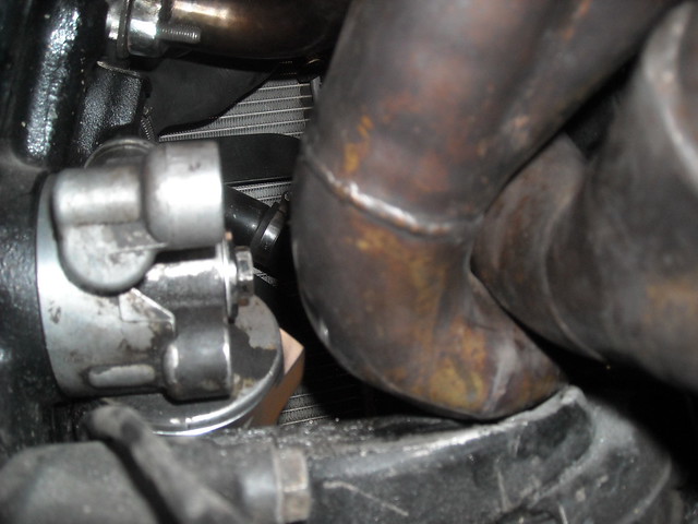
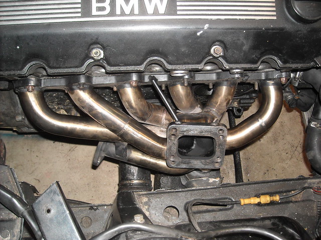
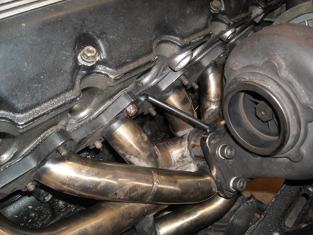
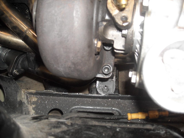
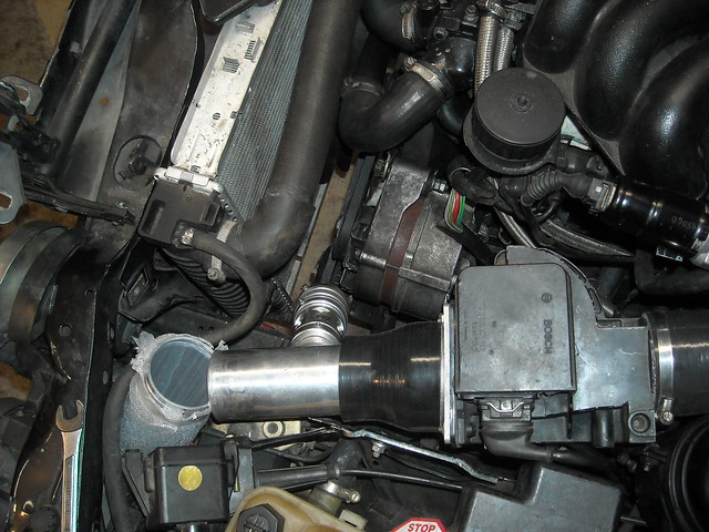
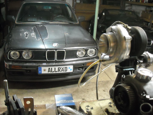
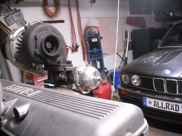
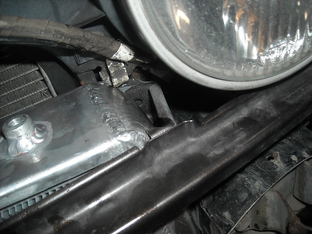
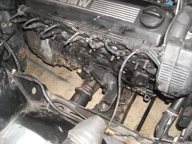
    The car is very close to starting, but the 2.5" V Band clamp that I got does not quite tighten the turbo to the exhaust. I'm going to get another and see if that will tighten it together, otherwise I'm not sure what I'll do. Its like one side of the clamp doesn't quite clamp the v band lip as tight as the other side.

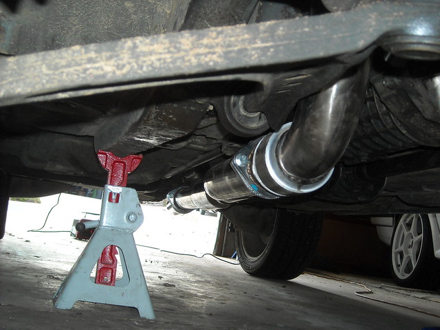
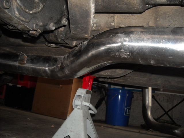
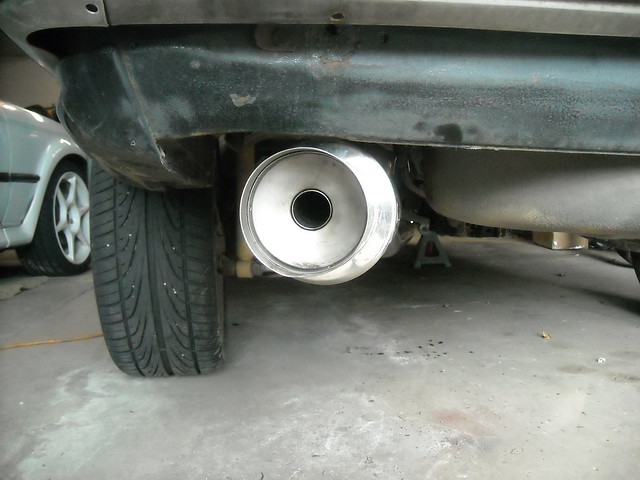
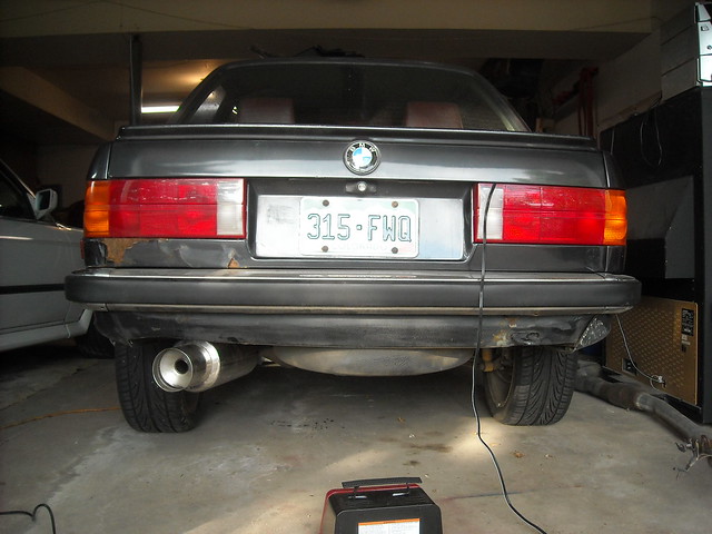
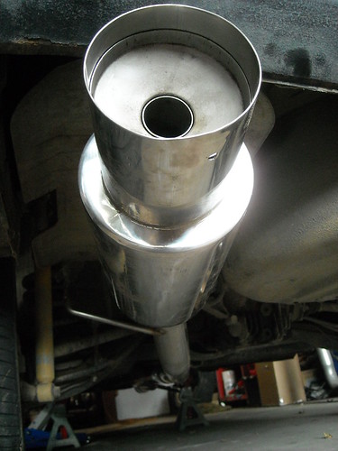
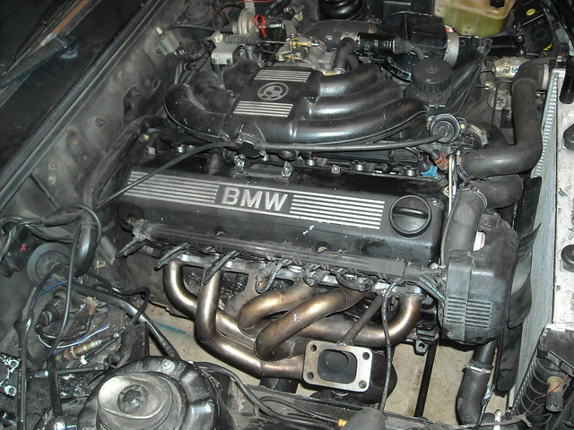
    On to the exhaust. The fart cannon is mounted!


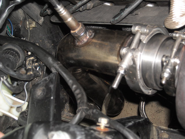
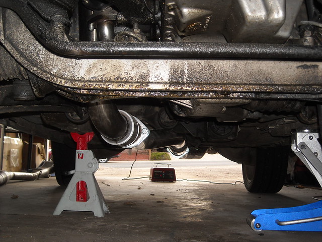
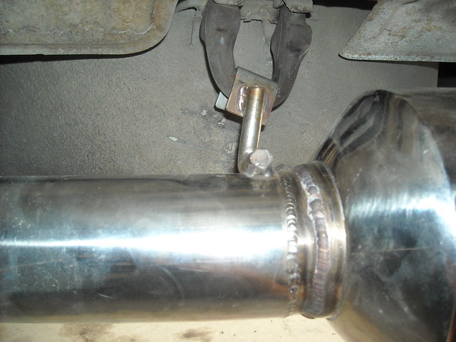
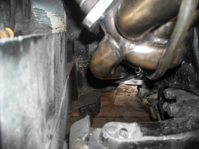
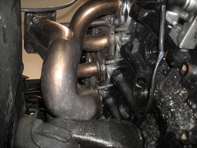
    The spacer to go from 2.5 to 3 inch put the downpipe in a perfect location for this exhaust.


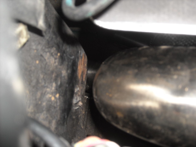
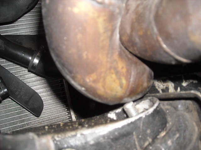
    It comes near the LCAB but there is a shield here.


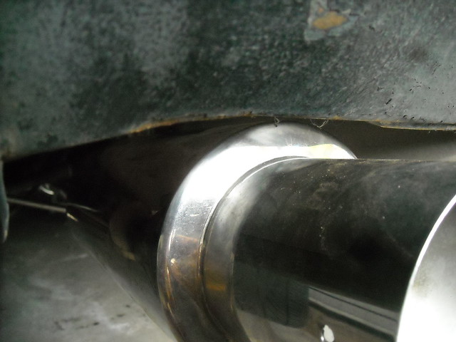
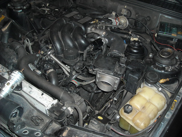
    It is about as tight to the body as possible for an exhaust designed for a rwd e30. This is the cx racing 3" turbo back stainless steel system. It was purchased by the previous owner so I decided to give it a shot.


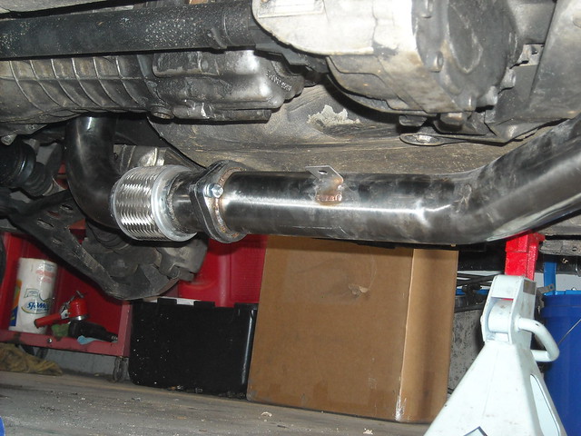
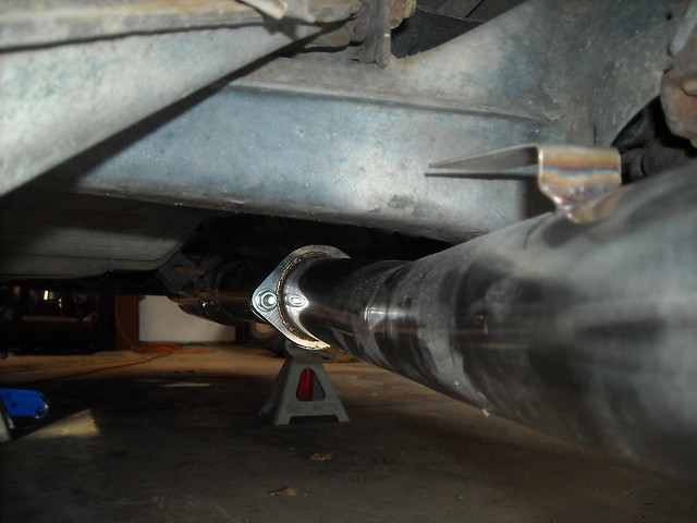
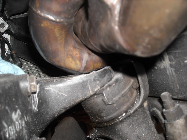
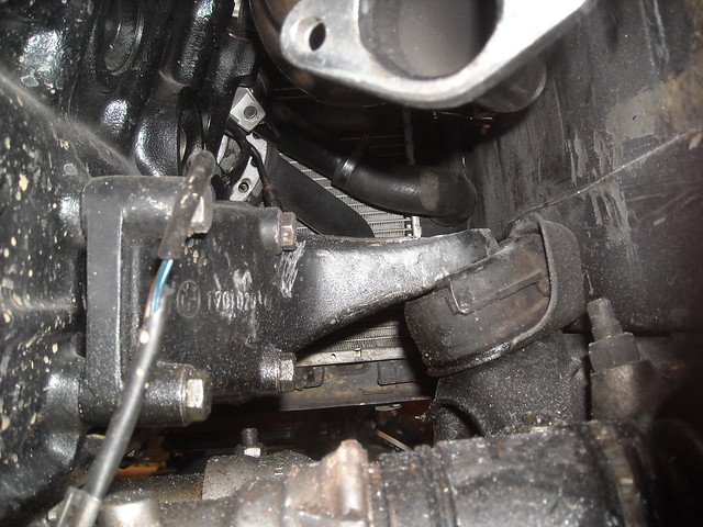
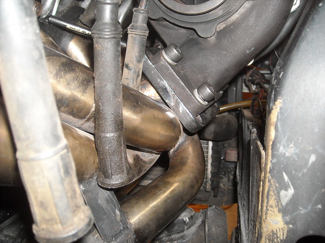
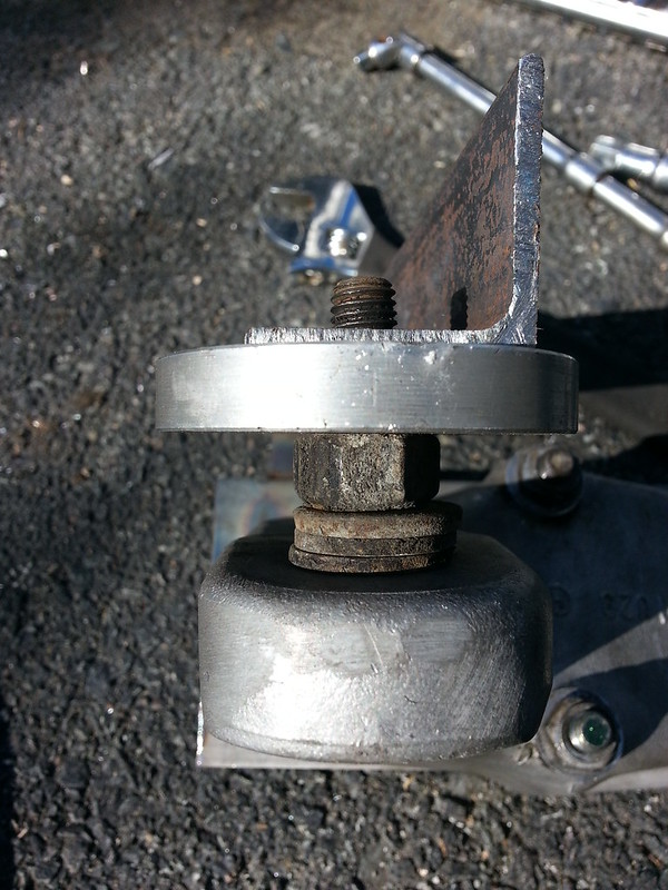
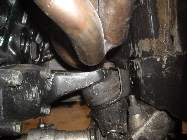
    Comes very close to the mount here but it fits.


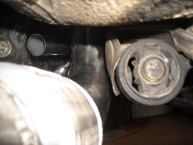
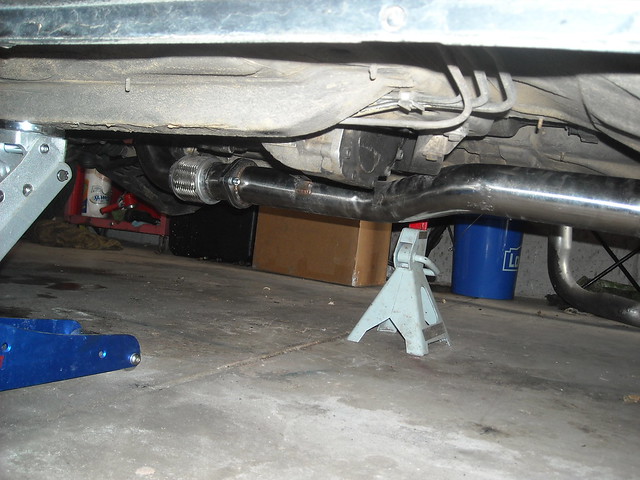
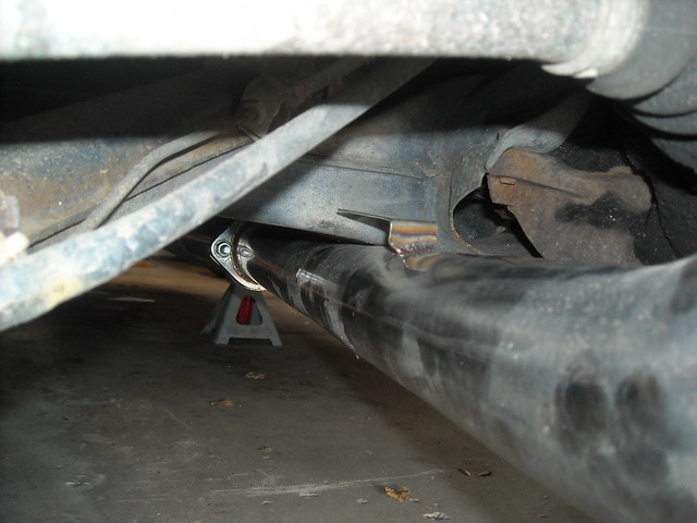
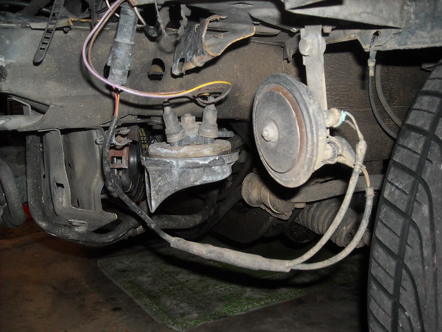
    Here it barely fits under the rear subframe.


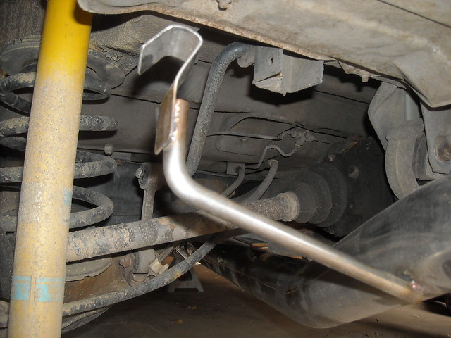
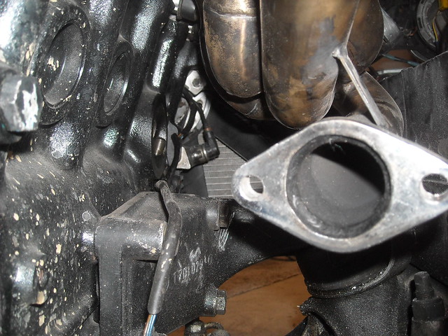
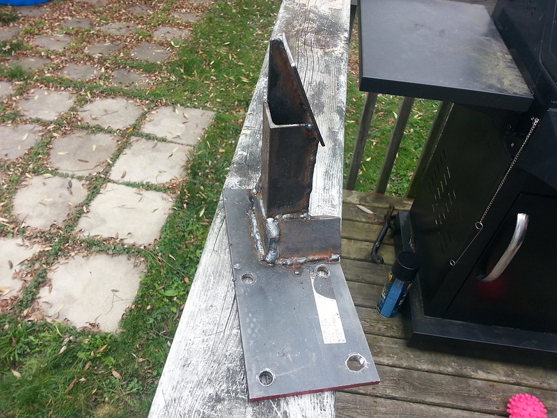
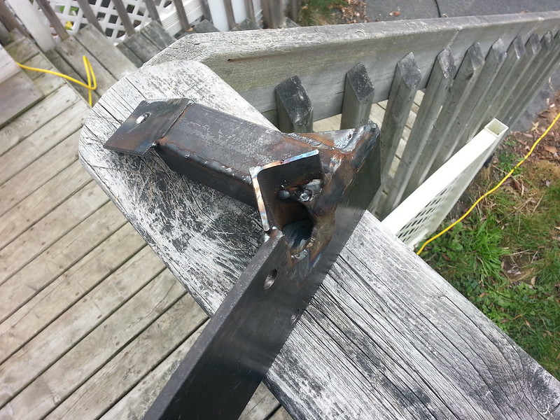
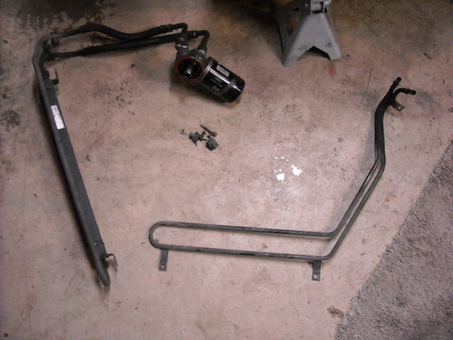
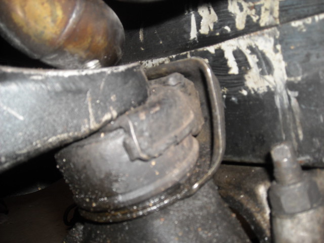
    Not sure what this mount is for?


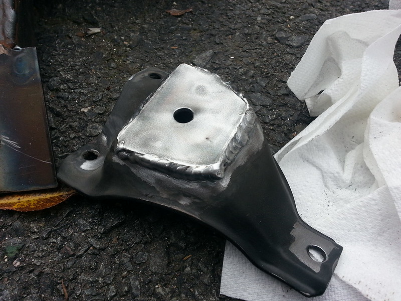
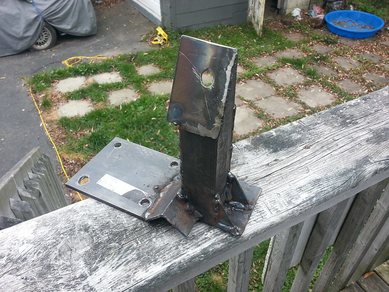
    The factory e30 mount fit just right to the mounting position on the exhaust/ fart cannon.


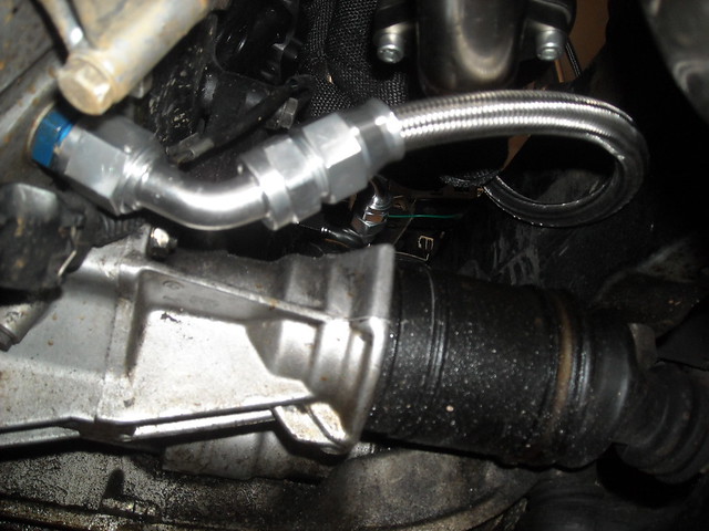
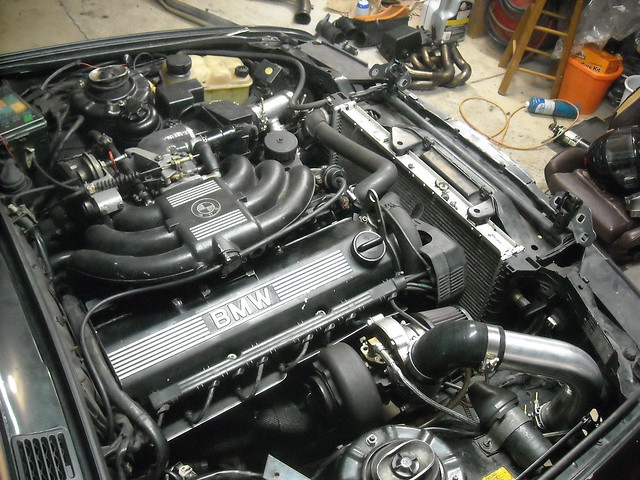
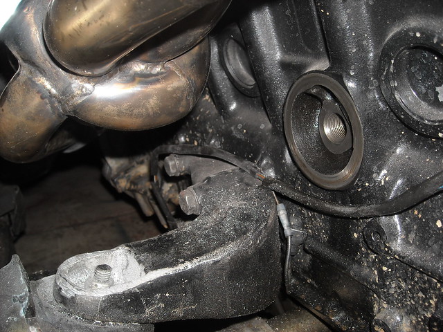
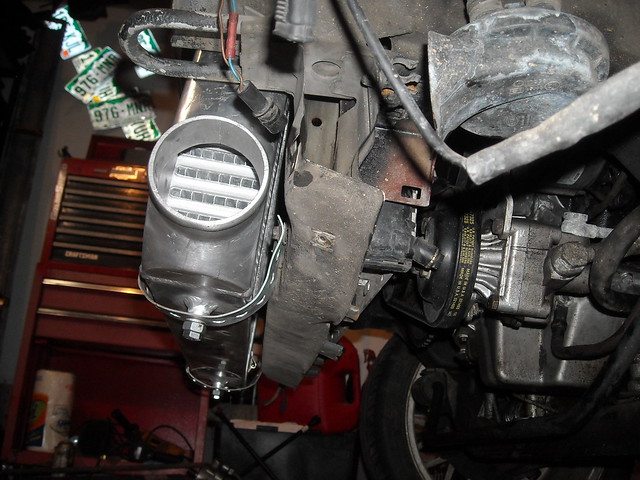
    The screamer pipe is mounted and fits well.


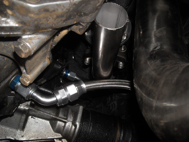
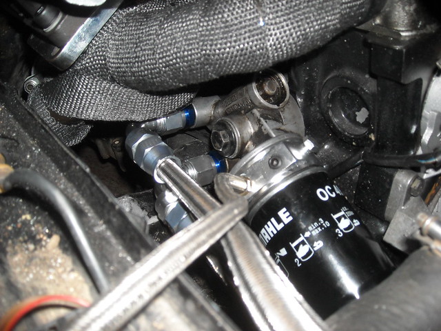
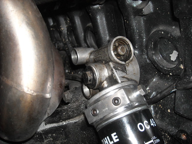
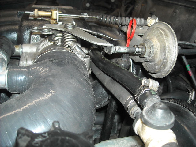
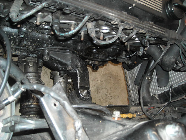
    And the oil drain is connected.


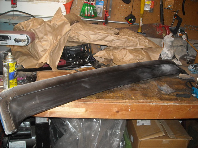
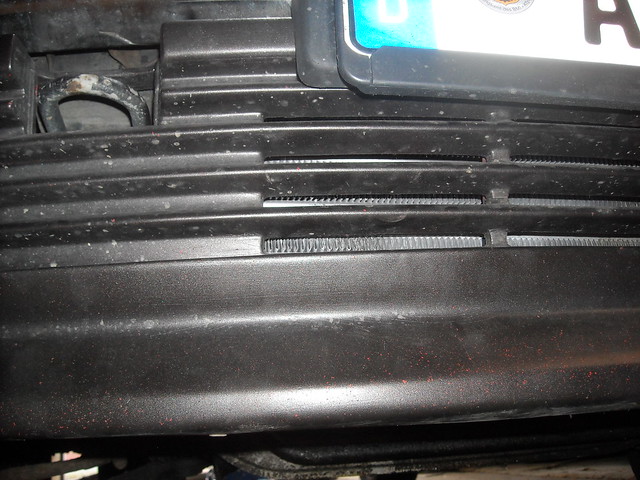
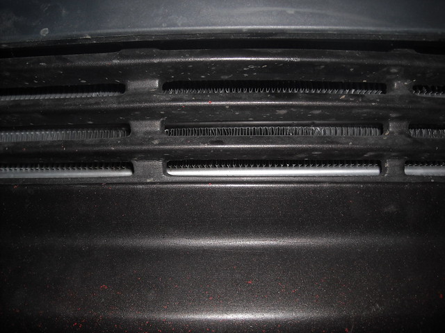
    I also started on the e28 spoiler to get it painted and cleaned up


    I may order another 2.5" V band clamp and then a change to my tune is all I need before startup!!

    Leave a comment:


  • tschultz
    replied
    Take off the ignition coil plug wire so the engine can't start. Then crank maybe 5 times. Then let it idle and make sure you don't have leaks etc

    Oil cooler I believe has a built in thermostat, so it shouldn't open until the temperature goes above the set cracking temperature.

    Leave a comment:


  • 2002jm
    replied
    ix:)

    I think I want an ix again!:). Had 3 maybe the forth would be a keeper:)
    This is a very nice project,
    jm

    Leave a comment:


  • downforce22
    replied
    Thanks for that, I did test it and it is a horn like you said. I don't plan to use the code feature anyway so I pulled it off. If I decide I want it back I have a spare horn.

    I test fit my cx racing turbo back 3" exhaust and it should fit. It may not hug the body as much as I would like due to the awd components but I will fit it up and see where it ends up.

    I am waiting on the 2.5" Vband clamp to connect up the downpipe. I drained the oil, hooked up the oil drain line, bolted up the screamer pipe, hooked up the oil cooler, and refilled with new oil. With the screamer pipe and oil drain in place I could test the fitment of the downpipe. It turns out it will fit perfect and clear everything due to the 2.5 to 3 inch adapter, it spaces the exhaust back 2 inches. This seems like the only thing that has worked well so far haha.

    I will get some photos either this weekend or early next week and some time to start her up.

    I am thinking it would make sense to ensure the oil system is working right and prime the system. Is there a way I can get the oil circulating through the filter, turbo, and oil cooler before starting the car? Is this even worth worrying about?
    Last edited by downforce22; 05-07-2015, 08:02 PM.

    Leave a comment:


  • hendrixvodu
    replied
    The extra horn is the obc alarm horn. If you set your code and try to start the car 3 times it should set off that horn

    Last edited by hendrixvodu; 05-06-2015, 05:50 PM.

    Leave a comment:


  • Nisse Järnet
    replied
    Yeah it looks good! I have the same switches haha :)

    Leave a comment:


  • nomansland92
    replied
    looks great!!!! I can't wait to see how this thing runs

    Leave a comment:


  • downforce22
    replied
    I test fitted all of the piping and then decided to clamp it down.


    Turbo XS Type H BOV


    I also got my oil system set up. The sandwich plate should work great. I am running 10-AN lines to the oil cooler and had to snag a couple of fittings to make it work. Oil cooler above the intercooler behind the kidneys. This also moves my filter to a move accessible location without the ac bracket in the way. Oil Pressure sender and oil feed line come off the sandwich plate.


    Couplers hooked up using T bolt clamps.


    I had to trim the bbs valence a little but didn't want to cut through it so I could maintain that stealth look. ;D The bbs valence has some holes that areperfect to get airfow to the intercooler. I am considering adding more holes in the bbs valence (under the bumper) to get more airflow to the turbo.The bottom is flared out a bit as the spoiler is squeezed against the 90 degree reducers on the ends of the intercooler.


    It looks like with minor trimming the passenger fog will fit. I am not sure if the driver side fog will fit though.


    I also took a couple shots of the interior. It still needs work but has turned out well. You can see my switch above the radio. It dawned on me I could have used a spare window kill switch for these lights but this switch seems easier to operate than those stupid window kill switches.


    Things to do:

    - Mount oil cooler and connect to oil lines
    - Change oil and connect oil drain to oil pan
    - Connect downpipe and oxygen sensor and rest of the exhaust. Waiting on 3"-2.5" V band adapter
    - Mount screamer pipe
    - Figure out oil catch can solution
    - Plug elbow on the throttle body from the crank case breather hose
    - Plumb the vacuum line from the blowoff valve to the fpr
    - Tune the car

    I think we are very close!
    Last edited by downforce22; 05-01-2015, 06:46 PM.

    Leave a comment:


  • downforce22
    replied
    I decided to try to modify the manifold and the motor mount to get the manifold to fit. It turns out even after my modifications it is too close for comfort. Here is a picture after modification. The manifold is on the exhaust studs in this picture but it is still touching the mount and would heat that up in a hurry.


    I noticed another issue with this manifold that had to do with the oil feed and return lines for the oil cooler. With the -10 an lines, there is not much room for a 90 degree fitting wihtout hitting the manifold.


    So i resorted to trying the other manifold. Kameron aka KAMotors had this manifold on his car for a while so I think it will be ok. Check out the video of his car on the Tuned episode with Matt Farrah.


    Clearance is much better for the motor mount and oil lines as you can see below.


    Then I tried to fit the turbo and it was interfering with the strut tower so I rotated the compressor housing. While I had it apart, I decided to take a look at the compressor. It looks pretty good and spins freely. I did not see any sign of interference with the housing and the compressor blade. Notice the -10an fitting and cylinder head in the picture for size reference.


    Clearance is much better with this manifold overall. Lots of room around everything.


    Then I decided to work on the intake piping. I still need a few parts but this helped me determine what components may or may not work. I noticed many people use elbow couplers to make bends instead of the cutting the aluminum piping to the exact required length for bends. It just so happened the previous owner had cut a few holes in the underbody close enough to the right spot that they could be still be used.


    I will use a 90 degree coupler and another 90 degree aluminum bend to connect to the compressor.

    And on the other side I still need a 45 degree reducing bend to connect it all up. A bit of trimming it necessary but it should work.


    Since I don't have the necessary intake couplers or the components for the oil system I decided to wire up the gauges. Shout out to euwerks for the free gauge pod housing! The style and texture is top notch. I just need to figure out how best to mount it.


    I also didn't like how dark the interior of the car is with the tint, red seats and black carpet/ door panels at night so I picked up some orange leds from ebay (china). I wired them up in series but the leds didn't have enough current so I had to rewire in parallel. I also decided these would be neat on a switch so they could be turned on and off at will. I bought a simple/ correct looking switch from the auto parts store and used a spare filler blank to mount the switch in my last empty slot above the radio.


    The passenger side looks great under the glove box, but I had to be creative on the driver side since my kick panel doesn't stay in very well. I wanted it to be decently bright if the kick panel was in without mounting it directly on the kick panel itself. I decided on mounting it to the speaker panel for now. And my switch works great hooked up to a hot 12v ignition wire.


    I decided I don't want to use the cx racing manifold long term and got in on the good n tight m20 turbo manifold group buy. It should work fine on the iX and looks like great quality. Here are a couple teasers. Unfortunately it won't be here for a couple months...


    I'll be picking up a bunch of parts this week for the oil system so stay tuned
    Last edited by downforce22; 04-26-2015, 08:09 PM.

    Leave a comment:


  • Nisse Järnet
    replied
    Originally posted by downforce22

    Also, what is this next to the horn on the drivers side?


    Either way, some progress finally!!
    Its another horn :)

    Leave a comment:


  • Northern
    replied
    Took me a bit, but I found some pics of what I mean. The welds are awful, and the general design is ugly as hell, but I didn't have the experience or tooling then that I have now lol. Hopefully it gives you an idea of how to do it better:

    Building the jig to mount lower:


    Mount "tower" reinforcement:


    Mount arm:


    Very ugly pressure sender notch.

    Leave a comment:


  • Northern
    replied
    I've mentioned it a few times, but that manifold does interfere heavily with the stock mount arms, like 1" plus. I filed the top of the mount arm down a lot, but I quickly realized it wasn't going to fit.

    My solution was to make a jig from the original mount arm, then make a new arm that mounts much lower and uses a much thinner bushing.

    Leave a comment:


  • downforce22
    replied
    I was chasing down an overheating issue that didn't seem to make any sense. I believe I got some air in the system causing the overheating. Nonetheless, after bleeding the system, changing the t-stat, and flushing the coolant it sits right around 190 F during normal operation.


    So I began tearing into old smokey to get this party started. :devil: Here are a few before photos.


    To fit the intercooler, the power steering cooler and oil cooler was in the way. I removed both as I also need to figure out how to fit the oil cooler lines with the exhaust manifold I was planning to run.


    To keep the power steering system, I removed the lower loop from the power steering return and connected the inlet to the cooler directly to the rack and removed the cooling loop.


    The intercooler is a tight fit behind the valence. I found there are 2 types of mounting brackets that bolt to the radiator support. Either could be used, but one type would need to be removed and reattached 180 degrees the other way. I really did not want to have to cut the valence much and I was lucky enough to have brackets facing the right way. This is the bracket I am taking about and how it fits with the intercooler fitted. The intercooler core is 24"x12"x3" with 3" end connections. It is obviously wider end to end due to the flanges on each side. I reinstalled with the bolts in place and they limit the upward location of the intercooler. That and the center valence piece holds the intercooler tight.


    Here are my temporary mounts bolted into the oil cooler mounts.


    Next up was the intake line from the throttle body to the intake boot. It had to be removed. Luckily the hose I removed from the power steering cooler was long enough. I removed the old line and replaced it with the trimmed hose and it fits great. Seen here is the German Engineering intake boot installed also.


    I am keeping the AFM for now. Trying to figure out how to route the intercooler hoses and fit the blow off valve.


    I had made a custom bracket to move the ABS thing in black and put the coolant reservoir on the drivers side. I bent my custom bracket and i have a straight shot toward my intercooler access hole.


    I decided to pull out my fuel rail and replace the injectors. The stockers may be running out of steam at higher rpms anyway.


    From left to right, stock 14# injectors, 24# mustang blue top injectors, and 30# bosch injectors.


    The stock and 24# injectors have a similar nozzle configuration, but the 30# injectors have a quad-orifice design. I am assuming that is for better fuel atomization.


    I looked into the part number on these bad boys. They are Bosch 0-280-150-911. They are 30# at 2.7 bar, which equates to 33# at 3 bar and should support 300 horsepower.


    Installed. And now on to the exhaust. In the picture below you can see the gold cap I have on my oil drain next to the axle bracket bolted to the oil pan.


    Oil filter and lines removed for clearance testing.


    The exhaust manifold should fit, but right now it hits the motor mount. Take a look at all of the photos.


    In the second picture you can see how far the manifold studs are from fitting. It needs to come down and towards the rear of the car. So the motor mount and the bolt for the motor mount are preventing the manifold from fitting.

    Options:
    1. Grind manifold and motor mount down to try to clear
    2. Fabricate a different motor mount
    3. Modify the exhaust manifold
    4. Other???

    What do you guys think?


    Also, what is this next to the horn on the drivers side?


    Either way, some progress finally!!
    Last edited by downforce22; 04-13-2015, 05:59 AM.

    Leave a comment:


  • downforce22
    replied
    Originally posted by whodwho
    It will work wired that way but not as solid of a signal.
    The oil collection is common I drill a small hole in the lowest part of the cover for a drain when running the stock TPS.
    Did you re-jumper the ECU for the variable TPS?
    Changing the TPS shouldn't change the maps if you are running speed density
    I swapped the TPS wires and it works now. The ECU must have been jumpered for the vTPS because it would cut out like you described at ~70% throttle. My map is close but it still needs tweaks and I have not been into the 100% throttle part of the map.

    After I got her up and running she is starting to overheat so I ordered a low temp thermostat and am waiting on that to get her back on the road. I plan to start the turbo install this month.

    Leave a comment:


  • whodwho
    replied
    It will work wired that way but not as solid of a signal.
    The oil collection is common I drill a small hole in the lowest part of the cover for a drain when running the stock TPS.
    Did you re-jumper the ECU for the variable TPS?
    Changing the TPS shouldn't change the maps if you are running speed density

    Leave a comment:

Working...