
So. Many of you were following the FX-R projector retrofit that I started in late 2011. Yeah, 2011. My dawdling skills are second to none and since then I have blown the engine on my E30 (and got a new one built for it), got married and bought a house. Life tends to get in the way of car projects. Despite that, I am finally back on the wagon and have made big steps in this project.
Original thread:
As of now, I have one finished adapter plate (out of the two that I will need). The other one will get made over the next couple of weekends. Enough typing though, ain't nobody got time for that. Actually I do, so prepare to get your read on suckas.
I started out by getting my material blanks prepared with the necessary tooling holes. As my father has always said when it comes to cutting ANYTHING, "clamping is everything".
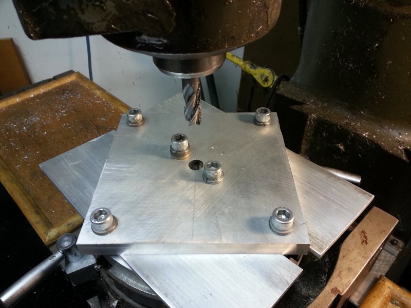
Many cuts later. The digital position readouts on the mill died a while back so this was all run manually the "old school" way...counting ticks/revolutions and doing cuts in only one direction per axis thanks to the ~50 mils of backlash in X & Y lol. I really need to go get some new readouts, manual mode sucks. I got MUCH better results on this one than my first one since I spent a lot more time thinking out the order of operations, and I made a drawing that called out my "tool paths" for each cut so I wasn't trying to subtract cutter diameters in my head while I did it. The first pass on everything left 35 mils of material, then I took off 25 mils and then the final pass was 10 mils on everything. Trying to hog it all out in a single pass is a recipe for crappy surface finish and lousy accuracy.
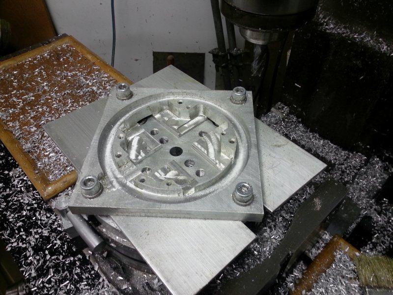
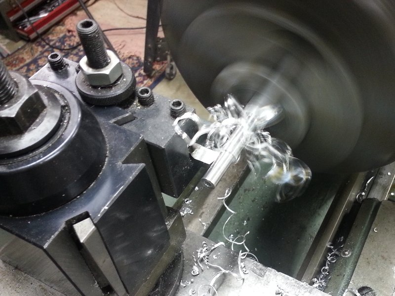
This was the final operation, and the one that I was most nervous about. Cutting the thing out of the original blank. Clamping was a little challenging just based on cutter clearances and the holes that I left available in the tooling plate (the threaded holes in the pic above). Anyway, it worked out just fine. I stepped through the Z/depth in 6 passes to avoid putting too much force on the clamps in the middle, and then made some light passes to get the diameter right.
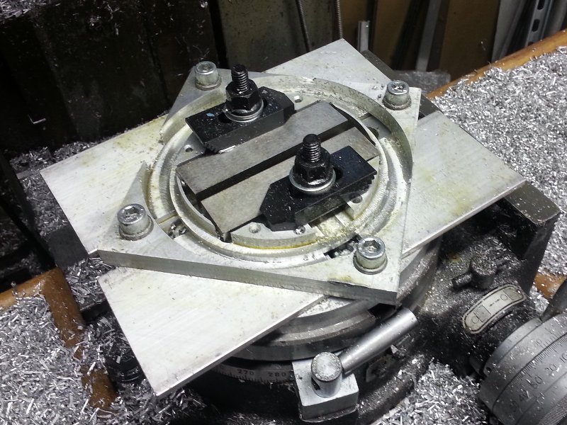
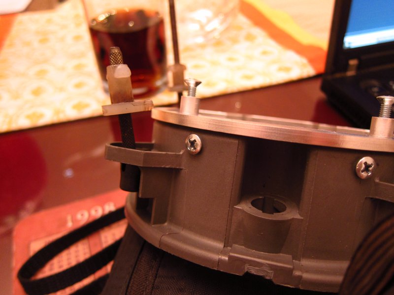
Originally, my plan was to make some little cleats that would be screwed to the plastic buckets and then the adapter would screw into those. Well, since I am using much thicker material than originally planned, it became an option to use radial screw connections between the adapter and housing. Much simpler! It will still get sealed with RTV, but I don't trust adhesives enough to just glue the plates on. Here you can see the setup for making the radial mount holes.
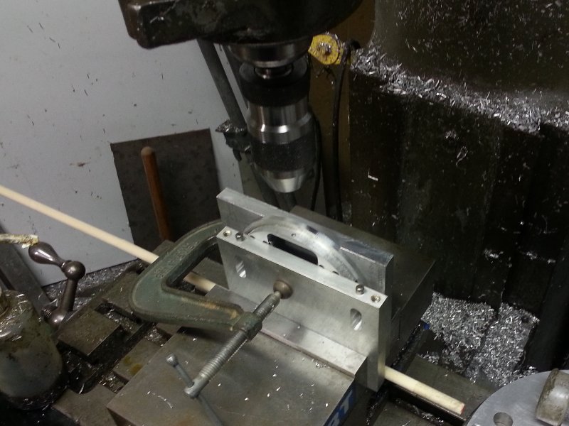
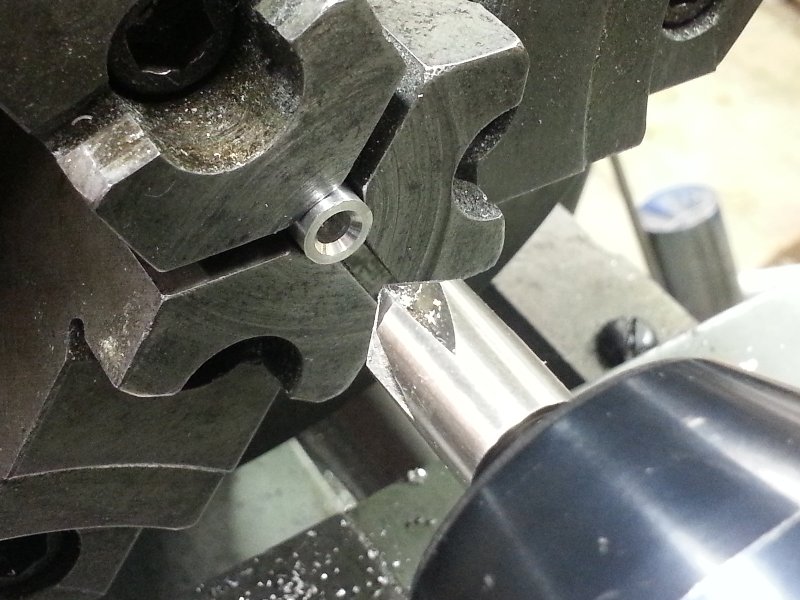
Next up were some little spacers. Because I simplified the adapter design to be made as a single-sided milling operation (the original plan involved flipping it over, re-indexing it and machining the second side), I needed some little precision spacers for the FX-R projector bodies.
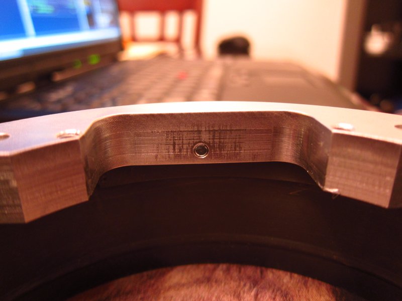
Finishing one up. I love macro shots lol.
Much to my relief, it fit FLAWLESSLY. No slop, no play, no grinding needed.
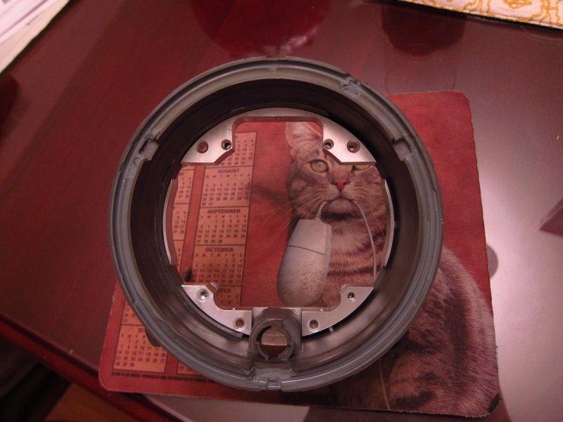
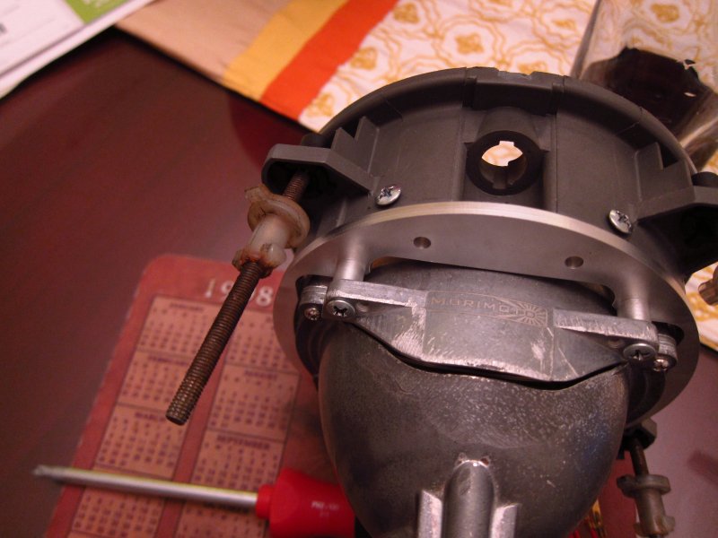
In case you were wondering about those radial holes, here's the deal. There are 3 of them (1 at the bottom, 2 about 30° off-center at the top). The screws were just to hold it together for the test-fit and I have some proper ones on order form McMaster.
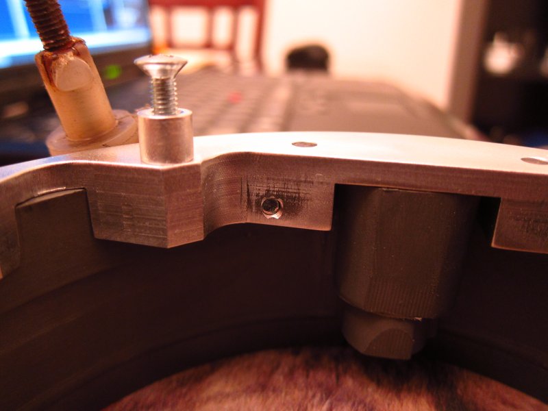
Those little spacers doing their job here. Note the two open holes in the adapter between the spacers. I'll mention those at the end.
Looking good! There is about ±0.5mm of play available in X & Y for fine-tuning the centering of the lens in the housing / "smiley" trim ring since I used M4 screws and the holes in the projector are 5mm. Mixing inches and millimeters in a design. Fun times. I wish I had metric lead-screws for the mill lol.
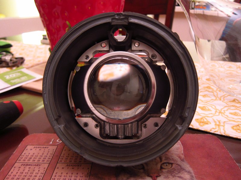
Using some countersunk screws to force the projector into alignment with the adapter, the fit is nearly perfect. I may want to nudge it about 10 mils to the left, but then again it doesn't really matter in any functional sense and nobody will ever see (you can't in this picture).
I double-checked the clearance between the lens and projector and there is (a safe) 2mm. There's about 0.5mm between the projector and "smiley" trim ring, so it's dead-on like I wanted.
I will be sealing up the gaps with some high temperature (-30°F to 325°F) weather-proof aluminum tape that I ordered on McMaster. The high-beam solenoid wires are getting run through some weatherproof silicone rubber grommets that will be mounted in the bottom of the plastic headlight bucket.
Those two holes that I mentioned a few pictures above will be used for some little breather vents. They were originally for screw-mounting the adapter to the separate metal cleats that I decided not to make. However, I got super lucky and they are basically the exact right diameter to tap some 10-32 UNF threads into. Why? So I can mount these little breather/filters there!
Moisture is a big concern of mine. The original headlights had breather passages in them to let moisture escape. I am hoping that these little guys will do exactly that while also keeping dust out.
I also ordered a bunch of M4x0.7 fasteners on McMaster that are the exact right length for the various mount holes. The ones holding the adapter to the buckets are button-head types since they are cleaner looking, and the ones holding the projector to the adapter are low-profile socket heads. All black-oxide type too for increased ballerness. Before final installation I am going to see about getting the adapters and spacers anodized some sort of gray color that matches the plastic buckets. Dat OEMness. Hrngggggggg.
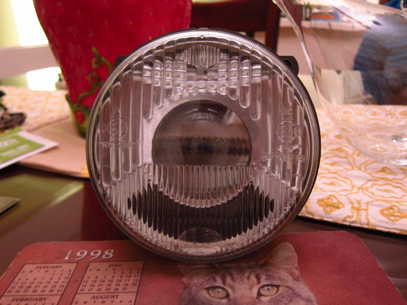
Oh yeah, how sweet is my mouse pad from 1998? Shit's VINTAGE.
Original thread:

As of now, I have one finished adapter plate (out of the two that I will need). The other one will get made over the next couple of weekends. Enough typing though, ain't nobody got time for that. Actually I do, so prepare to get your read on suckas.
I started out by getting my material blanks prepared with the necessary tooling holes. As my father has always said when it comes to cutting ANYTHING, "clamping is everything".
Many cuts later. The digital position readouts on the mill died a while back so this was all run manually the "old school" way...counting ticks/revolutions and doing cuts in only one direction per axis thanks to the ~50 mils of backlash in X & Y lol. I really need to go get some new readouts, manual mode sucks. I got MUCH better results on this one than my first one since I spent a lot more time thinking out the order of operations, and I made a drawing that called out my "tool paths" for each cut so I wasn't trying to subtract cutter diameters in my head while I did it. The first pass on everything left 35 mils of material, then I took off 25 mils and then the final pass was 10 mils on everything. Trying to hog it all out in a single pass is a recipe for crappy surface finish and lousy accuracy.
This was the final operation, and the one that I was most nervous about. Cutting the thing out of the original blank. Clamping was a little challenging just based on cutter clearances and the holes that I left available in the tooling plate (the threaded holes in the pic above). Anyway, it worked out just fine. I stepped through the Z/depth in 6 passes to avoid putting too much force on the clamps in the middle, and then made some light passes to get the diameter right.
Originally, my plan was to make some little cleats that would be screwed to the plastic buckets and then the adapter would screw into those. Well, since I am using much thicker material than originally planned, it became an option to use radial screw connections between the adapter and housing. Much simpler! It will still get sealed with RTV, but I don't trust adhesives enough to just glue the plates on. Here you can see the setup for making the radial mount holes.
Next up were some little spacers. Because I simplified the adapter design to be made as a single-sided milling operation (the original plan involved flipping it over, re-indexing it and machining the second side), I needed some little precision spacers for the FX-R projector bodies.
Finishing one up. I love macro shots lol.
Much to my relief, it fit FLAWLESSLY. No slop, no play, no grinding needed.
In case you were wondering about those radial holes, here's the deal. There are 3 of them (1 at the bottom, 2 about 30° off-center at the top). The screws were just to hold it together for the test-fit and I have some proper ones on order form McMaster.
Those little spacers doing their job here. Note the two open holes in the adapter between the spacers. I'll mention those at the end.
Looking good! There is about ±0.5mm of play available in X & Y for fine-tuning the centering of the lens in the housing / "smiley" trim ring since I used M4 screws and the holes in the projector are 5mm. Mixing inches and millimeters in a design. Fun times. I wish I had metric lead-screws for the mill lol.
Using some countersunk screws to force the projector into alignment with the adapter, the fit is nearly perfect. I may want to nudge it about 10 mils to the left, but then again it doesn't really matter in any functional sense and nobody will ever see (you can't in this picture).
I double-checked the clearance between the lens and projector and there is (a safe) 2mm. There's about 0.5mm between the projector and "smiley" trim ring, so it's dead-on like I wanted.
I will be sealing up the gaps with some high temperature (-30°F to 325°F) weather-proof aluminum tape that I ordered on McMaster. The high-beam solenoid wires are getting run through some weatherproof silicone rubber grommets that will be mounted in the bottom of the plastic headlight bucket.
Those two holes that I mentioned a few pictures above will be used for some little breather vents. They were originally for screw-mounting the adapter to the separate metal cleats that I decided not to make. However, I got super lucky and they are basically the exact right diameter to tap some 10-32 UNF threads into. Why? So I can mount these little breather/filters there!

Moisture is a big concern of mine. The original headlights had breather passages in them to let moisture escape. I am hoping that these little guys will do exactly that while also keeping dust out.
I also ordered a bunch of M4x0.7 fasteners on McMaster that are the exact right length for the various mount holes. The ones holding the adapter to the buckets are button-head types since they are cleaner looking, and the ones holding the projector to the adapter are low-profile socket heads. All black-oxide type too for increased ballerness. Before final installation I am going to see about getting the adapters and spacers anodized some sort of gray color that matches the plastic buckets. Dat OEMness. Hrngggggggg.
Oh yeah, how sweet is my mouse pad from 1998? Shit's VINTAGE.


Comment