-
wow... Take pics of your amp mods. This is crazy and I would love to see what it all looks liek complete.Leave a comment:
-
Time for an update:
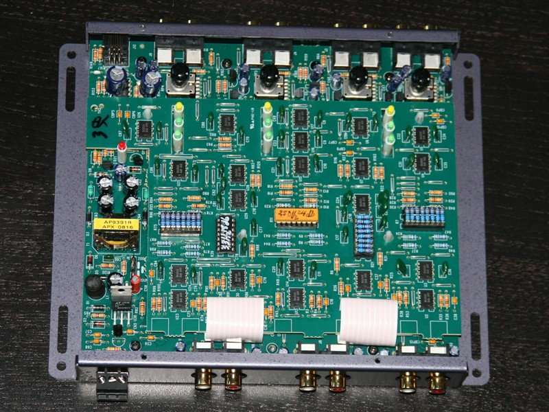
I have spent a good few days reverse-engineering the amplifier's input stages. My main reason for this is bypassing the active filtering on channel 5 since the amp was designed without a bypass for it. CH5 uses a class-D power stage, and this one was only designed to do lower frequency stuff. Since I will be using a higher-order, nicer, external crossover before CH5, I feel that I can safely bypass it. The external cutoff frequency isn't too much higher than the limit on the amp's dial anyway.
I have succeeded in bypassing this and basically jumped the output of the gain-setting op-amp to the input of the final output buffer / RF filter. With 12V powering the amplifier, CH5 is close to clipping with the minimum gain setting and the expected maximum input level from the 6XS. I am going to change out one or two resistors to allow the gain to be adjusted lower than it otherwise would be in the input stage.
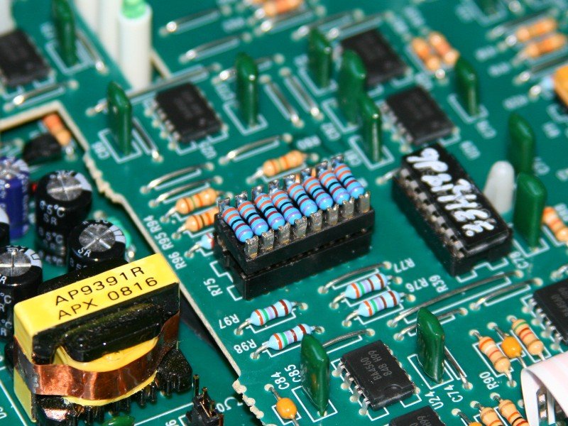
The other order of business will be to install some nicer op-amps. The unit currently uses some STMicro MC4558 units, which are OK for hobby type stuff, but are not really great for audio. Since the power stages probably aren't world-class or anything, I am not going to go dropping serious coin on ridiculous op-amps that headphone enthusiasts like, but I will put in ones with lower noise figures & such. I have ordered some OPA2134's to put in (same pin-outs). They are a good balance of performance and price. You also would not want to put in op-amps with >10MHz bandwidth because there is a lot of high-speed switching circuitry generating RF EMI in there, and you don't want that amplified.
What is the typical battery voltage in an E30 with a good battery when the car is not running? The power rails vary in voltage depending on the input (+/- 23V for Ch1-4 & +/- 41.4V for CH5 with 12V in, +/- 27.3V for Ch1-4 & +/- 48.4V for 14V input). As such, I want to set the gains to be just on the verge of clipping with the lowest reasonable battery voltage present in case I crank it up with the engine off. I am not after absolute maximum power or anything like that...just maximum power under worst-case conditions.
Oh yeah, and once I get the gains dialed in I am removing the potentiometers & putting in regular resistors in their place (of the right value). Cheap pots tend not to hold their setting, especially in an environment like a car, and more-so when mounted near a sub! That, and the dual-pots in there aren't very symmetric, so the gains between CH1/2 & CH3/4 differ a bit for a given position on the pot. Resistors will take care of that.Leave a comment:
-
Wish I could hear this when completed... very nice work.
I've always wanted to go with an active setup, but never had the drive (or cash) to really dive in. Now you've got me looking at the audiocontrol stuff again.Leave a comment:
-
Today's update:
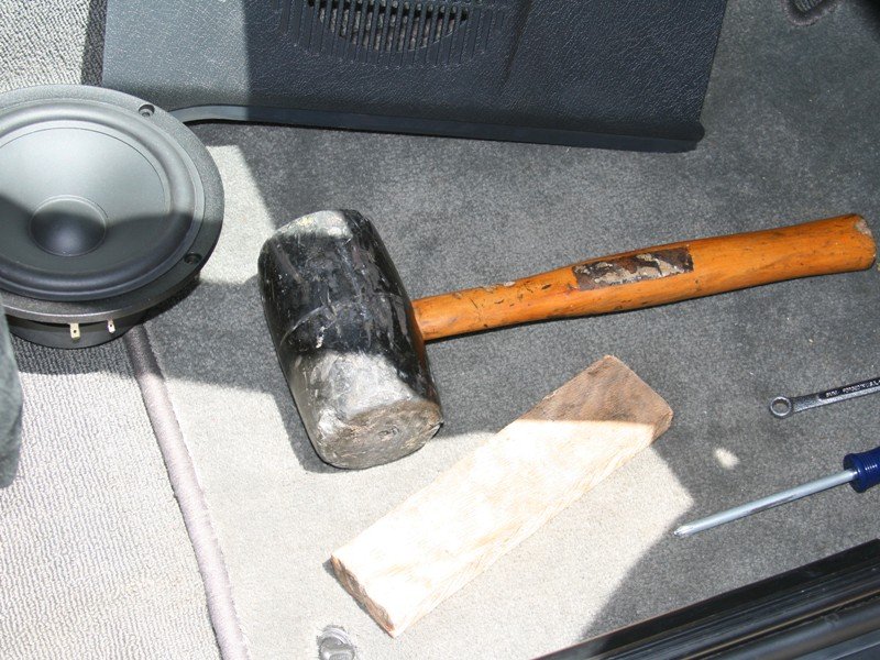
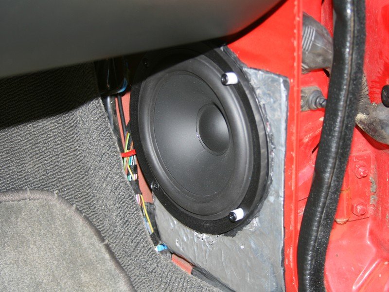
I got the front woofers installed. This was a real bitch. The speaker pods are part of the door jamb, so you really cannot pound the metal out much unless you don't plan to open your door all the way. I plan to open it all the way, so I pounded it out as much as I could without interfering with anything. This bought a few millimeters.
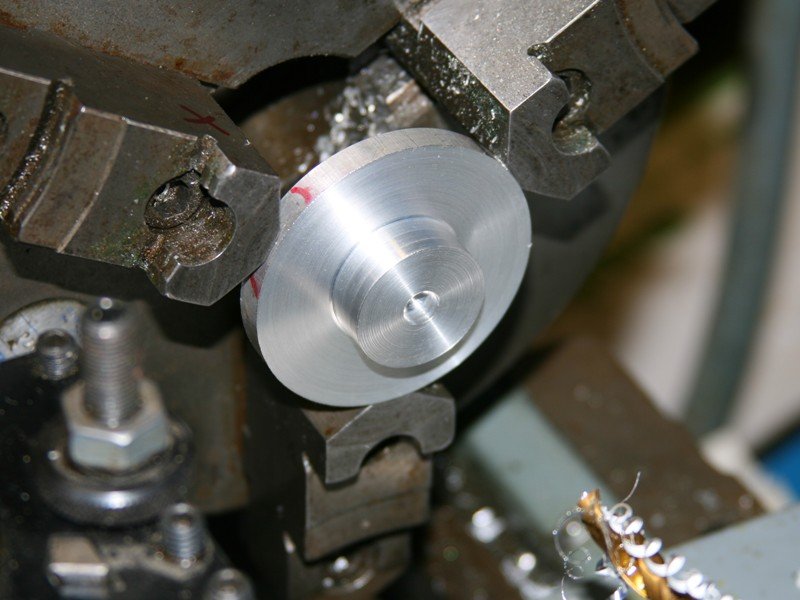
My favorite tool!
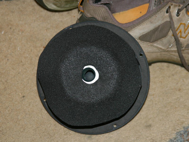
The rear of the pole piece does contact the back of the pod when installed. To avoid buzzing and scraping problems, I put some 1/8" closed cell foam on the back of the drivers. They don't sit completely flat in the back, so the pole piece vent is not blocked off. The foam piece is glued on so it won't go "walking."
Since the surface that they mate to was pulled out a little, and the woofers are reasonably thick, the kick panel cover needs to be spaced out so as not to rest on the cloth surround. I turned out some screw spacers on my trusty lathe from some Delrin bar stock. The cover sits on the screw heads now, and there is Damplifier/foam on the back of it so there is no buzzing. I still need to fasten the front of it (up in the footwell) so that it does not stick out so far into the foot area. I only had to make a minor cut to an edge on the glove box so that it won't scrape on the cover. It is totally out of sight, which is nice.
The driver's side took a bit more work. I chopped off the portion of the kick panel cover that goes under the hood release latch since that wasn't going to fit anymore. I also had to make a small cut-out in the knee bolster cover, which is conveniently out-of-sight. The hood release latch needed to be spaced out to accommodate the new position of the cover, so I made some 10mm Delrin spacers and it works like a fucking charm! I was sweating the installation at first, wondering if I might have to use different drivers, but the BFH (big f*****g hammer) & some fearless chopping got the job done. I will seal their perimeters completely when I run the new signal lines.
Thankfully, that was probably the last of the super tricky stuff. I will be working on the sub baffle & electronic hardware mounting next. I opted to use some cabinet-grade Baltic Birch plywood over MDF for this. Plywood does a lot better with heat & moisture in the long run, and since I am not building an enclosure I don't really need to worry about wall resonance.Last edited by bmwman91; 05-30-2010, 09:38 AM.Leave a comment:
-
Leave a comment:
-
Leave a comment:
-
I have almost all of the parts & hardware now. The supplier of all the marine-grade splices & terminals messed up & sent me fewer connectors than I ordered, so I need to wait for the rest.
Anyway, the plan for the weekend is mainly to mount the amplifier & XO, and to build the sub baffle. I won't be tearing the interior out until I am 100% prepared to do the electrical stuff & knock it all out.
In the spirit of the build, I will be going overboard with the mounting scheme on the electronics. It will be a vibration-isolated setup using some nice neoprene rubber foam blocks. Electronics & vibration don't mix well in the long-run, so I want to make sure everything lives a long & happy life.
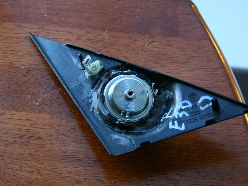
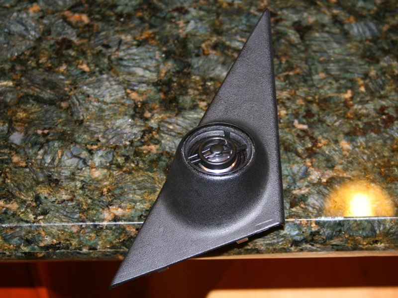
I also got the tweeters done & installed. I had to bend some metal tabs in the door to grab them better, and get creative with a file to get them in right, but they look good now. I still need to find some 1/8" open-celled foam to put under the tweeter grills so that they don't look special to thieves.
Yeah, it is not super clean, but nobody sees it. You can see where I had to get the file out so that the plastic body of the tweeter could clear the door frame.
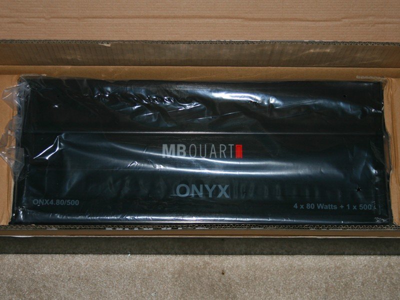
This is the amp. It is big as hell and mounting it will be a chore. Overall, I am totally underwhelmed by it. For $380 it is almost a joke considering the quality of home-amplifiers you can get for $200. The mounting flanges are plastic, the adjustment pots aren't totally straight and one of the warranty stickers was slightly cracked. I was bench-testing it to set the gain earlier, and it is sort of shitty. Ch1 & 2 share a gain potentiometer, and there is a ~12% difference between the channels for any given gain setting (that's a "feature" right, since the right speakers are further away from me?). They should have made adjustment pots for EACH channel.
Here's the amplifier.
The crossover unit at least seems to be of reputable quality. I set the sub/mid LPF at 183Hz, and the HPF for the tweeters is at 2180Hz. Ignore the color bands on the resistors in the pics...they are wrong (as I later found out). It turns out that the "front LPF" part is actually a HPF (that should be set at the same value as the sub LPF), and when coupled with the tweeter HPF (HPF for the tweeter, LPF for the mid) forms a band-pass filter for the mids. The documentation doesn't explain this, probably because it would lead to at least as much confusion. Burn test tones that are solidly in the pass-bands of each filter section & test them. All the planning in the world won't save you if you don't realize you made a mistake. Testing is your friend!
It is very nice that they made the unit in a fashion that allows precise custom settings. I bought a bunch of 0.1% tolerance resistors on DigiKey for this. It is important that the resistors be as close as possible in value to maintain as much noise rejection & phase-coherence as possible.
 Last edited by bmwman91; 11-05-2010, 06:55 PM.
Leave a comment:
-
Amazing installation ! and using the CD43, that will be killer install, looking OEM, Love it ! My dream.
PierreLeave a comment:
-
Today's update:
I finished modifying the tweeters to fit in the pods. It was pretty easy...making the fixture was more work than modding the tweeters lol.
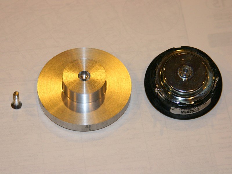
Since putting ferrofluid-filled tweeters into a lathe & spinning them really fast seemed like a bad idea, I decided to make a fixture that would hold them on a rotary table. There the cuts could be made with a mill.
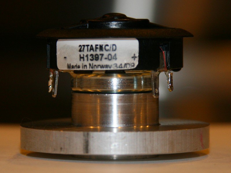
The tweeter is held onto the fixture with an M4x0.7 x 16 machine screw. There is a boss on the back that fits tightly into a bore in the rotary table, thus making it easy to center it on there. I made the jig from a D2.5" 6061 aluminum bar scrap.
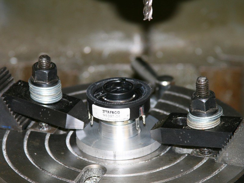
The milling operation was simple. I chopped off the flange and knocked a little material off of the front to a diameter of 38mm so it would fit nicely into the existing tweeter pod hole. Obviously, I didn't want to cut too much off or else the nice diffuser would fall off, and probably end up destroying the dome in the process. I held a shop-vac hose next to the cutter during the process to keep chips out of the thing.
Here they are, all chopped up.
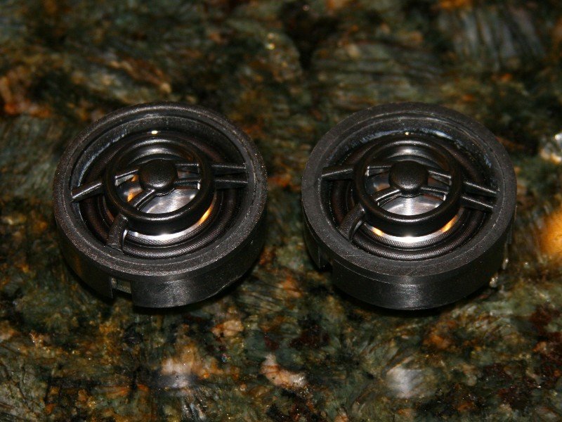
Fitted into the pod...
There is about 2mm of clearance between the diffuser & the grill...perfect! I stuck them in the car and there is like 10mm of extra room behind them. That is good, because I would have been pissed if they weren't going to fit!

Leave a comment:
-
That Kicker can accept a 9VRMS input, you will be fine.
Turn the input gain all the way down when you start tuning.Leave a comment:
-
I have no idea, it depends on the hardware. Unless it specifically states that it (EQ) can accept line-level signals, you shouldn't connect it that way. You can try contacting Kicker to find out what the maximum input voltage is, and if the inputs are grounded or differential. If you have the EQ unit, you can use a DMM to test the impedance between the - input terminal & the ground terminal on it. If the resistance is almost nothing, then you definitely don't want to run both HU outputs to it. The max output from a head unit is probably going to be equal to the battery voltage.
The only LOC I know of is the LC6i, and I haven't used it.Leave a comment:


Leave a comment: