

Admissions first. This is not really a DIY - we will have no completed project at the end, your car won't be faster, won't handle better, won't be sexier, whatever. What this really is, is a guide for the average joe to learn about tackling electronic projects. From wiring audio, radar, electric fans, ect - all these projects use the same set of ideas. The sad truth is a lot of people have a ton of problems with these projects, not because they are unable to fallow instructions, but rather because they dont understand what they are really doing, and as such make mistakes.
These skills - like others worth having - do not appear overnight, I have spent a great deal of time learning about this stuff. The real truth is you dont have to be an electrical engineer, or even an electrician to tackle these project. Kirchhoff's Laws need not apply here.
The point of this write up is to explain a few basic ideas behind tackling electrical projects - both stuff that is well documented and stuff you think of by yourself. I hope you guys enjoy this, I have had a good number of people ask me for something like this over the years, so as I was doing the e39/38 switch conversion it struck me that this is a good time to do this write up. We will loosly use some pictures and ideas from that project.
A local guy who actually gave me the original idea and I talked, He confided in me that he will be a vendor soon on the forum for a plug and play kit for these. For this reason, I have gone back and removed the original planned images and information in this post. It will still convey the information you need to figure out the electronics behind this swap, without giving away the DIY. In fact I encourage you to use that as a good example of a project you can tackle when you master the information in here.
NOTE: Throughout this post I will use words in "" - this implies that while they are common terms, they are generally not accurate. We say if there is voltage flowing to something its getting "power" - this is not accurate but it is a common saying that helps people understand.
If this makes you angry, I am sorry, but i am gonna use it anyway.
First thing is understanding how electricity works - since I am not teaching physics we will keep this relevant to the subject at hand:
Electricity is a form of energy - this means it CANNOT be created or destroyed - it can only change forms. What this really means is for something to work it needs to be a loop. Electricity needs to run in and run out. From now on "Vs" will be our voltage source and GND will be short for ground. Electricity "flows in" at Vs and "flows out" at GND. If GND is not connected, electricity will not flow and nothing will happen.
Before I get into measurements, I want to talk about tools. Our primary tool for stuff like this is a voltmeter. Despite the name this device is capable of measuring a lot of stuff other than voltage.
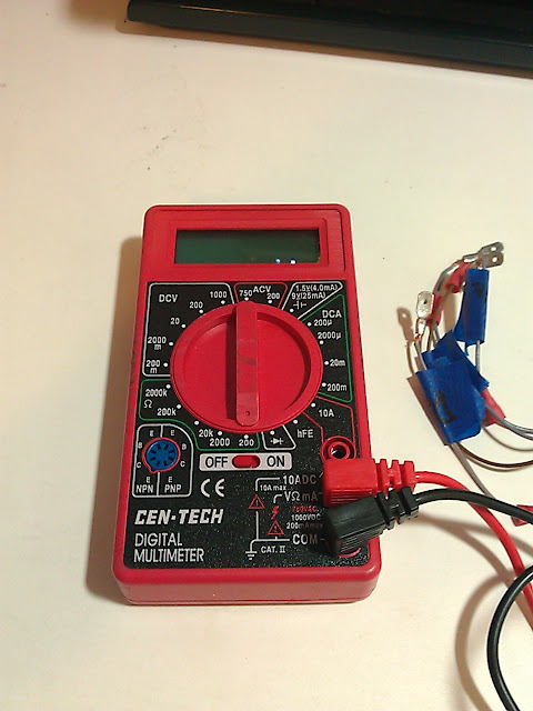
Here is a $3 Voltmeter from Harbor Freight - while it lacks some of the options nicer meters have, it will do just about anything the average hobbyist needs it to do. An excellent investment - I highly recommend buying one.
There are a few interesting measurements we want to know how to take. The first is a voltage measurement, and second is resistance/connectivity.
Voltage measurments measure - you guessed it - voltage. These measurements have to be taken in parallel with what you are trying to measure the voltage across. Say we want to know the voltage flowing into a wire on a switch.
FACT 1: Most cars operate on a 12V DC system. There are exceptions to this rule, but we are going to ignore them.
FACT 2: Ground (where voltage "flows out" is common - what that means is you can ground on just about anything that is grounded. in BMW's a solid brown wire is always a ground. You can also use the frame, body, engine block, ect - since all ground is the same it doesnt matter in this case.
FACT 3: The Red probe goes on the voltage source (Vs) and black probe goes to GND.
FACT 4: Negative voltage implies that the probe is hooked up backwards. In most cases we only care for the absolute value of the voltage, not the sign.
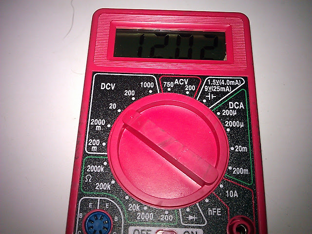
Here we set the dial to the 20V setting - so it will pick up voltage +/- 20V so the 12V system in the car wont have any issue registering.
Here we connect the leads - red to Vs and black to GND
Voltage measurements are useful for figuring out if "power" is flowing to
whatever we are trying to diagnose. So you can see how this can quickly become a very useful tool.
Time for a useful example. What can we do with our ability to use the voltage measurement ability on our voltmeter? Well we can use it to build another useful tool - a power supply. A lot of times it is hot/cold/rainy/shitty outside. so we want to be able to test car parts, projects, run a auto headunit as our reciever in the living room - whatever. This mini DIY will show you how to make one that will output voltage you need, and has a built in breaker that will protect us from frying parts.
Most of the products we use today use 12V, 5v, 3.3V, or 1.8V, there are reasons for these numbers but I wont get into them here. What this tells us is that we really need is a supply that can give us these basic values, or at least a few of these basic values, and we can use them in series, or with a voltage divider to get other values as needed for projects, but more often than nought one of these 4 will do the trick.
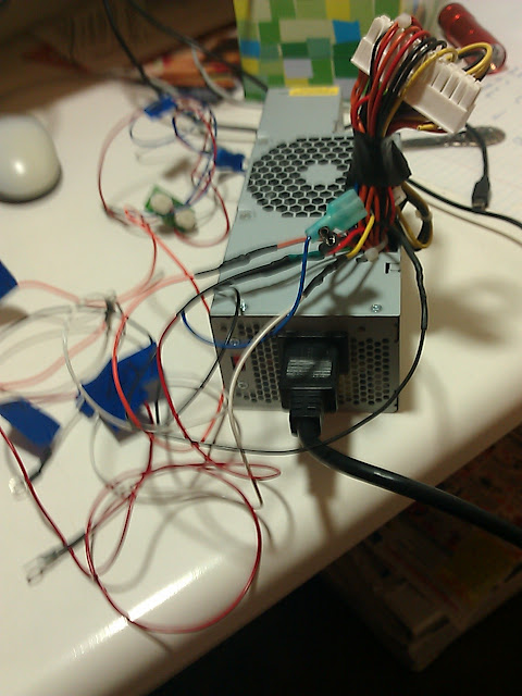
What product produces all these voltages in a cheap, reliable, easy to use device? Sure you could buy DC chargers for each voltage and cut off the wires, but pretty much all of us either have access to old compters, have old computers, or work at a place that does. The first trick is to source an old compter power supply. Now if you plug it into the wall you will soon realize
it does not turn on - it needs a command.
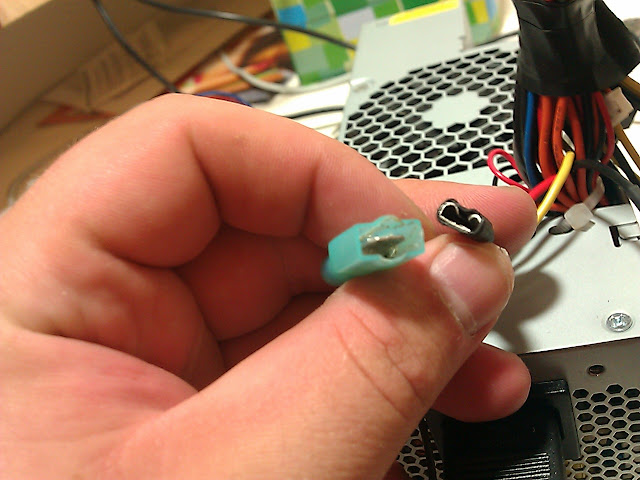
To be able to turn it on and off you need to find the activation wire. It will be in the main harness (2x12 plug) - we are looking for a wire in a color there is only one of. You will see like 6 black wires or so - these are grounds. You will see a lot of repetitive red, orange, yellow wires. Any wire that has two of the same color does not apply here. There should be only 3-4 wires that are single colors. Take a bit of wire from your tool box and touch each of these
to ground in turn, one of them (often green) will trigger the PSU to activate. Once you figure out which wire, simply cut and splice it with a switch or a quick disconnect with one of the grounds:
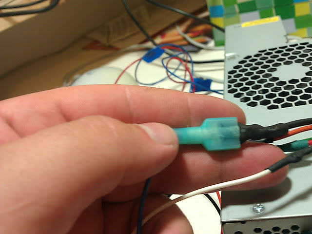
We do this for two reasons - the first is that if we accidently short one of the supplys the internal breaker trips and requires a "restart" so it easier to have a connection we can quickly connect and disconnect.The second reason is safety - you want it to turn off quickly and easily. Now that we have it running its time to find and mark our voltage wires (Vs =12, 5, 3.3, ect).
Take our voltmeter and set it to 20DC volts. Now put one plug to a ground and now use the positive probe to touch a red, yellow, orange, ect wire in turn and write down the result. When you have what you need I recommend extending the lines and adding a quick connect to it. For easy work later. I also recommend spending 3 more dollars at HF and getting a set of gator
clipped wires. Great for this sort of work, and at that price, you can always canabalize them
for projects.
Now we are going to talk about resistance/continuity measurements. First- What is resistance? resistance is basically how hard it is for current to flow through a material. This can be useful for all sorts of electronics, but since this is supposed to be about the basics, we are actually going to focus on continuity. More expensive voltmeters actually have a continuity beeper - this is a great tool as you can use the probes to poke around and when you hear a beep there is electrical continuity. What is electrical continuity? Basically what is being measured is whether or not current can flow between the two probes. So if you have a $3 Harbor Freight voltmeter with no beeper how do we measure continuity?
First we set the dial to measure Resistance. Basically if there is a small <10ohm resistance we have excellent continuity so we set the dial to 200 ohms. In the real world, working with car electronics if the resistance is finite - there is a number - then there is continuity. If the probe shows 0L or a 1 on the left- meaning the resistnace is infinite we have no conductivity.
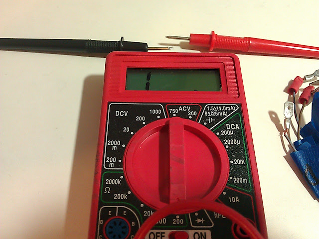
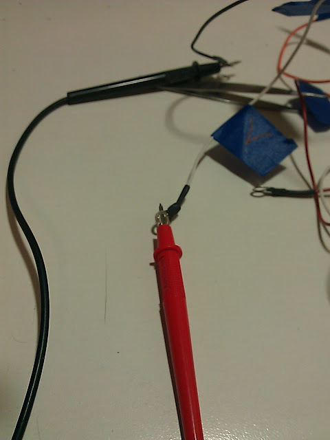
Here the probes are just in the air - no conductivity, notice the reading.
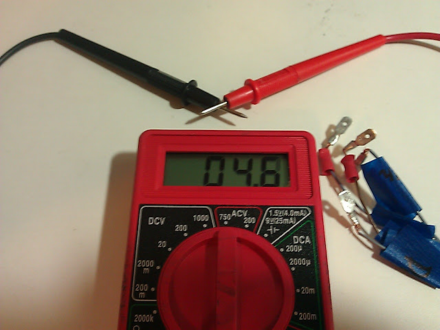
The most basic example is a wire - we know a wire conducts electricity so when we put probes on either end of the wire we quickly see that there is a measureable, finite resistance - this means electricity is flowing.
Another good note I thought I would insert before we got to the methodology. We have different size wires for a reason. That reason is current. How do I read sizes? well the smaller the number the thicker the wire. This is a little counterintuitive but thats just the way it is. 2AWG is huge while 30AWG is a very small wire. So why do the size matter? Current. Think of current as water. If you have a lot of water and you try to push it into a small pipe the pressure (think about resistance!) increases. Eventually the pipe bursts (You burn stuff out!).
So if you are hooking up an e30 window switch -the car runs 12G wire directly to it. This is due to there being 30A of current running through the wire. So you cant hook these two wires together and expect things to work well:
BMW doesnt waste resources, so if its got a thick wire its got a lot of current running though it - so dont attempt to use anthing of a smaller guage. Here are some good reference numbers for wire guage:
30AWG - .09A
22AWG - .9A
18AWG - 2.3A
14AWG - 5.9A
12AWG - 9.3A
10AWG - 15A
4AWG - 60A
2AWG - 94A
**These are for power ratings - the ground ratings are considerably higher, but consider this your worst case scenario.
Ok. Now that we have covered a few basic measurement techiniques and you have the tools to do them, I am going to outline the way I wrap my head around an electronics project. This will kind of walk through how I approach a project that is not documented, and how we figure out what to do. A lot of this is self explanatory - but I think seeing it written out will help people understand how to do these kinds of projects.
This part of the writeup will also included tips/tricks on techniques behind things like soldering and cutting traces, as well as some of the key terminology you need.
First step is pretty self explanatory - we need a goal. In this case the goal was to use an e39 window switch in an e30. We wanted to use the driver side window switch to control both windows or the driver window indipendantly.
I chose the e39 switch since it has two touches - in the e39 the first click lowers the window, and the second click is auto down/up. We want to use touch level 1 to move the e30 driver side window up and down, and touch level 2 to move both driver and passenger window up and down.
Now with goal in mind we can begin.
NOTE: Always keep paper and pen next to you, preferably different color pens. Take notes, its much easier than trying to remember which wire does what later.
Step 1: Think of the device as a black box. No clue whats inside nor do we care, we simply need to figure out if we need to mess with it at all, or maybe it will be plug and play. So lets get a switch and a voltmeter to help us figure out whats going on.

Step 2: We have 4 wires, 4 button positions, that we need to test. We set the voltmeter to resistance as we are really wanting to check continuity. A switch basically opens and closes an electrical connection. We are trying to figure out which wires go "hot" during a certain button combination.
NOTE: In BMW's the solid brown wire is always ground. So we attach the negative lead to the brown wire - this is our drain if you will.
We first try the grey-red wire and find that no button combination causes continuity. We know that inside there is a LED light (it shines at night) so this must be the "power" or Vs connection for teh LED. Since it is a diode, it wont conduct until a certain voltage is applied to it. We mark the wire on our paper and move on.
Now we move to the next wire. We find that it conducts in the certain combination. Now we move to the last wire. We read conductivity.
Before we move on to the inside of the switch, let take a look at the logic. currrently we have 4 wires. One is a ground. The grey-red wire is believed to be the LED, we will confirm this later, but we plan on wiring to the LED wire in the car. Lets operate for now on the idea that we are rightin our assumption.
What do we really need? We need one wire to trigger driver down, driver up, both down, both up -
4 connection, and we currently have two wires. So we already know we will be creating at least two new connections.
So now we take a peek inside that black box of ours. I used a small flathead to pry it apart and pull out the ICB out. ICB = integrated circuit board - its that green thing with the components attached. Now that we have it remove we can begin to study it.

Some information can be gained from visible traces - traces are the little lines on the board. The green cover hides a copper conduit that passes electricity from point to point. Lets first confirm our believe about the LED. We can now see that pin 2 (G/R) runs to the LED, so we know we were right about its function.
I like the shotgun approach - especially when a schematic for the board or the switches is not readily available. So we flip it upsidedown so all the nodes are open for inspection. Attached the black probe to ground, and start measuring conductivity. I like to take a picture and then go through and label all the nodes as to what they are conductive to, and put it all in the picture as i go.
Now that we know what everything does, we start thinking about what we want to isolate. So remember we need U1, U2, D1, D2, all on seperate wires. Or rather we simply need a seperate way of activating D2 and U2 without triggering D1, or U1.
Sometimes we can cut a trace - like removing digital logic, so that a single node only connects to one input.
CUTTING TRACES: The trick is to use an exacto knife, and gently scrape of the green covering, and then make one good sharp cut. You can use what we know about conductivity to make sure the cut we made was good.


So lets go and see whats going on in the car! You have a voltmeter. Set it to 20V and pull the stock e30 switch harness up out of the center consol.Make sure the switch stays attached. Flip it over and pull the cover.
Now we simply measure the voltage accross th individual wires and the ground while pushing the up and down switches. When we get a voltage we know
what that line means.
Here is what you should come up with:
Purple - Down
Black - Up
Green - LED
Brown - Ground
Now there are a few more steps to get this working - I am going to leave these to you to figure out. There is a guy on here selling plug and play kits, and out of respect to him I wont give you the complete solution. However if you want to double check a plan of action with me, I will be more than happy to help you as long as you dont just ask me for the answer.
Congratulations, you completed a electronic project that there was no documentation for. You figured it all out piece by piece, and can now use these skills to complete more and more complex projects. Thanks for reading all the way down through this, and Good Luck!
PS: If anyone has any cool ideas they want to see worked out, I would be more than happy to do them to see if I cant get them to work. Just shoot me a PM.
These skills - like others worth having - do not appear overnight, I have spent a great deal of time learning about this stuff. The real truth is you dont have to be an electrical engineer, or even an electrician to tackle these project. Kirchhoff's Laws need not apply here.
The point of this write up is to explain a few basic ideas behind tackling electrical projects - both stuff that is well documented and stuff you think of by yourself. I hope you guys enjoy this, I have had a good number of people ask me for something like this over the years, so as I was doing the e39/38 switch conversion it struck me that this is a good time to do this write up. We will loosly use some pictures and ideas from that project.
A local guy who actually gave me the original idea and I talked, He confided in me that he will be a vendor soon on the forum for a plug and play kit for these. For this reason, I have gone back and removed the original planned images and information in this post. It will still convey the information you need to figure out the electronics behind this swap, without giving away the DIY. In fact I encourage you to use that as a good example of a project you can tackle when you master the information in here.
NOTE: Throughout this post I will use words in "" - this implies that while they are common terms, they are generally not accurate. We say if there is voltage flowing to something its getting "power" - this is not accurate but it is a common saying that helps people understand.
If this makes you angry, I am sorry, but i am gonna use it anyway.
First thing is understanding how electricity works - since I am not teaching physics we will keep this relevant to the subject at hand:
Electricity is a form of energy - this means it CANNOT be created or destroyed - it can only change forms. What this really means is for something to work it needs to be a loop. Electricity needs to run in and run out. From now on "Vs" will be our voltage source and GND will be short for ground. Electricity "flows in" at Vs and "flows out" at GND. If GND is not connected, electricity will not flow and nothing will happen.
Before I get into measurements, I want to talk about tools. Our primary tool for stuff like this is a voltmeter. Despite the name this device is capable of measuring a lot of stuff other than voltage.
Here is a $3 Voltmeter from Harbor Freight - while it lacks some of the options nicer meters have, it will do just about anything the average hobbyist needs it to do. An excellent investment - I highly recommend buying one.
There are a few interesting measurements we want to know how to take. The first is a voltage measurement, and second is resistance/connectivity.
Voltage measurments measure - you guessed it - voltage. These measurements have to be taken in parallel with what you are trying to measure the voltage across. Say we want to know the voltage flowing into a wire on a switch.
FACT 1: Most cars operate on a 12V DC system. There are exceptions to this rule, but we are going to ignore them.
FACT 2: Ground (where voltage "flows out" is common - what that means is you can ground on just about anything that is grounded. in BMW's a solid brown wire is always a ground. You can also use the frame, body, engine block, ect - since all ground is the same it doesnt matter in this case.
FACT 3: The Red probe goes on the voltage source (Vs) and black probe goes to GND.
FACT 4: Negative voltage implies that the probe is hooked up backwards. In most cases we only care for the absolute value of the voltage, not the sign.
Here we set the dial to the 20V setting - so it will pick up voltage +/- 20V so the 12V system in the car wont have any issue registering.
Here we connect the leads - red to Vs and black to GND
Voltage measurements are useful for figuring out if "power" is flowing to
whatever we are trying to diagnose. So you can see how this can quickly become a very useful tool.
Time for a useful example. What can we do with our ability to use the voltage measurement ability on our voltmeter? Well we can use it to build another useful tool - a power supply. A lot of times it is hot/cold/rainy/shitty outside. so we want to be able to test car parts, projects, run a auto headunit as our reciever in the living room - whatever. This mini DIY will show you how to make one that will output voltage you need, and has a built in breaker that will protect us from frying parts.
Most of the products we use today use 12V, 5v, 3.3V, or 1.8V, there are reasons for these numbers but I wont get into them here. What this tells us is that we really need is a supply that can give us these basic values, or at least a few of these basic values, and we can use them in series, or with a voltage divider to get other values as needed for projects, but more often than nought one of these 4 will do the trick.
What product produces all these voltages in a cheap, reliable, easy to use device? Sure you could buy DC chargers for each voltage and cut off the wires, but pretty much all of us either have access to old compters, have old computers, or work at a place that does. The first trick is to source an old compter power supply. Now if you plug it into the wall you will soon realize
it does not turn on - it needs a command.
To be able to turn it on and off you need to find the activation wire. It will be in the main harness (2x12 plug) - we are looking for a wire in a color there is only one of. You will see like 6 black wires or so - these are grounds. You will see a lot of repetitive red, orange, yellow wires. Any wire that has two of the same color does not apply here. There should be only 3-4 wires that are single colors. Take a bit of wire from your tool box and touch each of these
to ground in turn, one of them (often green) will trigger the PSU to activate. Once you figure out which wire, simply cut and splice it with a switch or a quick disconnect with one of the grounds:
We do this for two reasons - the first is that if we accidently short one of the supplys the internal breaker trips and requires a "restart" so it easier to have a connection we can quickly connect and disconnect.The second reason is safety - you want it to turn off quickly and easily. Now that we have it running its time to find and mark our voltage wires (Vs =12, 5, 3.3, ect).
Take our voltmeter and set it to 20DC volts. Now put one plug to a ground and now use the positive probe to touch a red, yellow, orange, ect wire in turn and write down the result. When you have what you need I recommend extending the lines and adding a quick connect to it. For easy work later. I also recommend spending 3 more dollars at HF and getting a set of gator
clipped wires. Great for this sort of work, and at that price, you can always canabalize them
for projects.
Now we are going to talk about resistance/continuity measurements. First- What is resistance? resistance is basically how hard it is for current to flow through a material. This can be useful for all sorts of electronics, but since this is supposed to be about the basics, we are actually going to focus on continuity. More expensive voltmeters actually have a continuity beeper - this is a great tool as you can use the probes to poke around and when you hear a beep there is electrical continuity. What is electrical continuity? Basically what is being measured is whether or not current can flow between the two probes. So if you have a $3 Harbor Freight voltmeter with no beeper how do we measure continuity?
First we set the dial to measure Resistance. Basically if there is a small <10ohm resistance we have excellent continuity so we set the dial to 200 ohms. In the real world, working with car electronics if the resistance is finite - there is a number - then there is continuity. If the probe shows 0L or a 1 on the left- meaning the resistnace is infinite we have no conductivity.
Here the probes are just in the air - no conductivity, notice the reading.
The most basic example is a wire - we know a wire conducts electricity so when we put probes on either end of the wire we quickly see that there is a measureable, finite resistance - this means electricity is flowing.
Another good note I thought I would insert before we got to the methodology. We have different size wires for a reason. That reason is current. How do I read sizes? well the smaller the number the thicker the wire. This is a little counterintuitive but thats just the way it is. 2AWG is huge while 30AWG is a very small wire. So why do the size matter? Current. Think of current as water. If you have a lot of water and you try to push it into a small pipe the pressure (think about resistance!) increases. Eventually the pipe bursts (You burn stuff out!).
So if you are hooking up an e30 window switch -the car runs 12G wire directly to it. This is due to there being 30A of current running through the wire. So you cant hook these two wires together and expect things to work well:
BMW doesnt waste resources, so if its got a thick wire its got a lot of current running though it - so dont attempt to use anthing of a smaller guage. Here are some good reference numbers for wire guage:
30AWG - .09A
22AWG - .9A
18AWG - 2.3A
14AWG - 5.9A
12AWG - 9.3A
10AWG - 15A
4AWG - 60A
2AWG - 94A
**These are for power ratings - the ground ratings are considerably higher, but consider this your worst case scenario.
Ok. Now that we have covered a few basic measurement techiniques and you have the tools to do them, I am going to outline the way I wrap my head around an electronics project. This will kind of walk through how I approach a project that is not documented, and how we figure out what to do. A lot of this is self explanatory - but I think seeing it written out will help people understand how to do these kinds of projects.
This part of the writeup will also included tips/tricks on techniques behind things like soldering and cutting traces, as well as some of the key terminology you need.
First step is pretty self explanatory - we need a goal. In this case the goal was to use an e39 window switch in an e30. We wanted to use the driver side window switch to control both windows or the driver window indipendantly.
I chose the e39 switch since it has two touches - in the e39 the first click lowers the window, and the second click is auto down/up. We want to use touch level 1 to move the e30 driver side window up and down, and touch level 2 to move both driver and passenger window up and down.
Now with goal in mind we can begin.
NOTE: Always keep paper and pen next to you, preferably different color pens. Take notes, its much easier than trying to remember which wire does what later.
Step 1: Think of the device as a black box. No clue whats inside nor do we care, we simply need to figure out if we need to mess with it at all, or maybe it will be plug and play. So lets get a switch and a voltmeter to help us figure out whats going on.
Step 2: We have 4 wires, 4 button positions, that we need to test. We set the voltmeter to resistance as we are really wanting to check continuity. A switch basically opens and closes an electrical connection. We are trying to figure out which wires go "hot" during a certain button combination.
NOTE: In BMW's the solid brown wire is always ground. So we attach the negative lead to the brown wire - this is our drain if you will.
We first try the grey-red wire and find that no button combination causes continuity. We know that inside there is a LED light (it shines at night) so this must be the "power" or Vs connection for teh LED. Since it is a diode, it wont conduct until a certain voltage is applied to it. We mark the wire on our paper and move on.
Now we move to the next wire. We find that it conducts in the certain combination. Now we move to the last wire. We read conductivity.
Before we move on to the inside of the switch, let take a look at the logic. currrently we have 4 wires. One is a ground. The grey-red wire is believed to be the LED, we will confirm this later, but we plan on wiring to the LED wire in the car. Lets operate for now on the idea that we are rightin our assumption.
What do we really need? We need one wire to trigger driver down, driver up, both down, both up -
4 connection, and we currently have two wires. So we already know we will be creating at least two new connections.
So now we take a peek inside that black box of ours. I used a small flathead to pry it apart and pull out the ICB out. ICB = integrated circuit board - its that green thing with the components attached. Now that we have it remove we can begin to study it.
Some information can be gained from visible traces - traces are the little lines on the board. The green cover hides a copper conduit that passes electricity from point to point. Lets first confirm our believe about the LED. We can now see that pin 2 (G/R) runs to the LED, so we know we were right about its function.
I like the shotgun approach - especially when a schematic for the board or the switches is not readily available. So we flip it upsidedown so all the nodes are open for inspection. Attached the black probe to ground, and start measuring conductivity. I like to take a picture and then go through and label all the nodes as to what they are conductive to, and put it all in the picture as i go.
Now that we know what everything does, we start thinking about what we want to isolate. So remember we need U1, U2, D1, D2, all on seperate wires. Or rather we simply need a seperate way of activating D2 and U2 without triggering D1, or U1.
Sometimes we can cut a trace - like removing digital logic, so that a single node only connects to one input.
CUTTING TRACES: The trick is to use an exacto knife, and gently scrape of the green covering, and then make one good sharp cut. You can use what we know about conductivity to make sure the cut we made was good.
So lets go and see whats going on in the car! You have a voltmeter. Set it to 20V and pull the stock e30 switch harness up out of the center consol.Make sure the switch stays attached. Flip it over and pull the cover.
Now we simply measure the voltage accross th individual wires and the ground while pushing the up and down switches. When we get a voltage we know
what that line means.
Here is what you should come up with:
Purple - Down
Black - Up
Green - LED
Brown - Ground
Now there are a few more steps to get this working - I am going to leave these to you to figure out. There is a guy on here selling plug and play kits, and out of respect to him I wont give you the complete solution. However if you want to double check a plan of action with me, I will be more than happy to help you as long as you dont just ask me for the answer.
Congratulations, you completed a electronic project that there was no documentation for. You figured it all out piece by piece, and can now use these skills to complete more and more complex projects. Thanks for reading all the way down through this, and Good Luck!
PS: If anyone has any cool ideas they want to see worked out, I would be more than happy to do them to see if I cant get them to work. Just shoot me a PM.

Comment