
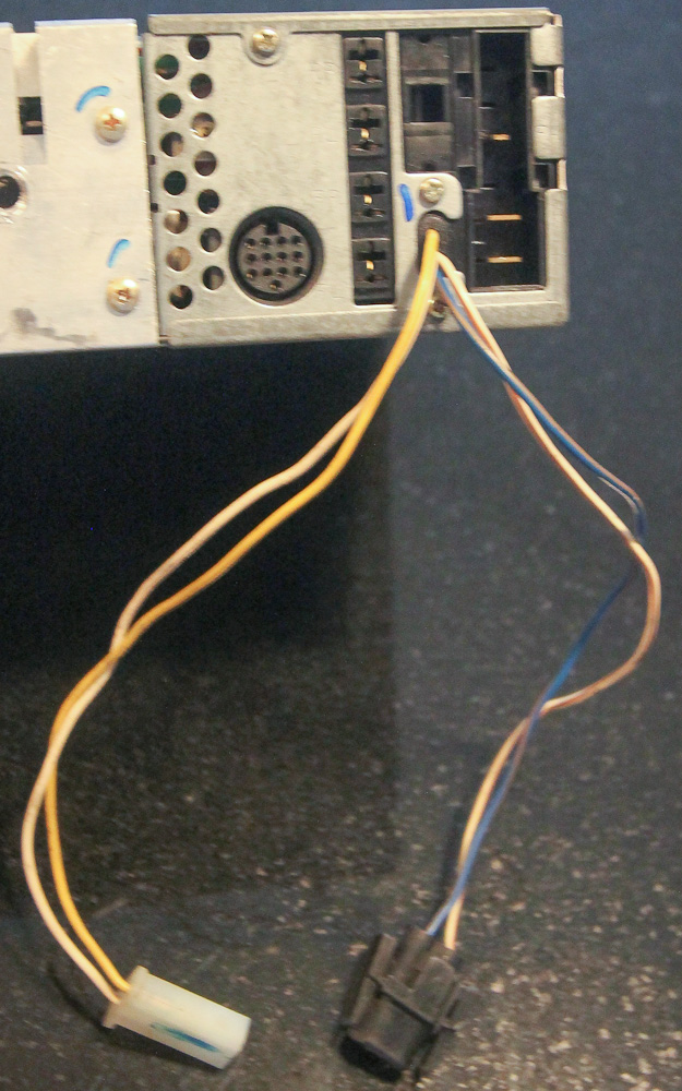
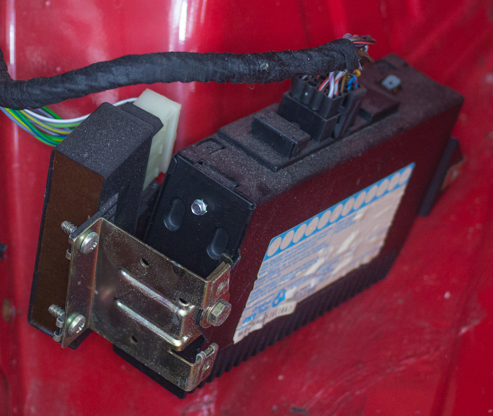
I've decided to put an aftermarket stereo in my '90 M3 (in the glovebox) with premium sound, and in the process pulled the factory unit out. The late-model E30 had the "Pyramid" stereo (Alpine CM5908). The audio outputs are routed through the big black connector such that I don't think I'll have to cut any wires in the harness. I found some wiring info here. I think it will be slightly different for each model depending on vintage and the existence of a factory amp.
Here are some photos I took along the way:


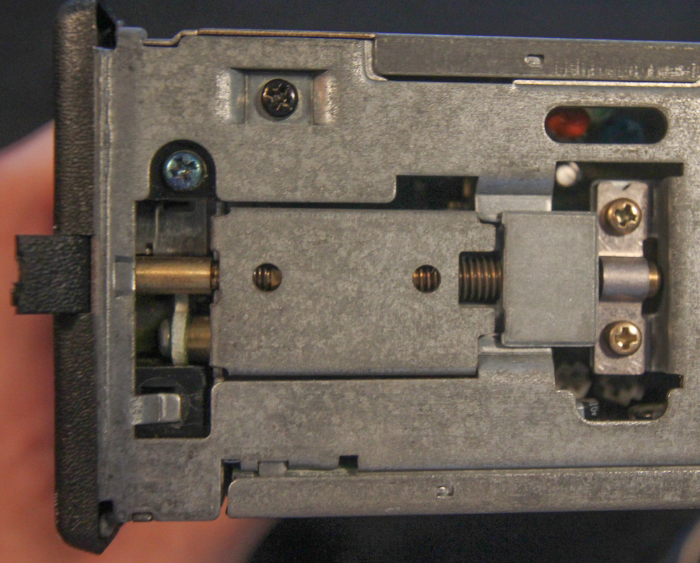
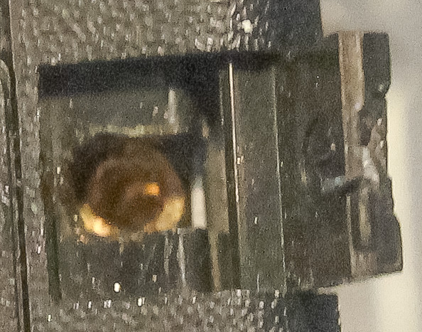
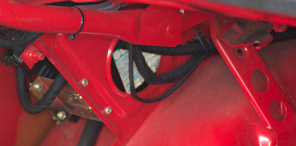
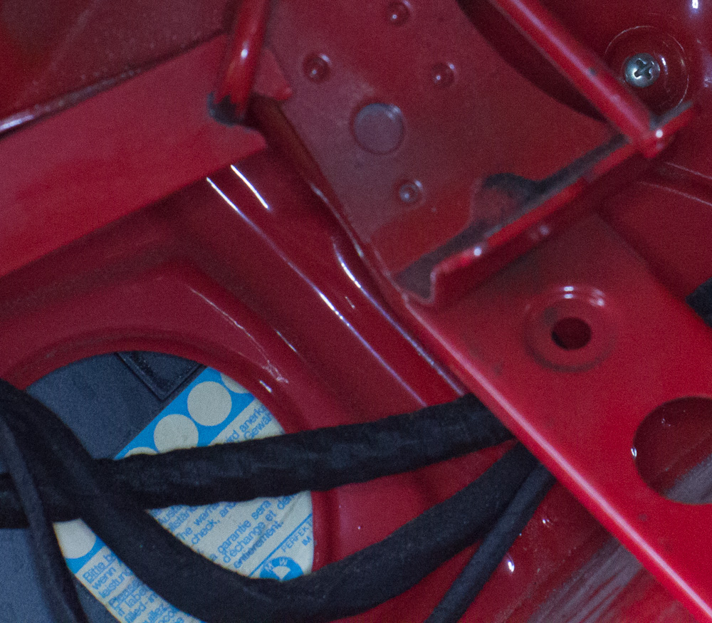
Here are some shots of the screw mechanism that holds the head unit in. I used a pointy knife to open the plastic tab, then a 5/64 allen key to unscrew the mechanism. It doesn't fit perfectly; you may need to insert it at a bit of an angle to get a better purchase inside the screw.
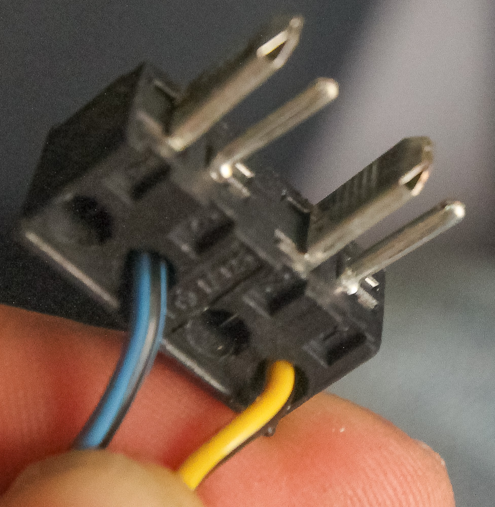
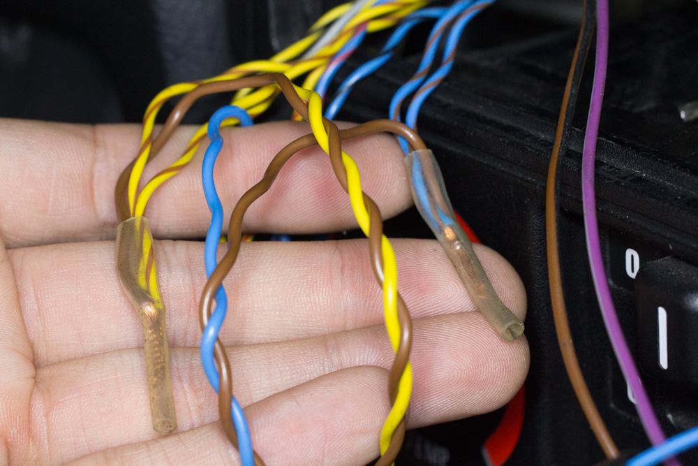
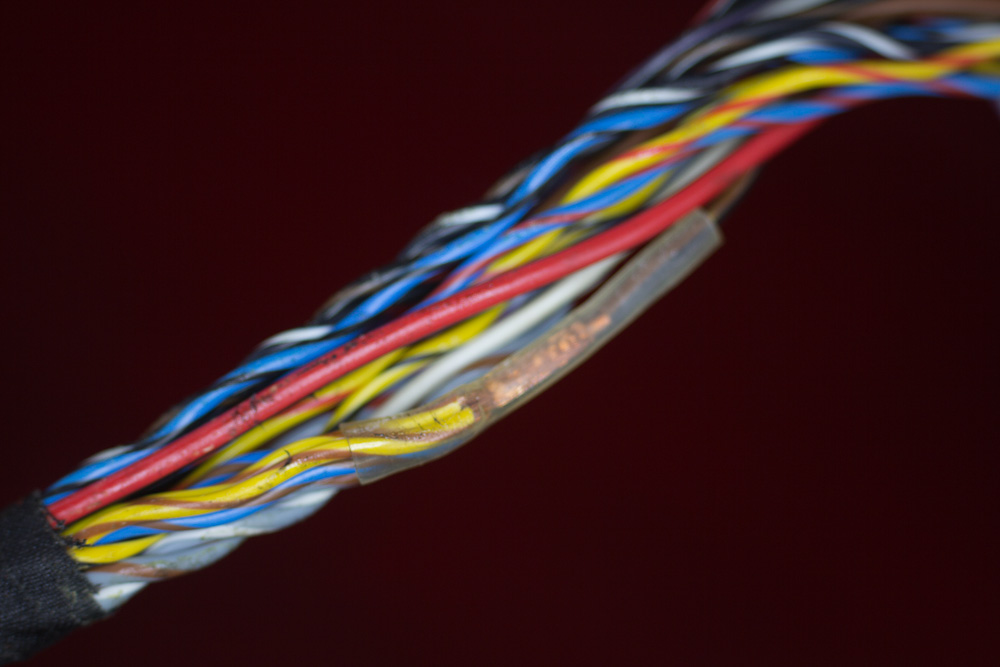
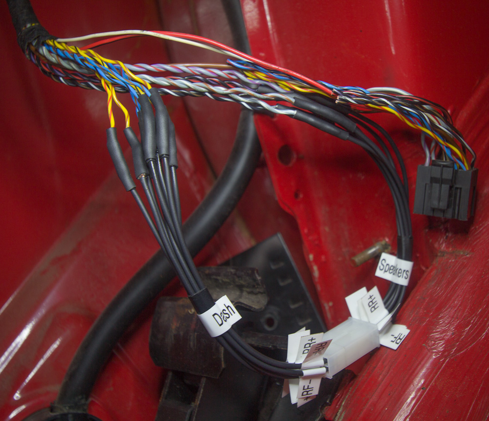
Here's a shot of the back of the big black connector...The interesting bit is the re-routing of some of the audio audio outs.

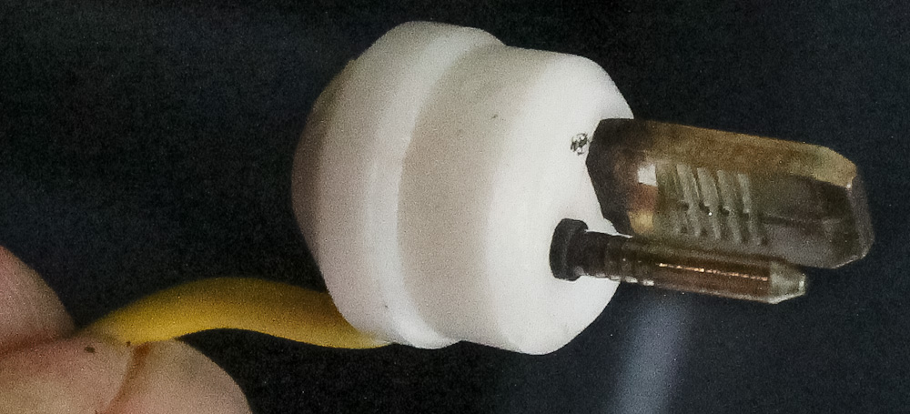
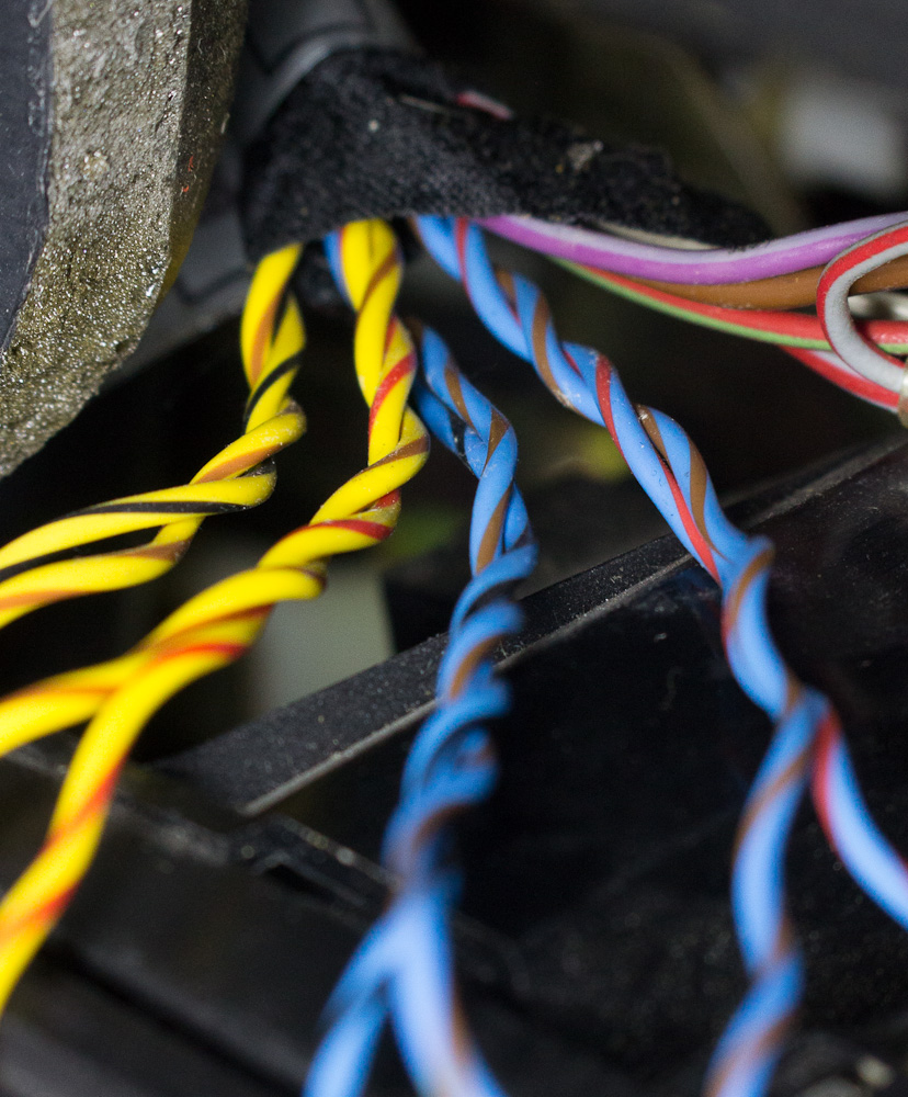
Another shot of the black connector, this time the side that's in the car. You'll notice that some wires simply aren't attached to anything on the other side of the connector.

Speakers - Early
Front
LF - Yellow/Yellow & Brown - +/- [The yellow twisted pair at connector C212]
RF - Blue/Blue & Brown - +/- [The blue twisted pair at connector C218]
Rear
LR & RR - Yellow & Black/Blue & Black - +/+ [The blue and yellow pair at connector C244. The minus connection for these speakers is in a splice to the LF and RF minus wires.]
Speakers - Late
Front
LF - Yellow & Red/Yellow & Gray - +/- [The yellow twisted pair at connector C212]
RF - Blue & Red/Blue & Gray - +/- [The blue twisted pair at connector C218]
Rear
LF - Yellow & Black/Yellow & Brown- +/- [The yellow twisted pair at connector C245]
RF - Blue & Black/Blue & Brown- +/- [The blue twisted pair at connector C244]
Others
The White and Yellow pair ending at C215
White is the lights on input and connects to a Gray & Red wire at the connector.
Yellow is constant power and connects to a Red & Green wire at the connector.
The single White wire is the antenna up [and amp on if yours had one] output.
I'm having a hard time seeing the exact color of the remaining unconnected bundle but I think it's the switched power and ground connection. See if these colors match up.
Violet & Gray - switched power
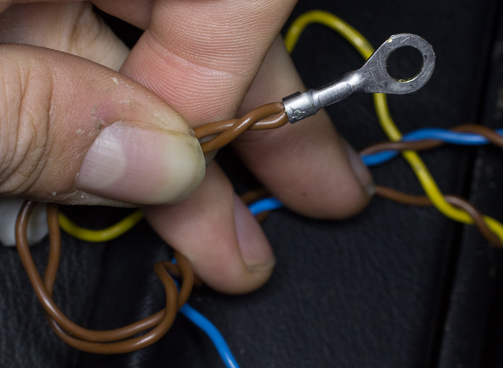
Brown - Chassis ground
One final thing to remember. If the radio has lost power, you'll need the radio code to input.
Front
LF - Yellow/Yellow & Brown - +/- [The yellow twisted pair at connector C212]
RF - Blue/Blue & Brown - +/- [The blue twisted pair at connector C218]
Rear
LR & RR - Yellow & Black/Blue & Black - +/+ [The blue and yellow pair at connector C244. The minus connection for these speakers is in a splice to the LF and RF minus wires.]
Speakers - Late
Front
LF - Yellow & Red/Yellow & Gray - +/- [The yellow twisted pair at connector C212]
RF - Blue & Red/Blue & Gray - +/- [The blue twisted pair at connector C218]
Rear
LF - Yellow & Black/Yellow & Brown- +/- [The yellow twisted pair at connector C245]
RF - Blue & Black/Blue & Brown- +/- [The blue twisted pair at connector C244]
Others
The White and Yellow pair ending at C215
White is the lights on input and connects to a Gray & Red wire at the connector.
Yellow is constant power and connects to a Red & Green wire at the connector.
The single White wire is the antenna up [and amp on if yours had one] output.
I'm having a hard time seeing the exact color of the remaining unconnected bundle but I think it's the switched power and ground connection. See if these colors match up.
Violet & Gray - switched power
Brown - Chassis ground
One final thing to remember. If the radio has lost power, you'll need the radio code to input.
Here are some shots of the screw mechanism that holds the head unit in. I used a pointy knife to open the plastic tab, then a 5/64 allen key to unscrew the mechanism. It doesn't fit perfectly; you may need to insert it at a bit of an angle to get a better purchase inside the screw.
Here's a shot of the back of the big black connector...The interesting bit is the re-routing of some of the audio audio outs.
Another shot of the black connector, this time the side that's in the car. You'll notice that some wires simply aren't attached to anything on the other side of the connector.


Comment