-
Yes, you got it right. Let's wait for blackspeed though, I don't trust my memory -
Luke, can you confirm that I have things right?
Large red/white wire is constant 12V from battery.
Smaller red wire is switched 12V from ignition.
The SAFE pin should be connected to the switched 12V from ignition.
Also, it looks like you can turn the unit on when the ignition is OFF...which seems less than ideal. If I have just the large red/white wire powered with 12V, I can turn the unit on and off with the power button. Please tell me I am overlooking something!Last edited by bmwman91; 11-06-2014, 04:49 PM.Leave a comment:
-
That's an idea. I haven't worked with CANBUS stuff before, but I bet the VW protocols are out there on the web somewhere. Controls on the steering wheel would be pretty sweet.Leave a comment:
-
I forgot to mention...the remote wire stays live for about 30 seconds after power off...
Oh yeah, I see CANBUS terminals too...wonder if this thing could be made to use steering wheel controls?Leave a comment:
-
Everyone has to start somewhere! Not too many years ago, I knew exactly jack shit about electronics and audio. All of the information is out there on the web, granted it is damn hard to "know where to start" and it can be overwhelming, but if you jump in you'll learn to swim one way or another. Granted, I have been lucky to have some smart people that know electrical engineering to help guide me to get me going, so that always helps.
A couple of quick updates.
- I was looking through a schematic that I had found for the JCV head unit that I wanted to put the CD43 faceplate on and it uses the exact same DSP chip as the RMT200. This helps me tremendously, particularly since it has a full 5V pre-amp circuit, so I will probably base my design on that!
- The big amp IC does all sorts of stuff, including having all the various voltage regulators for basically everything on the board built in. It ALSO has a switched 12V output for amplifiers on pin 29. I am not sure what it is connected to exactly, but it is there and it turns on and off with the amp and can probably be used for an amp/antenna signal. This does mean that the big IC can't be removed, but that's fine.Last edited by bmwman91; 11-06-2014, 12:23 PM.Leave a comment:
-
i love doing stuff like this. too bad i don't know what i am doing.Leave a comment:
-
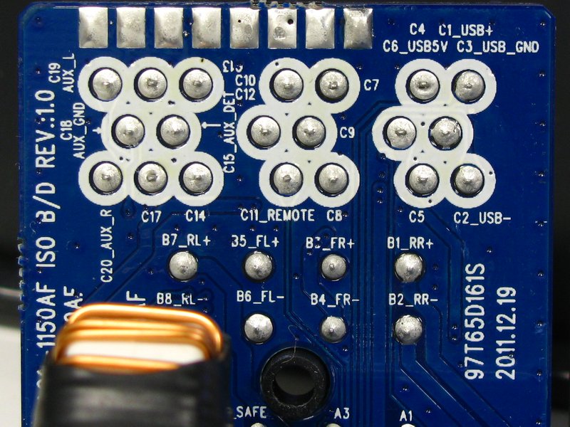
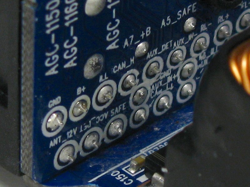
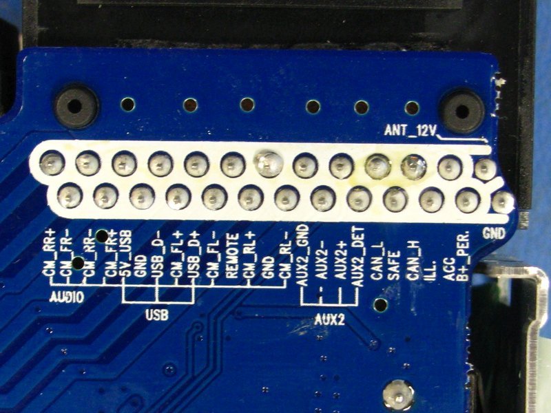
OK, time for some more pics. These may not be as interesting, but they are here just for detail's sake in case people want to know what specific connections are available. Some of these are similar to those in the OP, except this time they should be a lot cleaner since I had a little desktop tripod for the camera (instead of shaky, caffeinated hands).
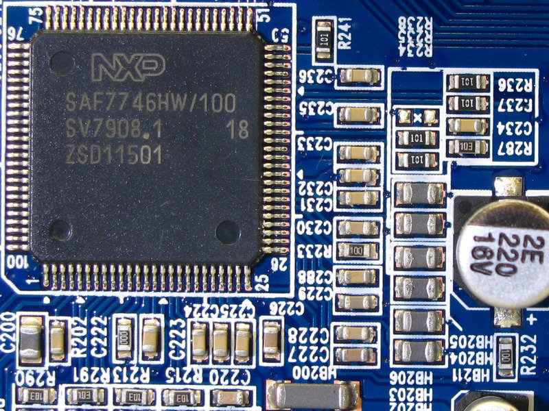
A close-up of the area around the DSP chip where the 4 audio outputs are. The outputs have very few components on them (lots in the photo, only a few are for the audio output lines). One of the signal lines goes out from the DSP to C231 (and the other side of C231 is ground) and continues to HB205 (top-most gray thing of the 6 you see lined up there), and then across the board to C513 (not shown in photo) and through that to pin 15 of the amp IC (one of the 4 inputs). The other 3 outputs are connected in the same way to the other nearby components.
One other thing I did was "clean up" the harness that I ordered with the unit. I removed the male terminals from the big VW OEM connector. If you look down the bores, you can sort of see that the terminals just have one locking tongue.
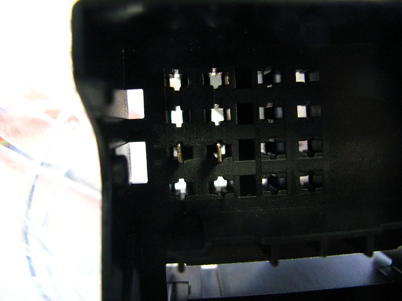
Use a paperclip or probe or something to depress the locking tongue, and you can pull the terminal right out.
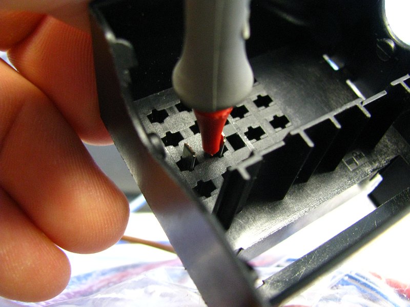
The white "accessory" connector can also be removed super easily by just prying the 2 side locking tabs.
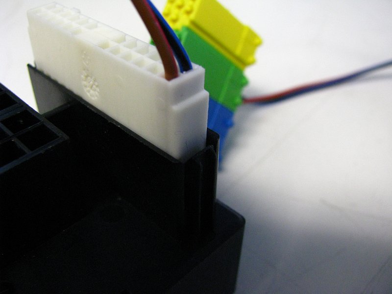
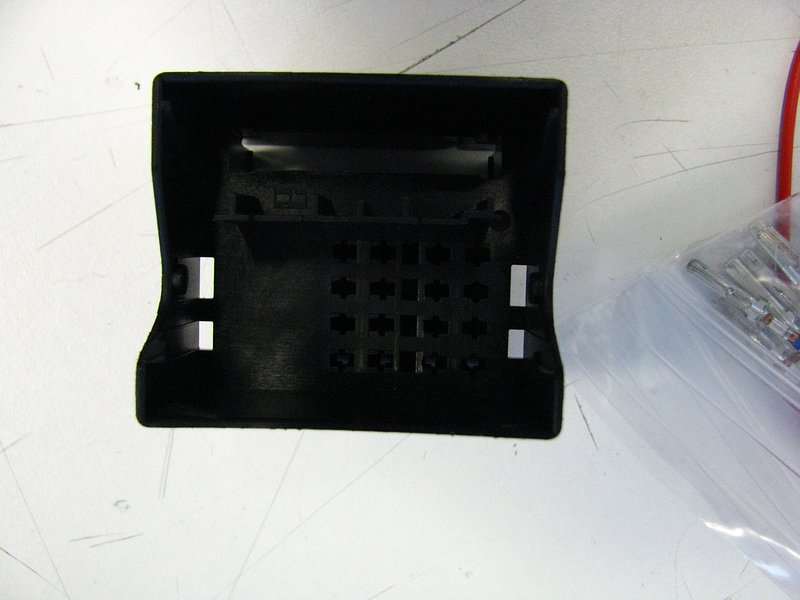
And there you go, an empty VW radio connector to feed to your trash.
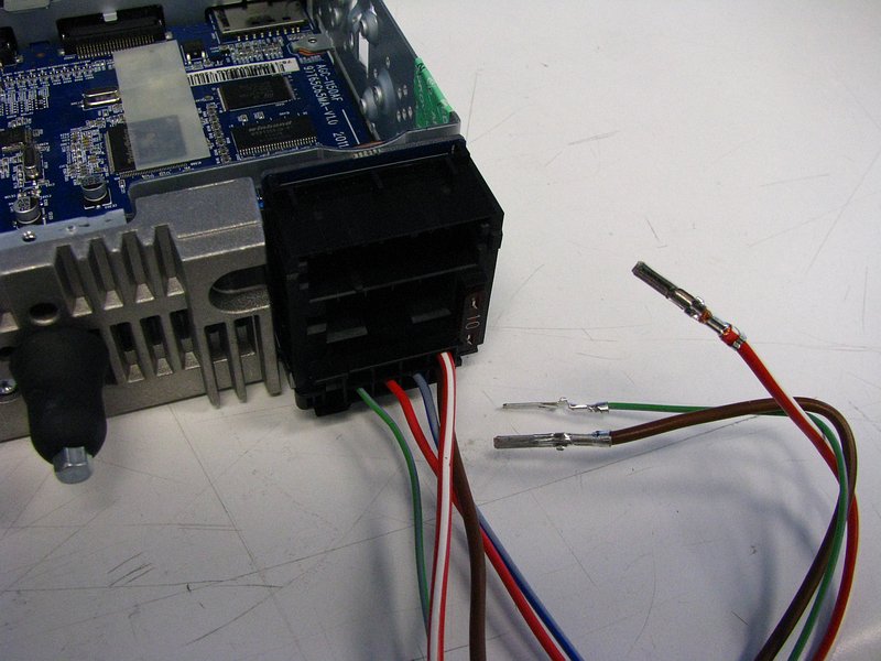
With that taken care of, you will have wires to mess with. The last steps were 100% unnecessary since you will be chopping those terminals off anyway so you can splice this into your E30, but I figured I would show the process. For bench-testing, I am making use of those crimped terminals.
Continuing on...
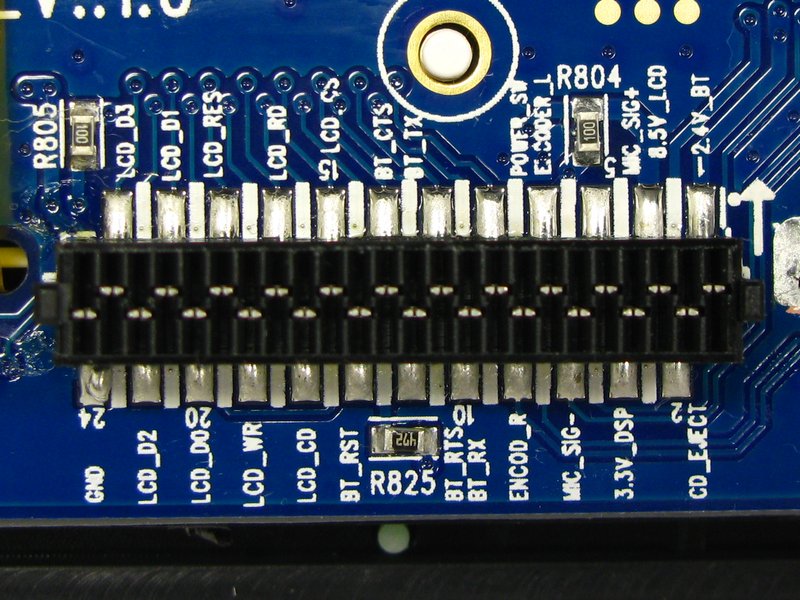
Here is a clearer shot of the faceplate's right side connector (right, when looking at the LCD display from the front).
The faceplate's left side connector.
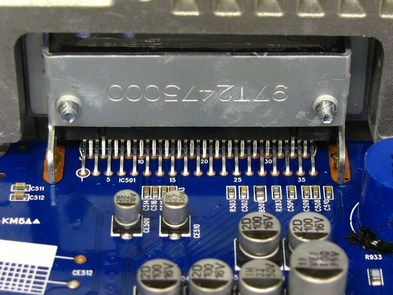
A clearer shot of the big amplifier IC's pins.
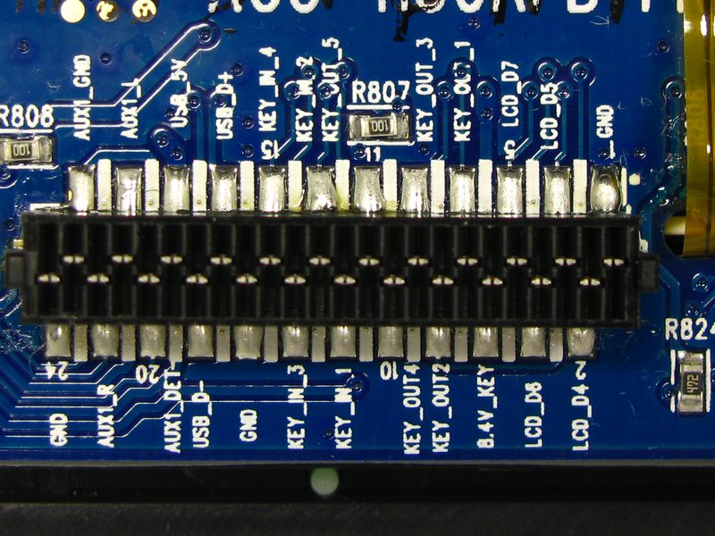
Clearer shot of the big connector block's pins on the motherboard.
A front view of the amp IC. See those 4 small beige capacitors in the middle-left of the shot (partially hiding behind the big silver caps, starting with C514)? The audio signals from the DSP (that I detailed earlier in this post) run to these, through them, and then into the amp IC.
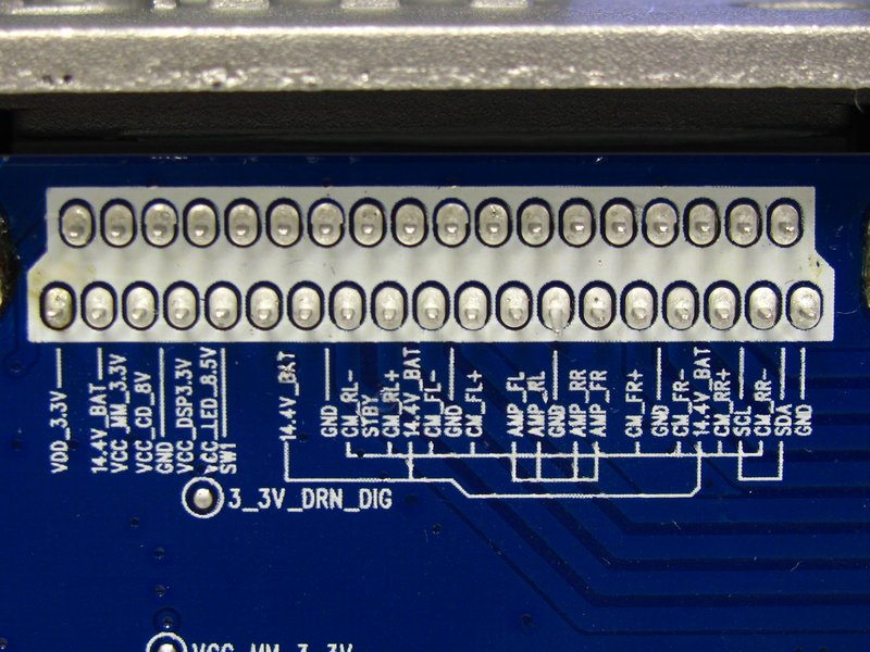
Here is the back side of the board to which the large rear connector block is connected. Here are the labels for the top "accessory" connections and the middle speaker outputs.
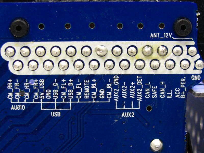
The bottom rows were a little harder to photograph since the big cap and filter choke were blocking them. Here's the left side of the bottom row.
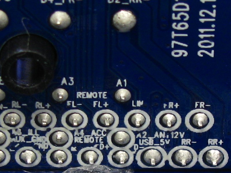
And the right side.
Maximum OCD nerdiness, I know. It is as much for your benefit as it is mine since it's actually easier for me to refer to these images sometimes since I don't always have my laptop on me with the originals. Anyway, it's an excuse to take super-macro pictures, and everyone loves those right? Right?? *crickets* Right?????Last edited by bmwman91; 11-05-2014, 07:14 PM.Leave a comment:
-
I saw those too and got hopeful at first. However, when I probe those I get nothing useful. The REMOTE line puts out ~4V regardless of whether the unit is turned on or not (as long as there is constant 12V). The ANT-12V line has no voltage on it at all at any point, which is also weird.Leave a comment:
-
Just noticed, in this picture:
It says "REMOTE". That is likely your amp turn on. It also says "ANT_12V" at the top right. That is likely antenna turn on.Leave a comment:
-
The remote out is in the pre-amp plug (http://www.ebay.com/itm/Blaupunkt-4-...-/221135740785) or what has always been DIN spec for preamp anyway, who knows what these freaks did...anyway, one of those pics goes to 5V when the deck is on, I used a reed switch to turn on the amps.Leave a comment:
-
Verrrrrrry interesting.... Faceplate seems like it would be easy to tackle the exterior parts w/ some Plastidip.
Fortunately the beeping does not occur with every single button press - mainly when you drop the volume to 'MIN' is when it beeps.
Good luck sir - will be interested to see what happens!Leave a comment:
-
Good to know.
In this case, it looks like the unit was designed for a fixed antenna and no amp, hence the lack of dedicated output for that stuff. The 8.5V LCD power rail switches on and off with the unit, which might even be enough to serve ant/amp switching functionality, although it is still a better idea to use a relay to protect the unit.Leave a comment:
-
As far as the switched antenna/amp signal, make sure you are in "Radio" as some stereos will lower the antenna if you are in CD or AUX. It might not have one at all though if the car it came form had a fixed antenna and no amp, or the amp was switched on with the ignition.Leave a comment:
-
Thanks man. There's nothing like taking stuff apart for fun! Although using a 10lb sledge can be even more fun for "disassembly".....
Quick updates, good news and bad news.
The bad news:
- There probably is no way to get rid of the system BEEP sound since the DSP chip directly mixes it into the digital audio stream before getting to the 4 pre-amp outputs from the chip. So...the BEEP most likely has to be lived with.
- No pre-amp outputs on the rear ISO connector. The ISO standard for this says that some of the pins at the top of the connector are for pre-amp outputs, but they are instead used for USB input.
The good news:
- Making pre-amp outputs suitable for RCA connections should be pretty simple. The onboard "pre-amp" signal going from the DSP chip to the amp IC are ~2.5V. I would definitely not tap into that directly since any fault that might happen could potentially blow out the DSP chip's outputs, so an opamp buffer circuit is advisable. Heck, that would allow for a 5V pre-amp signal which might be preferable anyway.
- As far as I can tell, there are connections for USB and a second analog AUX input on the main rear connector. Bummer that there are no pre-amp outputs there (the pins that the ISO standard assign for that are used by the USB connection instead), but it does make for the option to have USB and AUX inputs that don't clutter up the dash.
Other observations:
- The big amp IC burns up a shit ton of power. That big aluminum heat sink on the back gets warm/hot to the touch even with nothing hooked up to the speaker outputs and no audio input. Certainly for my unit, when I make pre-amp outputs, I am going to remove that sucker.
- The faceplate buttons are not as responsive as I would like. The CD43 just "feels" a lot more responsive. This RMT200 will sometimes do nothing when I push a button and I have to try a second time which is annoying, but not that big of a deal.
OPEN QUESTIONS:
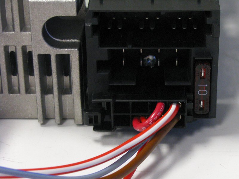
- Just to make sure that I have this right, is this the correct assignment of 12V power wires?
--- Large red/white = constant 12V
--- Smaller red = switched 12V
--- Position 5 on bottom plug = SAFE security connected to switched 12V
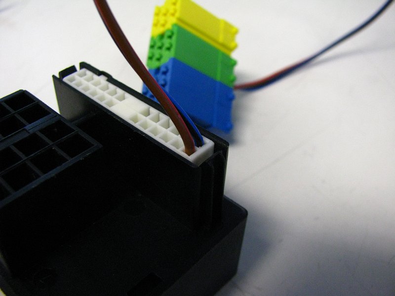
Here's how I have dealt with the SAFE connection for now. Thoughts?
- Let me know if I have this right as far as amp/antenna on/off voltage.
--- For the 12V antenna / amp signal, there is actually no switched output for this at all (at any voltage). I probed around and turned the unit on/off and none of the aux and did not find any pins that had switched on/off output.
--- As of now, the only option is to use the switched 12V from the ignition for an antenna/amp on/off signal.
As a side note on this, if I was to make a pre-amp board, I think that it would be easy enough to also add a connection for switched 12V for the amp/antenna. The 8.5V power rail for the faceplate LCD switches on and off with the unit, so that could probably be used to drive a solid state relay or something to make a switched 12V output for the antenna/amp.Last edited by bmwman91; 11-05-2014, 05:26 PM.Leave a comment:


Leave a comment: