
Dealing with premium amp bypass
Pretty sure this is what Barry was getting at earlier in the thread:
As I explained, the current board doesn't add pre-outs, so it doesn't matter whether/not you have the premium amp. It does matter if you've bypassed the premium amp though, since the OEM radio/head unit only supports speaker level outputs.
If you don't have an aftermarket amp you need to connect your OEM radio speaker outs to your speakers and you're limited to 5W per channel. If you do have an aftermarket amp, you need to use its speaker level inputs or not use it all with this version of Jay's board.
-
I really love seeing projects like this, its sad that I longer have enough time on the side for fun things like this. good for you! also check you PM I'll be sending you a message.Leave a comment:
-
-
They're not, and I never implied otherwise. They're cleaner than a buck regulator would be. Was pointing out his 3.3V supply is clean, and not to look there for noise issues.Last edited by earthwormjim; 04-18-2017, 11:30 AM.Leave a comment:
-
Yep. I was asking why a LDO would be more quite then a non-low-drop-out linear regulator - both should be running an op-amp internally. And both sinking excess current as heat. Even so, unless you have some unstable feedback internally, both should be about the same.Last edited by george graves; 04-18-2017, 02:36 AM.Leave a comment:
-
Cool, so looks like you found what was picking up the RF emissions; the EQ circuitry and/or the audio cables.
Hopefully you can solve it by relocating the module as you were saying. If relocating or more filled out ground planes doesn't help, you could use a transistor PCB heatsink to act as a verticle shield, similar to what you have now.
They're pretty cheap.
Something like this:
Any point of the antenna that has a ground underneath it, is no longer an antenna, so you effectively reduce the antenna length to some odd value that deviates from 1/4 or 1/8 of a wavelength, similar to what your wire does. But definitely scratch that suggestion, shielding is way way better to do, and you found what to shield.All the datasheets I read say to keep copper out of that area right underneath the antenna. They're still effective like that? Then again, it still streamed music with a wire soldered on the antenna... I suppose it's just a trade-off of range vs. EMI in some cases like this?Leave a comment:
-
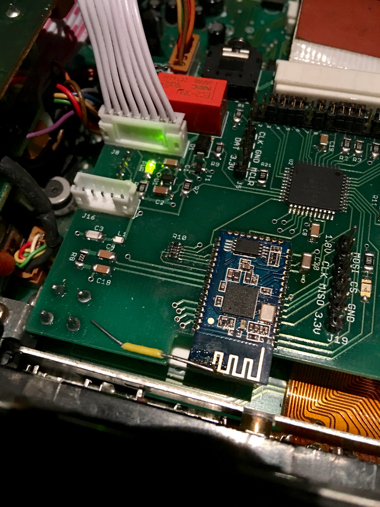
Gave that a shot today. I didn't have copper tape (ordered some) so I took a shield off some junk I had and soldered on a lead so I could ground it and hold it in various positions. Covering the non-antenna part of the BT module didn't change anything unfortunately, nor did covering just my analog section (as expected, since the noise is there without the audio cable even being plugged in). The positioning below kills it though:
The most crucial area to make the noise go away seems to be the most forward section of that shield, where there is currently no PCB or ground planes, which seems kinda relieving since there are known improvements I can make there. This also kinda makes sense because the unbalanced audio out cable is right behind the shield, and some other audio mixing/EQ circuitry is on the vertical board that it reaches over.
All the datasheets I read say to keep copper out of that area right underneath the antenna. They're still effective like that? Then again, it still streamed music with a wire soldered on the antenna... I suppose it's just a trade-off of range vs. EMI in some cases like this?
Still thinking I should extend the PCB frontwards as far as possible and use stitched ground pours on both sides, then shift the BT chip as far away as possible. Hopefully it doesn't require some kind of vertical shield soldered on the board... I've got the copper tape coming tomorrow so I can at least try building up an extended ground plane with that.Leave a comment:
-
Jay how close are you to being able to add pre-outs? A lot of premium sound cars have bad amps, and I bet many folks have bypassed the premium amp by now. I have my car harness setup to support both pre-out and the inline premium amp so I'm ok without pre-out support for now. But I would definitely prefer a pre-out arrangement as I'm sure most folks would.
Not something needed for a minimal viable product version of your board, but should be high on the dev list.Leave a comment:
-
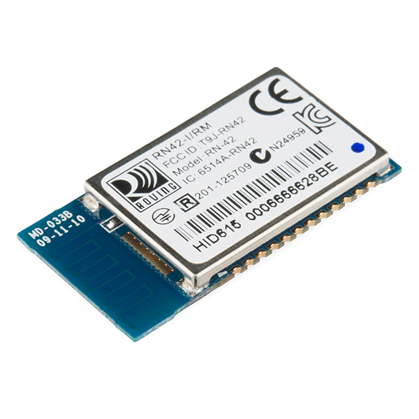
Jay, I'd test out first if I'm right about having to move the jumper, I'm just basing it off your pictures. See if there is continuity between that pin and the antenna already. Where did you get that module anyway? If ordering from Alibaba, you should be able to specify from the vendor, or they may have an external antenna version.
Most that are FCC certified, do have a shield over the module.Originally posted by jaysterling
Sounds like it is time to bust out the copper tape, and see where you might need ground planes or shields.
On my bluetooth project, my mating board had all available space filled in with ground pours.
You could also extend your PCB underneath the module's antenna, and pour in a ground plane. Covering underneath part of the PCB antenna with ground, should weaken RF signals like your added wire does too. You can test with strips of grounded copper tape.
It could very well help, if you can move the module and wire it up with thin leads, test it out. On the power supplies I designed, I ended up putting stuff on flexible magnetic wire, and moving it around while powered up, to see if my EMI emissions changed in real time.Originally posted by jaysterlingLast edited by earthwormjim; 04-16-2017, 06:30 PM.Leave a comment:
-
Oh ok, makes sense about killing the impedance matching, so it's just the reduced signal strength that's making the noise go away.
The problem with the external antenna solution is the pick-n-place machines that will be doing the assembly can't desolder components right? So I'd need to try to source some modules that already had the right jumpers soldered on, which I'm not sure is possible. I can't imagine manual rework of each module is cheap. If f I did go that route, I'm also clueless what I'd actually do with the antenna design to fix the problem.
So you don't think moving the chip as far that corner as possible, adding a top ground plane + extend the bottom ground plane up around the chip would do anything? I gotta think this can be solved without an external antenna since any run of the mill BT receiver uses a similar module + chip antenna and they don't have this problem, even without a shield over the module. When you look at one though (I tore apart a cheapo one I had) it'd definitely a 2 layer ground plane with lots of stitching that fills everywhere except right under the antenna, all things I'm not currently doing.Leave a comment:
-
That module should have provisions for an antenna pin. Looks like if you desolder the 0402 jumper leading to the antenna, and move it over to the left position, that lets you wire an antenna to pin 43.
I'm guessing what you did, is you messed up the impedance matching of the antenna, so you ended up weakening the RF signals. It's no longer a nice fraction of a wavelength.
Normally those little modules (FCC certified ones) have a shield covering everything except the antenna, wonder if that might help?Last edited by earthwormjim; 04-15-2017, 10:51 PM.Leave a comment:
-
Thanks for the suggestions guys, I gave them all a shot today. I tried all kinds of caps everywhere, up to like 260 uF ones, none made any noticeable difference in my case. I was trying all kinds of stuff swapping what was grounded where and trying to further separate the power supplies, thinking the noise was coming from digital switching currents. None of that changed anything either. BTW, this noise that's left is 2 successive ticks happening at 40 Hz. All the high-frequency buzzy stuff was fixed with power supply/ground separation earlier.
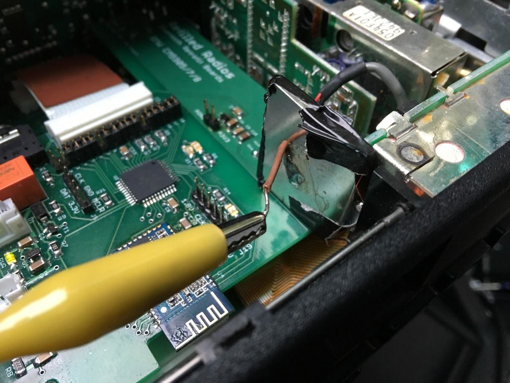
I then had a few discoveries that led me to the problem. First, and I can't believe I hadn't tested this, but I unplugged just the audio out cable from the board, cranked the volume, and the noise was still there! So it's not coming from my audio circuit, it's getting into the final output simply if the BT chip is on and connected. Then I started grabbing around the board with my hands and noticed changes and decreases in the noise. Eventually, I put my finger right on the BT chip antenna and bingo - gone! And after spending a ton of hours today trying to track this thing down, this little yellow wire fixes it:
Yes, that's a piece of wire maybe an inch long soldered to the chip antenna that goes nowhere. Total black magic... But seriously, my best guess at what's going on is the noise is due to RF interference from the antenna, and the tiny piece of wire is enough to move the signal traffic a little farther away from the audio circuitry? My finger was sort of doing the same, or at least just making RF unable to reach the antenna (since I'm a poor conductor)? Let me know if I'm way off.
So at least I kinda know the general area of the problem now and a way to fix it. Problem is how to fix it the non-hacked way. I can definitely move the BT chip over farther to that side of the board where the yellow wire runs to, and I can use the ground planes more aggressively around the antenna to try to contain the RF traffic to that little area, but it just seems tough to really be sure it's fixed before spinning another board and trying it.Leave a comment:
-


Leave a comment: