LC-1 AFR reading problems.

Collapse
X
 
  • Time
  • Show
Clear All
new posts

  • ak-
    replied
    UPDATE: Fixed.

    Embarrassed to say that all I needed was a new sensor and my old new one (yes, brand new) was just fouled some how.


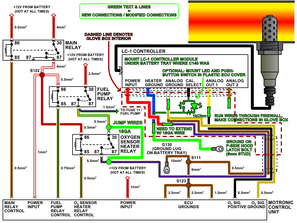
    So for anyone who is wondering how to connect these to use with megasquirt to only have 1 o2, my wiring was correct from the get-go.

    [LC-1 wire]

    1. RED - - - - - - - - -12v switched - - - - - - - - - - Defroster switch (or any other convenient 12v switched)
    2. BLUE - - - - - - - - Heater ground - - - - - - - - - ECU shock tower ground
    3. WHITE - - - - - - - System ground - - - - - - - - -ECU shock tower ground
    4. BLACK - - - - - - - Calibration wire - - - - - - - - -ECU shock tower ground
    5. YELLOW - - - - - - Analog 1 (narrowband) - - - - Capped off
    6. BROWN - - - - - - -Anolog 2 (wideband) - - - - - Signal wire on the stock o2 wiring (black wire of the 4) AND AFR gauge signal wire (white)

    Leave a comment:


  • ak-
    replied
    Sorry for my late reply. I'm pretty urged to get this fixed.


    Originally posted by liquidgroove
    According to BMWman91's diagram

    Looks like the white wire is analog ground. He had it connected to stock O2 ground on O2 sensor connector.

    Not sure if it will fix your problem, but worth a try.

    [IMGhttp://bmw.e30tuner.com/images/articles/lc1install/bmw002.png[/IMG]
    I have read and re-read this along with many other write-ups!
    I have the white analog ground grounded at the ECU ground/shock tower. I hope you weren't mistaking the white wire that comes out of the AFR gauge as an analog ground? The factory grounds in my o2 harness didn't work well for me (and many other people), hence why I grounded everything at the shock tower/ECU ground.

    Originally posted by george graves
    Good post ak. Just to add, you might have to hit "program" on each screen before moving to the next. If you want to double check it...disconnect, relaunch it, re-connect, and then see if the changes stuck.
    I did just that and nothing. ):

    I need to make the time to phone-in Innovative. I might buy another o2 wideband replacement sensor from Autozone to test if they have a returnable return policy.
    I'll update as I go.

    Leave a comment:


  • george graves
    replied
    Originally posted by ak-
    It would read good on TS, but not the gauge back when I introduced the problem to you.
    It used to read wonky on TS, but that went away after I grounded everything to the same ground (ECU shock tower).

    On the LC1 programmer, I set the Analog 1 tab to:
    0v = 7.35 AFR
    5v = 22.39 AFR

    Analog 2:
    0v = 7.35 AFR
    5v = 22.39 AFR

    Then hit [Program].
    Good post ak. Just to add, you might have to hit "program" on each screen before moving to the next. If you want to double check it...disconnect, relaunch it, re-connect, and then see if the changes stuck.

    Leave a comment:


  • liquidgroove
    replied
    Originally posted by ak-
    The wideband controller itself is in my glovebox and my coil is mounted right behind my passenger headlight!

    [LC-1 wire]

    1. RED - - - - - - - - -12v switched - - - - - - - - - - Defroster switch
    2. BLUE - - - - - - - - Heater ground - - - - - - - - - ECU shock tower ground
    3. WHITE - - - - - - - System ground - - - - - - - - -ECU shock tower ground
    4. BLACK - - - - - - - Calibration wire - - - - - - - - -ECU shock tower ground
    5. YELLOW - - - - - - Analog 1 (narrowband) - - - - Capped off
    6. BROWN - - - - - - -Anolog 2 (wideband) - - - - - Signal wire on o2 (black wire of the 4) AND AFR gauge signal wire (white)
    According to BMWman91's diagram

    Looks like the white wire is analog ground. He had it connected to stock O2 ground on O2 sensor connector.

    Not sure if it will fix your problem, but worth a try.

    Leave a comment:


  • jntar
    replied
    I guess at this point give innovate a call. They helped me diagnose my lc-1 issue.

    Leave a comment:


  • ak-
    replied
    Originally posted by whodwho
    I would have to go back and look but I thought I remembered that it would read good on the gauge and not in TS?

    And does TS show the same now?

    I would get it working right with MS disconnected, it sounds like it is behaving like you have it set for NB when it goes from one extreme to the other
    It would read good on TS, but not the gauge back when I introduced the problem to you.
    It used to read wonky on TS, but that went away after I grounded everything to the same ground (ECU shock tower).

    On the LC1 programmer, I set the Analog 1 tab to:
    0v = 7.35 AFR
    5v = 22.39 AFR

    Analog 2:
    0v = 7.35 AFR
    5v = 22.39 AFR

    Then hit [Program].

    I exited the programmer and reopened it to make sure it was saved and such.

    I've connected my Narrowband to the gauge before and it pegs at 7.4 rather than 22.2 AFR.

    Leave a comment:


  • whodwho
    replied
    I would have to go back and look but I thought I remembered that it would read good on the gauge and not in TS?

    And does TS show the same now?

    I would get it working right with MS disconnected, it sounds like it is behaving like you have it set for NB when it goes from one extreme to the other

    Leave a comment:


  • ak-
    replied
    Originally posted by jaywood
    Good luck :p keep us updated if you figure it out.
    :puppy:


    So I made both outputs for wideband.
    Brown went to the gauge, and Yellow to signal o2/MS (not that the wire to MS matters because I should still get an AFR reading on my gauge regardless, right?)


    And...... nothing. Same thing. Pegged to 22.2 AFR on idle.
    If I blip throttle it hits 7.4, then back to 22.2 AFR.

    Leave a comment:


  • whodwho
    replied
    Originally posted by ak-
    Can you explain what do you mean by including the switch vs. straight ground? I have the LED and calibration setup correctly where it flashes warm-up mode and allows me to calibrate.
    Sounds like you have it hooked up correctly then

    "4. BLACK - - - - - - - Calibration wire - - - - - - - - -ECU shock tower ground"

    Made it sound like you had the black wire connected to ground without the switch

    carry on... 8^)

    Leave a comment:


  • jaywood
    replied
    Good luck :p keep us updated if you figure it out.

    Leave a comment:


  • ak-
    replied
    Originally posted by jntar
    Innovate makes many gauges. Each of which has different input wire colors.

    Yes, set both as if they were wideband signals so both the gauge and the megasquirt sees 0-5v. Be sure you go calibrate the MS unit in tunerstudio to innovate lc-1 0-5v.

    Does it read the same in tunerstudio as it does on the gauge?
    Originally posted by whodwho
    4. BLACK - - - - - - - Calibration wire - - - - - - - - -ECU shock tower ground

    This one should not be connected except while calibrating

    6. BROWN - - - - - - -Anolog 2 (wideband) - - - - - Signal wire on o2 (black wire of the 4) AND AFR gauge signal wire (white)

    You don't want to share the output, set both outputs for 0-5v output and use one for each
    I'll set both to wideband outputs and use them separately as advised and see what happens.

    Originally posted by jntar
    This is what I was thinking, but the lc-1 diagrams say to have it grounded unless running a specific gauge. Maybe I read them wrong. I have the calibration button and led hard wired in.
    Originally posted by nando
    aren't you only supposed to ground the calibration wire when you're calibrating it? or is that through the switch?

    I'd pull that off and see what happens. did you already go through the calibration steps?
    This is the gauge I'm running - what came with the 6wire kit.


    Originally posted by whodwho
    It grounds thru the switch to initiate the calibration mode and the feeds the led the results codes
    Originally posted by nando
    Yeah, im wondering if he included the switch or wired straight to ground
    Can you explain what do you mean by including the switch vs. straight ground? I have the LED and calibration setup correctly where it flashes warm-up mode and allows me to calibrate.


    I'm about to try and set both outputs to wideband and make them exclusive to the gauge and MS to see what happens - I'll update in a bit.

    Leave a comment:


  • nando
    replied
    Yeah, im wondering if he included the switch or wired straight to ground

    Leave a comment:


  • whodwho
    replied
    It grounds thru the switch to initiate the calibration mode and the feeds the led the results codes

    Leave a comment:


  • nando
    replied
    aren't you only supposed to ground the calibration wire when you're calibrating it? or is that through the switch?

    I'd pull that off and see what happens. did you already go through the calibration steps?

    Leave a comment:


  • jntar
    replied
    Originally posted by whodwho
    4. BLACK - - - - - - - Calibration wire - - - - - - - - -ECU shock tower ground

    This one should not be connected except while calibrating

    6. BROWN - - - - - - -Anolog 2 (wideband) - - - - - Signal wire on o2 (black wire of the 4) AND AFR gauge signal wire (white)

    You don't want to share the output, set both outputs for 0-5v output and use one for each
    This is what I was thinking, but the lc-1 diagrams say to have it grounded unless running a specific gauge. Maybe I read them wrong. I have the calibration button and led hard wired in.

    Leave a comment:

Working...