
Hey guys, I've been thinking about this for a while and just sat down to look at the wiring diagrams and ETM on the m42 318is and the regular motronic 1.3 m20b25.
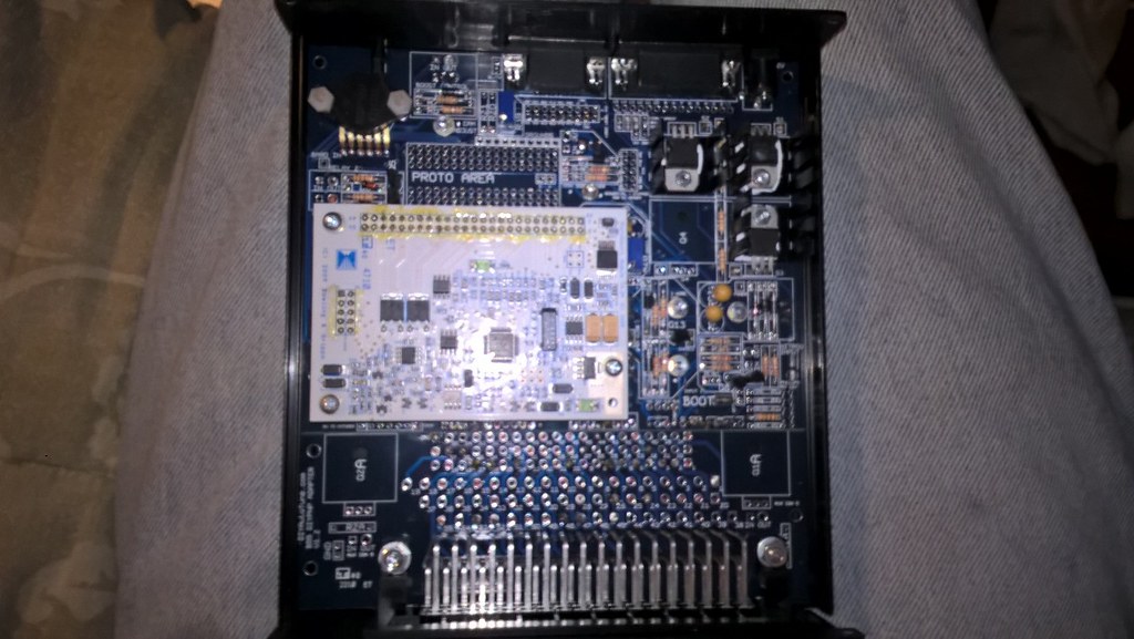
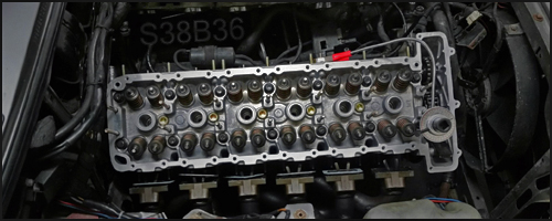
I was able to source a male 88 pin connector and I have an extra 55 pin diypnp microsquirt based ms2 for an e30. I am wanting to convert my m42 to standalone and do it in a totally reversible manner. Since there is no plug and play 88 pin megasquirt 2 unit available for the m42, my plan was to make a wiring adapter that would plug in to the engine harness and allow the 55 pin ecu to power it just the same. So far I have a lot of it figured out but am looking for feedback and hopefully answers to some questions. I found the m42 pinouts listed and compared them to nando's 55 pin to megasquirt table and made my own chart to cross reference the two. Here is an under the hood look at the ms unit I have.
The first m42 e30 pinout is based on this link
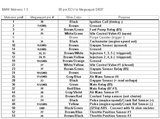
Then the 55 pin is based on this image
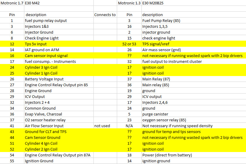
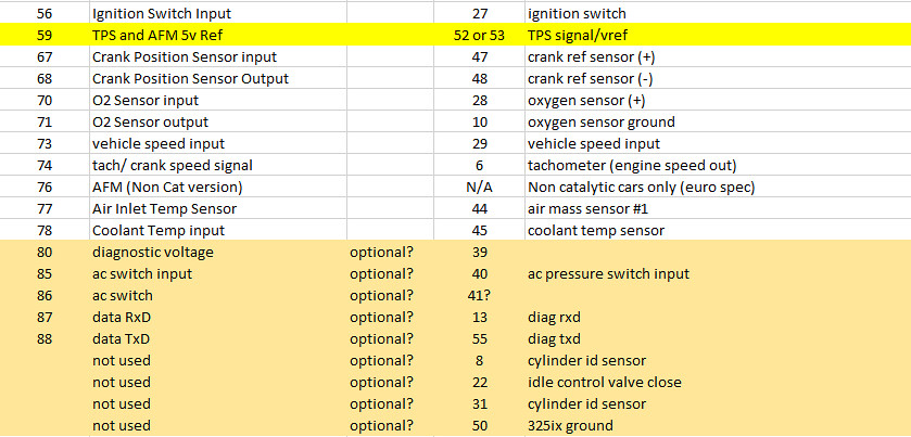
I compared the two and tried my best to match them based on a couple other diagrams I found and ETM's. This is what I came up with.
A couple of questions that I have.
1. How do I power the coils? Looking at the ETM these are run individually, as sequential ignition. I have 3 drivers. Can I just set up for wasted spark using 2 drivers as is?
2. In order to run wasted spark, do I need to utilize/ add in a provision for the cam sensor? Will I need to run Dual Wheel with missing tooth? Or can I use the Cylinder ID sensor with the connection from the cam sensor on the m42?
3. Do I need to tie all of my grounds together? Or can I just pick a ground and match it up with another ground?
4. The m42 uses a 2 wire ICV while the M20 uses a 3 wire. I am left with only one input for the ICV currently on the m42 harness. Can I set it up similar to the 3 wire and just set the % open value in tunerstudio to get it to modulate between that and 0 when it goes into idle mode? Essentially i would calibrate the ICV as an open only type unit and would find where that open point is, if that makes any sense. I missed it above but pin 29 needs to go to pin 4 (or pin 22 depending) on the m1.3 harness.
5. I know the wires of the TPS need to be changed from WOT switch style TPS to the variable that the m42 runs. But when I look at the ETM, the m20 engine doesn't show which wire is the ground. Does pin 12 go to 52 or 53? Same with pin 59. Is the tps ground shared with the afm ground or similar?
6. Does the diagnostic port need to be connected? I am not sure those do anything, Is that to the port under the hood for resetting the oil light etc?
7. Does anything else look backward or like this wouldn't work? I think the coils firing correctly and the icv are the hardest part of making this work.
8. Do any of these wires need to be shielded? How do I go about doing that?
Thank in advance guys
I was able to source a male 88 pin connector and I have an extra 55 pin diypnp microsquirt based ms2 for an e30. I am wanting to convert my m42 to standalone and do it in a totally reversible manner. Since there is no plug and play 88 pin megasquirt 2 unit available for the m42, my plan was to make a wiring adapter that would plug in to the engine harness and allow the 55 pin ecu to power it just the same. So far I have a lot of it figured out but am looking for feedback and hopefully answers to some questions. I found the m42 pinouts listed and compared them to nando's 55 pin to megasquirt table and made my own chart to cross reference the two. Here is an under the hood look at the ms unit I have.
The first m42 e30 pinout is based on this link
Then the 55 pin is based on this image
I compared the two and tried my best to match them based on a couple other diagrams I found and ETM's. This is what I came up with.
A couple of questions that I have.
1. How do I power the coils? Looking at the ETM these are run individually, as sequential ignition. I have 3 drivers. Can I just set up for wasted spark using 2 drivers as is?
2. In order to run wasted spark, do I need to utilize/ add in a provision for the cam sensor? Will I need to run Dual Wheel with missing tooth? Or can I use the Cylinder ID sensor with the connection from the cam sensor on the m42?
3. Do I need to tie all of my grounds together? Or can I just pick a ground and match it up with another ground?
4. The m42 uses a 2 wire ICV while the M20 uses a 3 wire. I am left with only one input for the ICV currently on the m42 harness. Can I set it up similar to the 3 wire and just set the % open value in tunerstudio to get it to modulate between that and 0 when it goes into idle mode? Essentially i would calibrate the ICV as an open only type unit and would find where that open point is, if that makes any sense. I missed it above but pin 29 needs to go to pin 4 (or pin 22 depending) on the m1.3 harness.
5. I know the wires of the TPS need to be changed from WOT switch style TPS to the variable that the m42 runs. But when I look at the ETM, the m20 engine doesn't show which wire is the ground. Does pin 12 go to 52 or 53? Same with pin 59. Is the tps ground shared with the afm ground or similar?
6. Does the diagnostic port need to be connected? I am not sure those do anything, Is that to the port under the hood for resetting the oil light etc?
7. Does anything else look backward or like this wouldn't work? I think the coils firing correctly and the icv are the hardest part of making this work.
8. Do any of these wires need to be shielded? How do I go about doing that?

Thank in advance guys
Comment