-
Excellent work! Awesome models too and I think it is great you are doing the machine work yourself. I'm jealous -
Unfortunately there hasn't been much happening with the build in the past couple weeks. I've been working out a couple issues with my other car so that I can drive that one while I do the swap. The past few days I've been looking into exhaust since I'm going to want a custom set-up to go with my RD headers. Right now I'm thinking I'd like to try and mock up the exhaust, tac it together, then get a friend to weld it up nice. So last night I took some measurements off the car and came up with a rough model of the stock exhaust (leaving out the x-pipe cat and resonator)...
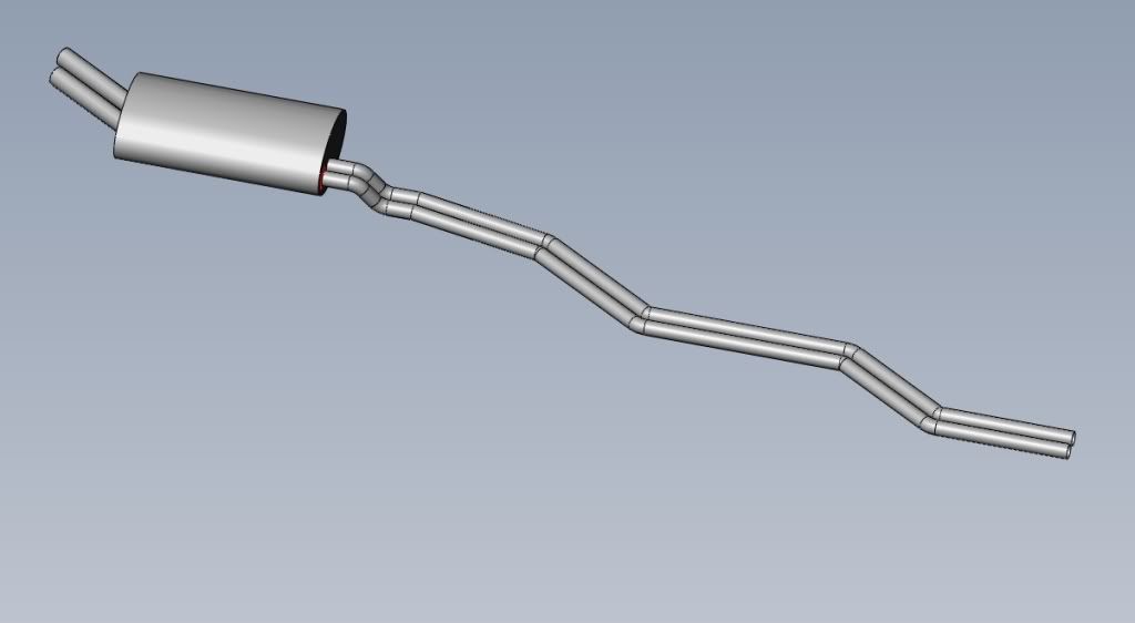
After doing some reading I've decided to go with a single 2.5" exhaust because it's light weight, simple, and because going any diameter larger than 2.5" would require a custom made merge collector. For the power the motor should be making 2.5" will be sufficient.
I drew up an exhaust using only 45" bends because those are readily available from any place that sells misc. exhaust tubing.
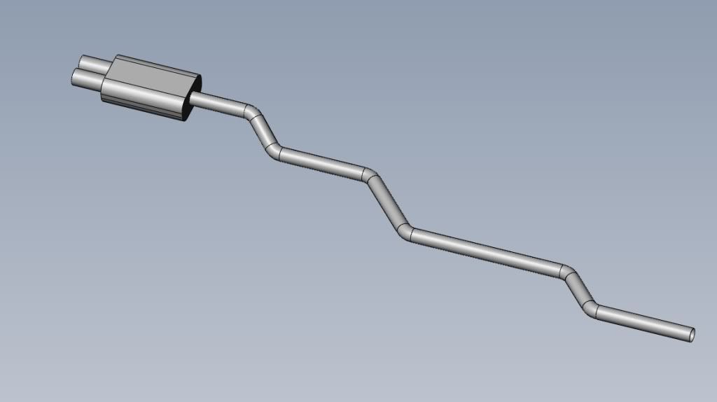
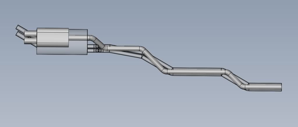
I'm probably going to end up buying components from Vibrant since they are local and I've heard good things about their stuff. In the place of the stock mid section I'm going to put a 13" catalytic converter and a 12" resonator, and the muffler I'm thinking is a streetpower flat black 2.5" in dual 3" out (dimensions in the model reflect the dimensions of the muffler). It looks like I should be able to offset it just enough to have the dual tips centred in the valance cut out. If not then I'll just skew it on a slight angle to centre the tips. This is how the two look overlaid...
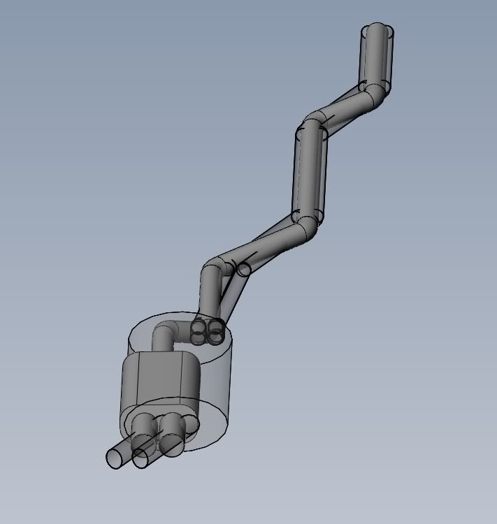
I'm also planning on having the mid section connected by v-band clamps so it will be simple to remove it and install a test pipe for the track if I want to down the road.
I'm currently looking into pricing of the components and parts.
Cheers.Leave a comment:
-
-
A quick update.
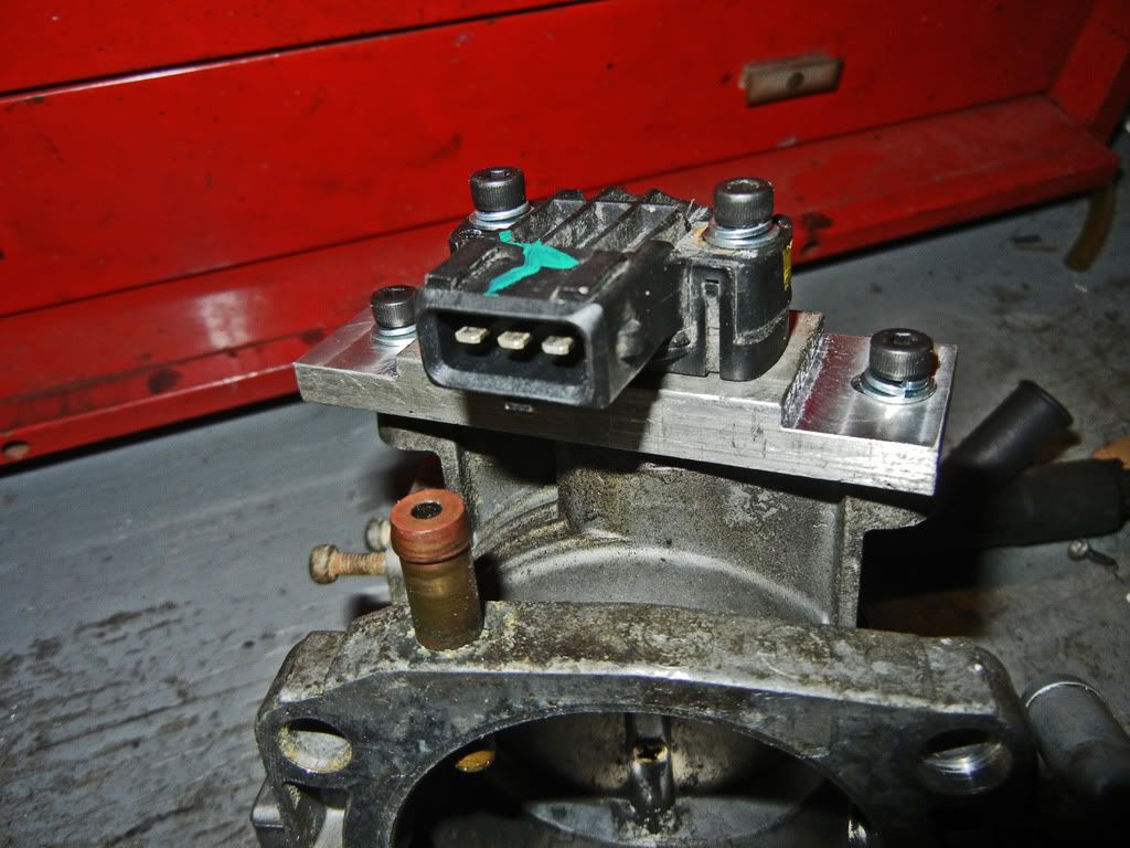
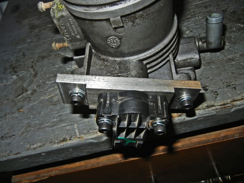
Yesterday I machined a simple adapter plate so that I can mount a variable TPS from an M52 to my M20 throttle body
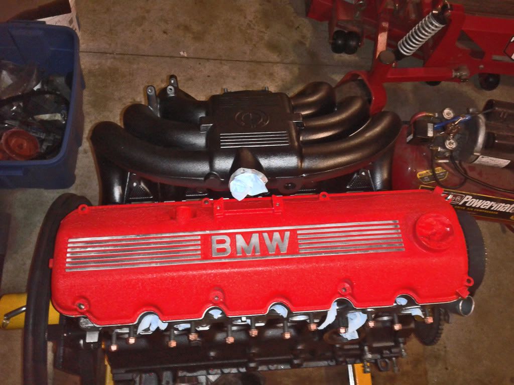
I also cleaned up my intake manifold yesterday, and today I gave it a satin black rattle can paint job. I like how it turned out...
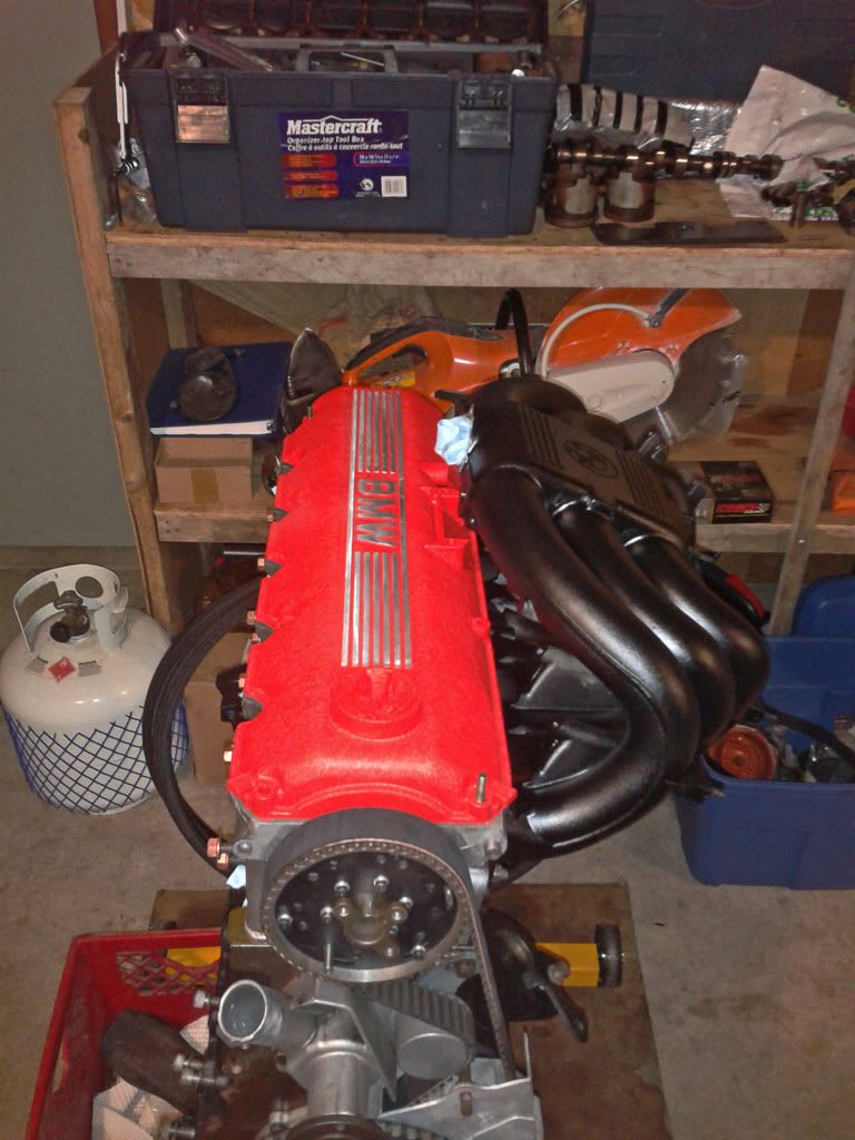
Now all I need is some shiny headers... which apparently I won't be getting until early July...
Leave a comment:
-
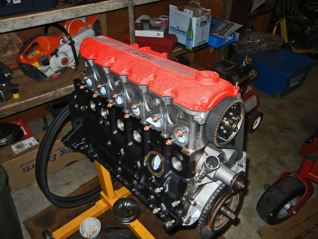
Quick update: Motor is mostly assembled.
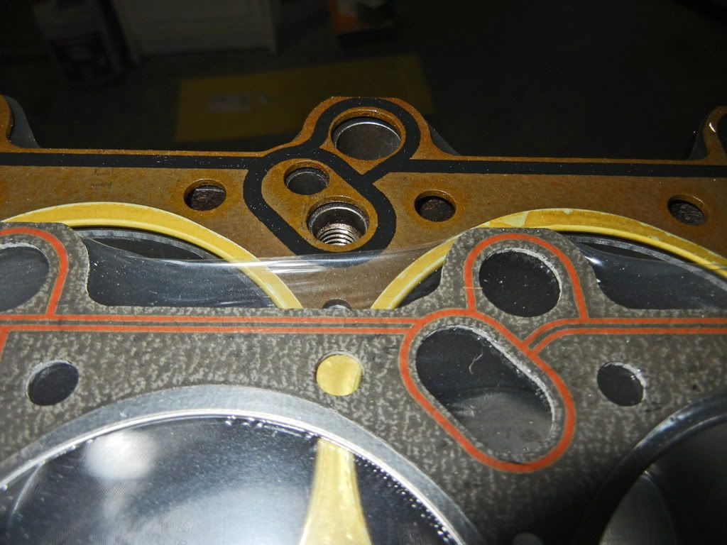
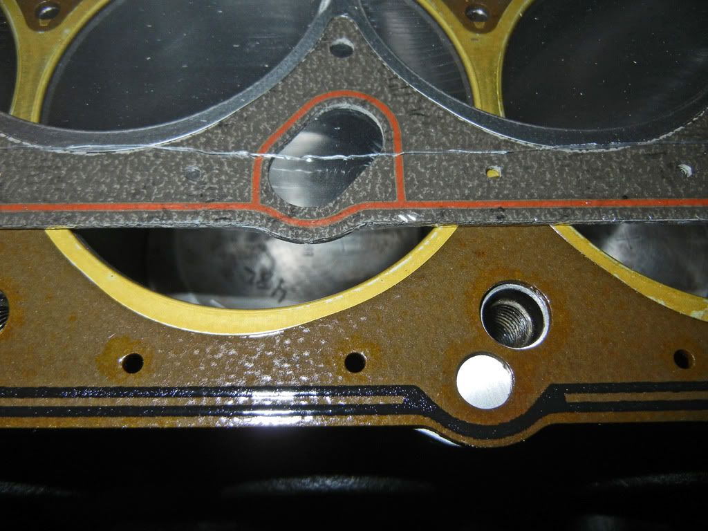
I spent a couple hours this evening and assembled most of the motor. After getting the water pump and tensioner installed I went to install the head. Now I know this one has been beaten to death already, but just to show everyone the difference between the Victor Reinz and Goetze head gaskets:
The gasket on the motor is the Goetze and the one still in the plastic is the Victor Reinz. You can see that the sealing strip on the Goetze is much beefier than on the Victor Reinz
After torquing the head on I installed the exhaust manifold studs and popped the valve cover on. Things are coming together....
I also got news today that the RD headers I ordered are finally ready. They are only 7 weeks late... but better late then never right :).
That's all for now.
Cheers.Leave a comment:
-
Progress update: Things are back on track...
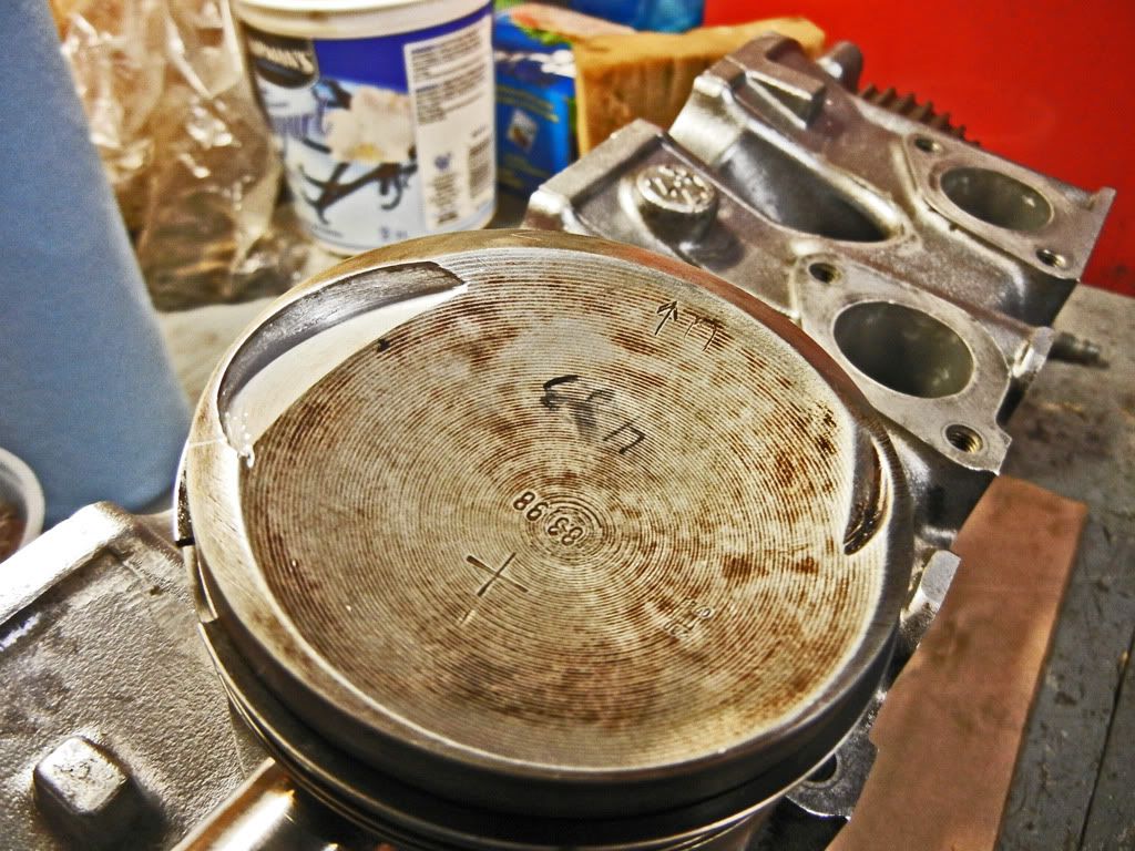
So as I mentioned, I checked my valve to piston clearance (the proper way) and found that my clearance on the intake valve was this much...
Since that was not enough I took the bottom end apart so that I could machine the intake valve relief deeper on each piston. After scrounging around at work I found this nice dividing head with tilt adjustment tucked away in a crate of random tooling that was bought at an auction and never used. After cleaning it and lubing it I set it up on the mill...
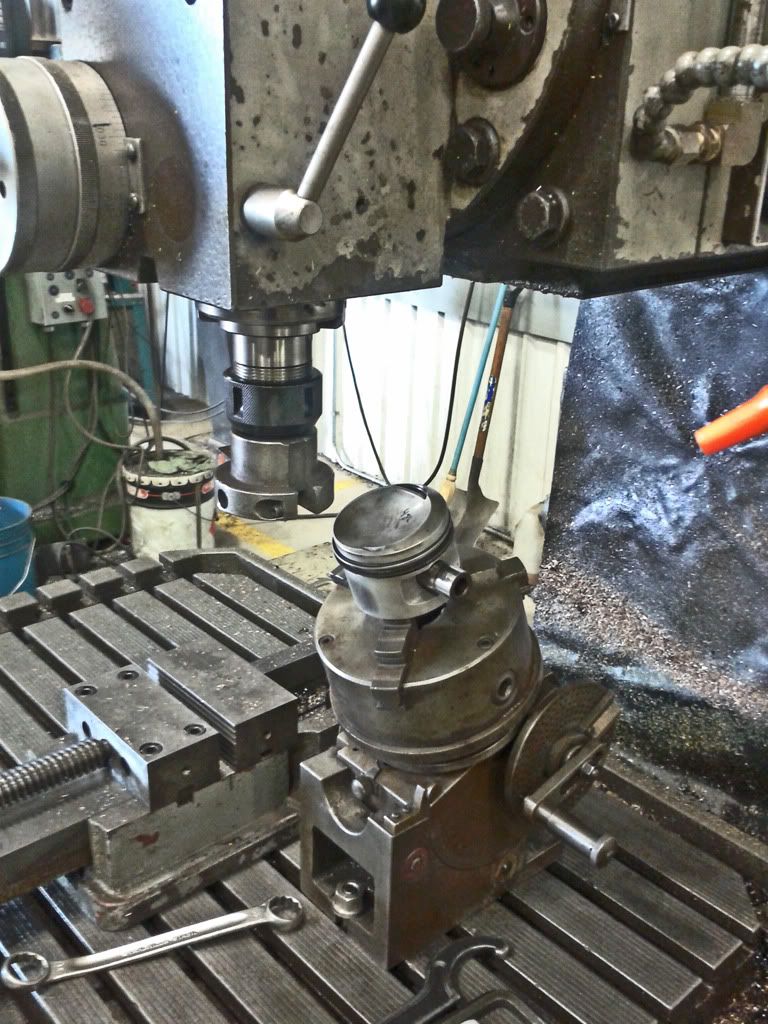
The tool I used to cut the valve relief was pretty ghetto as well. As you can see it was a simple boring head meant for fairly large diameters. Instead I just stuck the sharpened bar of HSS on an angle in the middle at approximately the proper radius and locked it down with the set screws in the tool. To set the angle and find the center of the pocket I just lined everything up as closely as I could by eye. I would mark each pocket with marker and take a light cut to check the set-up and make small tweaks as necessary. Here's a before and after picture...
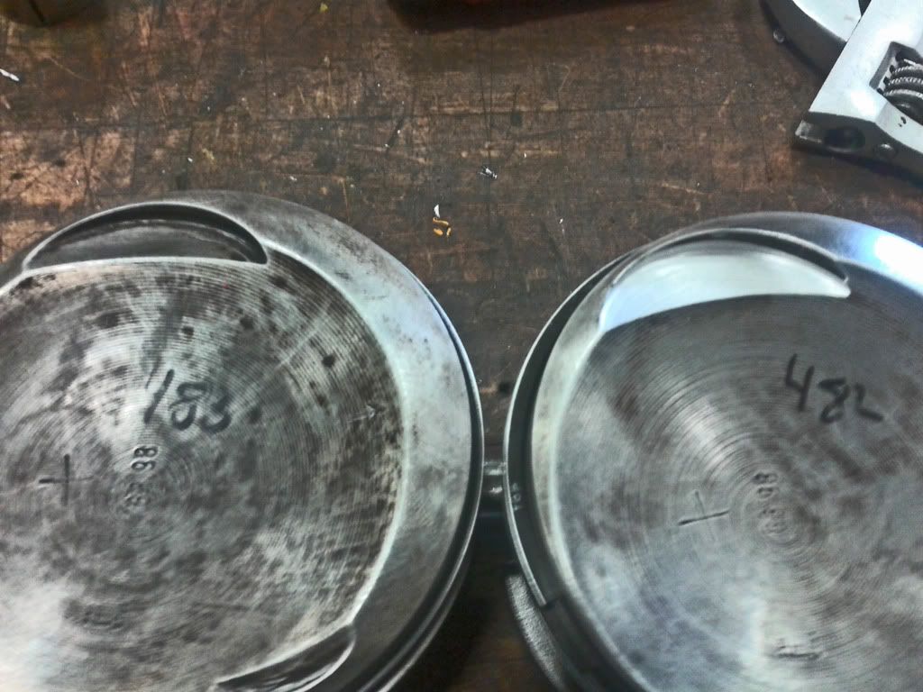
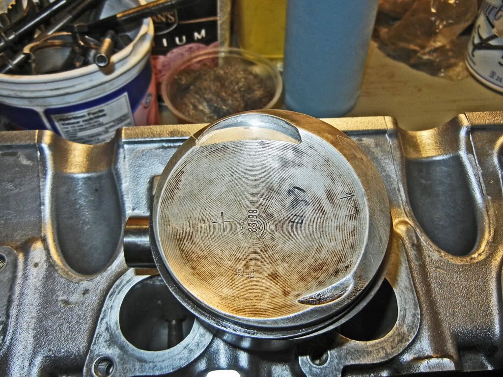
As you can see I didn't have the diameter set exactly to the relief diameter, but rather than having to brake the ghetto ass set-up on my cutting tool I opted to just clean up the edge with a rotary tool after the fact. Here's a couple pictures after I cleaned up that edge...
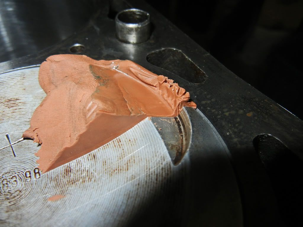
So this evening I slapped the bottom end back together and checked my valve to piston clearance. I was happy to see this when I cut through the clay...
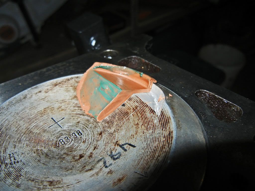
The clearance is now ~1.8mm
That's all for now.Leave a comment:
-
So thanks to digger I double checked the valve to piston clearance again yesterday using some clay and found that the exhaust side is ok, but on the intake side I only have a whopping 0.5mm or so which is far from enough and seems like far too little for Schrick to not specify that the 284 cam requires deeper valve reliefs. I'm going to double check the cam timing again tomorrow just to make sure that the cam gear didn't slip or anything causing the timing to advance. And if the VTP clearance is still too little I'll be pulling the bottom end apart so I can machine some larger reliefs for the intake valves.Leave a comment:
-
Good info. Thats the way i would do it to, but wanted to make sure. Can't wait to see this running. Will be building a similar stroker myself in the near future.Leave a comment:
-
I am using the old head gasket which has already been squished when and I'm not torquing the head bolts to spec, just snugging them down, there's no need to torque them.
Head warpage shouldn't be an issue, however just to be cautious I always loosen torqued head bolts gradually and evenly.
Schrick cam specs can be found here http://www.avl-schrick.com/dat/MK/Sc...202011%20E.pdf
Yes I am planning on using locktite or some form of sealant between the crank seal adapter and the crank.Leave a comment:
-
When you check p to v clearances are you using old head gasket and head bolt and torquing to spec? Is head warpage something to worry about when taking the head back off?
Are the peak timing numbers something schrick provided?
Are you using any kind of locktite for the front main seal adapter?Last edited by tinkerputzer; 05-24-2012, 01:25 PM.Leave a comment:
-
I remember checking the clearance at a few other points on the cam and the clearances seemed ok, but the only numbers I actually wrote down for some reason were at max lift, which you're right isn't the spot I need to be worrying about. I'll double check the clearance at TDC again tonight.
Thanks for pointing that out.Leave a comment:
-
unless you explained it wrong checking piston to valve clearance does not involve checking when valve is at max lift. you need to check either side of TDC as that is when the piston and valves are closest.Leave a comment:
-
Update:
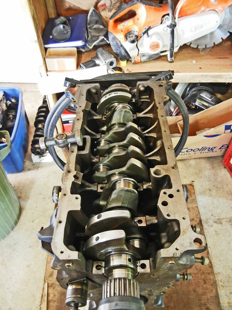
I've got the bottom end internals assembled now.
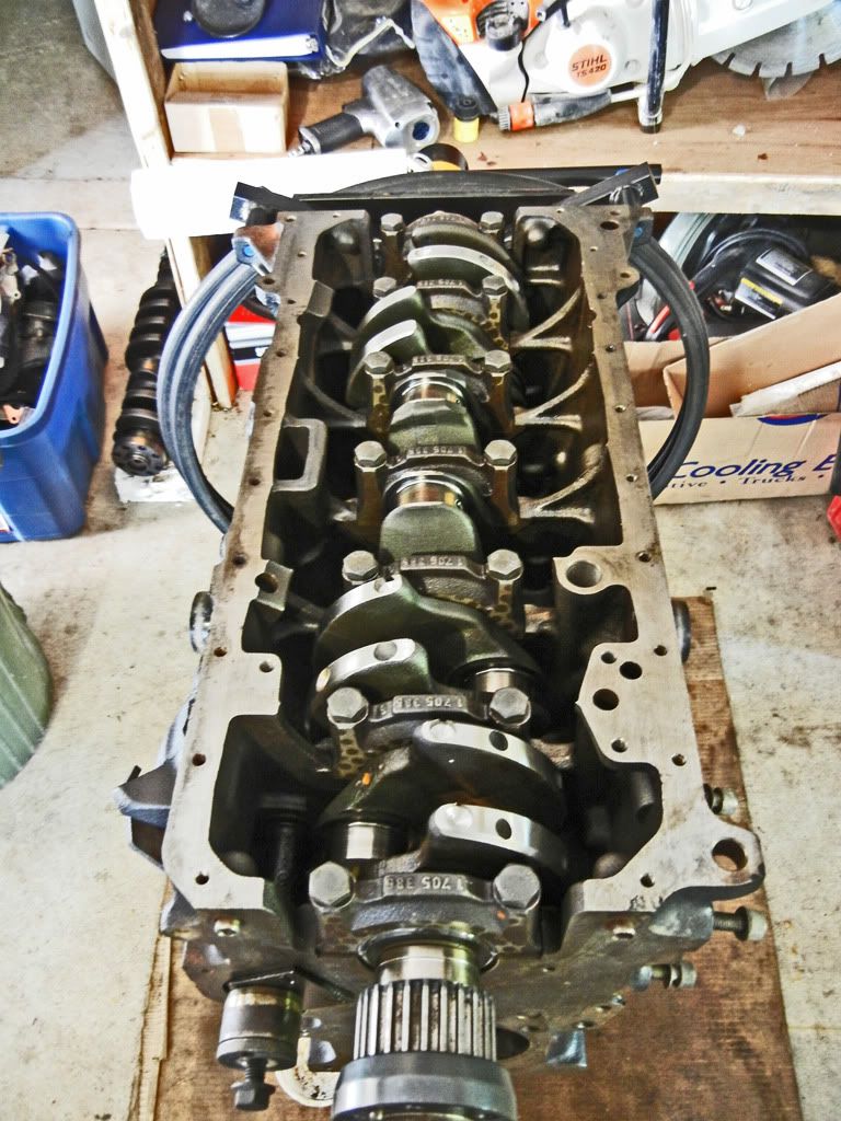
Bare block...
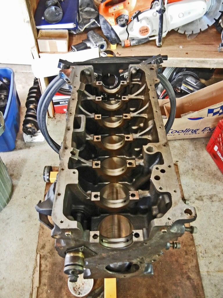
Bearing shells installed...
Crank dropped in (after putting a dab of oil on each shell)...
To check the bearing clearance cut a piece of plastigauge and lay it across the crank journal (make sure to wipe oil off the journal surface)....
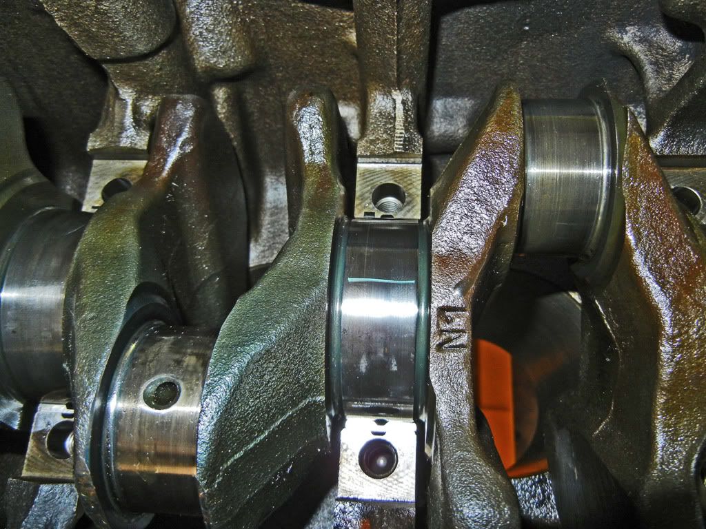
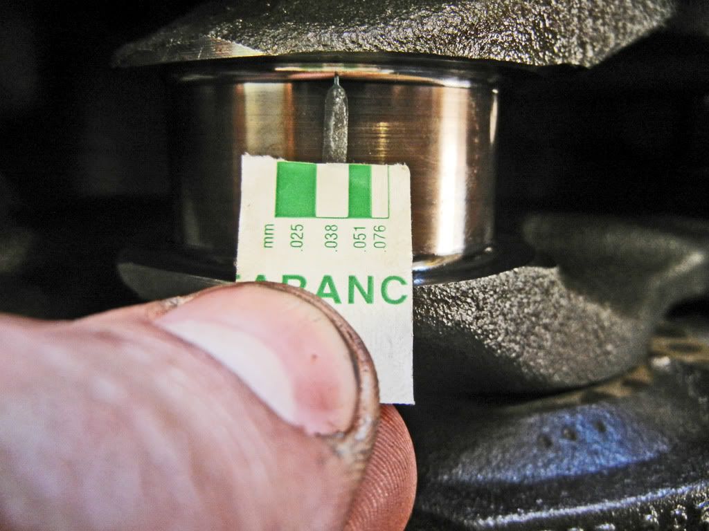
Then install the other half of the bearing into the shell. Apply a thin layer of oil to prevent the plastigauge from sticking to the shell. Then install the cap and torque the main bolts to spec. Then loosen the bolts off and remove the cap, all the while being careful not to rotate the crank at all. When you remove the cap you should see something like this...
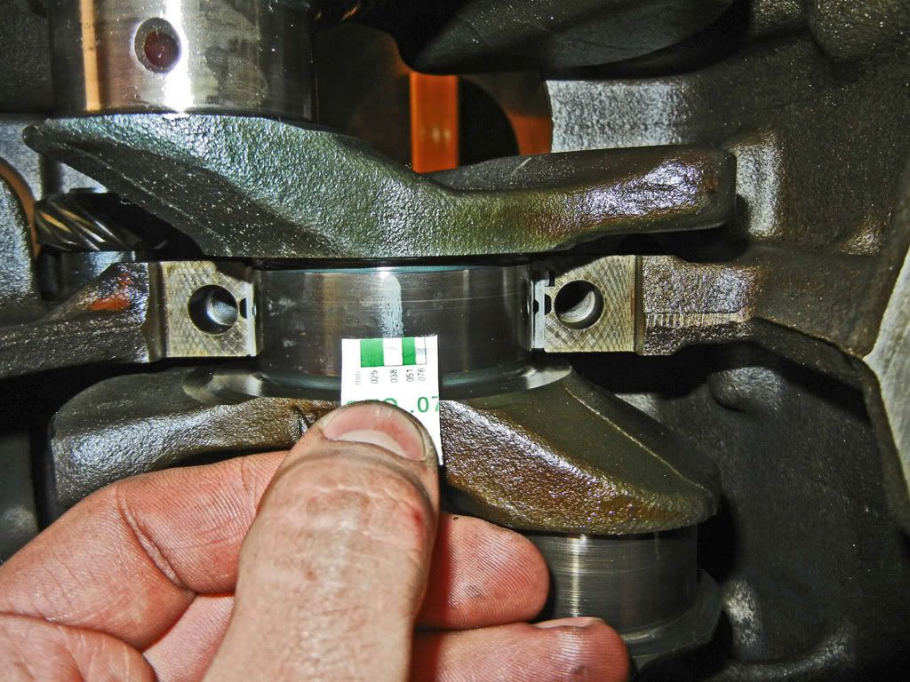
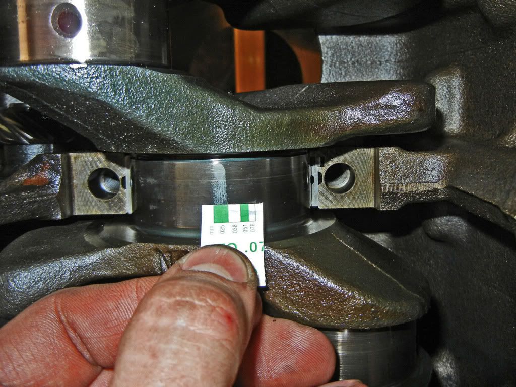
Compare the width of the flattened plastigauge to the scale that comes with the plastigauge to determine the bearing clearance. For a yellow classification bearing (which is what I have installed) the main bearing clearance is supposed to be 0.020-0.046mm. As you can see in the pictures above the plastigauge is wider than the 0.038mm bar, but not wider than the 0.025mm bar, therefore the clearance is between 0.025-0.038mm which is right on spec. Also make sure to keep an eye out for any taper in the width of the flattened strip indicating uneven wear of the bearing surface.
Then clean off the plastigauge from the bearing surfaces, oil up, reinstall, and re-torque the bearing cap. Do this for all 7 main bearings...
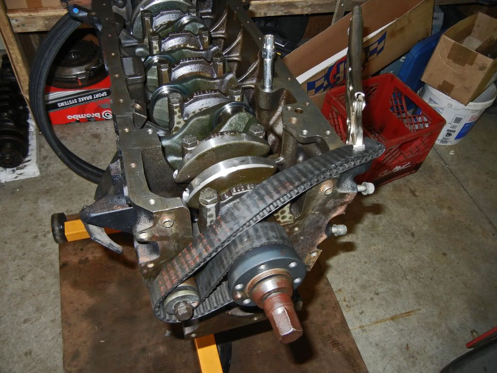
To check the rod clearances I'd rotate the crank to the position I wanted then use the timing belt and a pair of vise grips to lock the crank in place because I found it hard to keep the crank and rod from rotating during the process of installing the rod and torquing the cap on...
Repeat the same process for the plastigauge on the rod bearings...
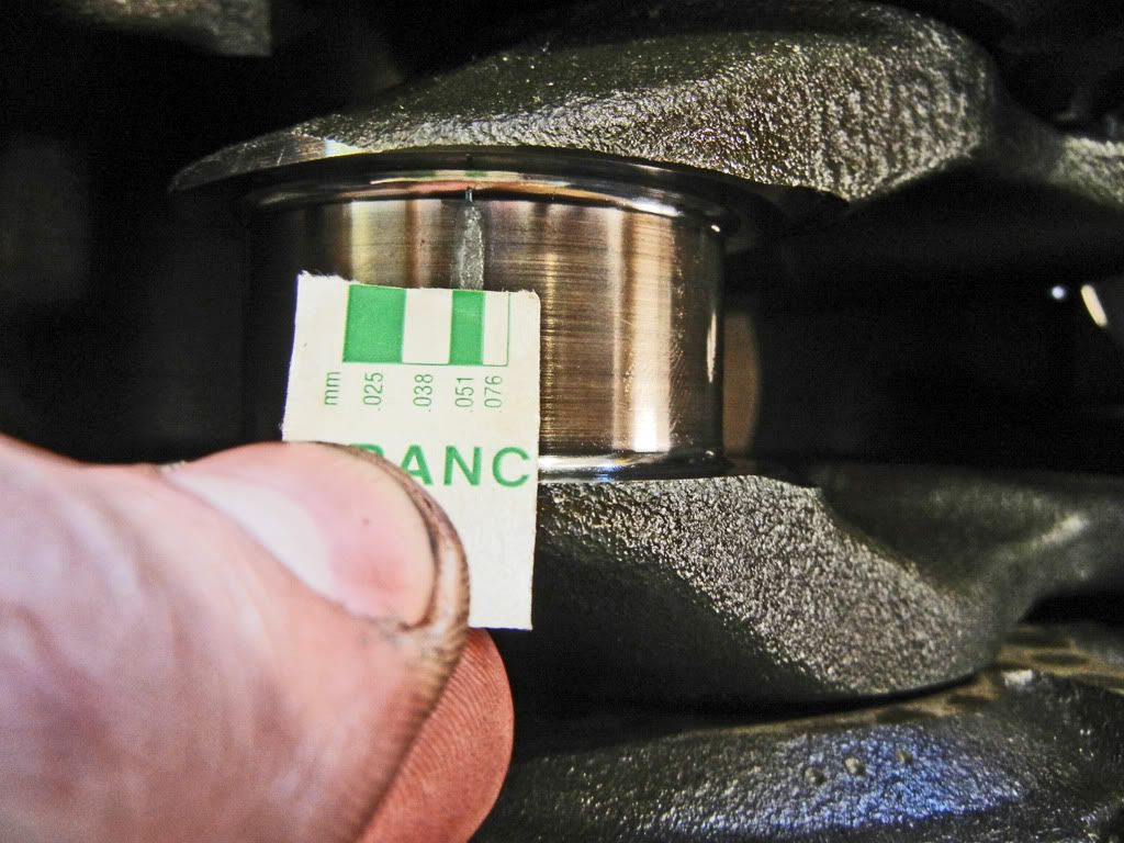
For the rod bearing the clearance for standard bearings is 0.030-0.070mm. As you can see above the plastigauge was wider than 0.051mm but narrower than 0.038mm so the clearance was between 0.038-0.051mm, once again right in spec.
Before I installed the rods and pistons I checked the balance of the rods. I checked all the wrist pin ends using this set-up...
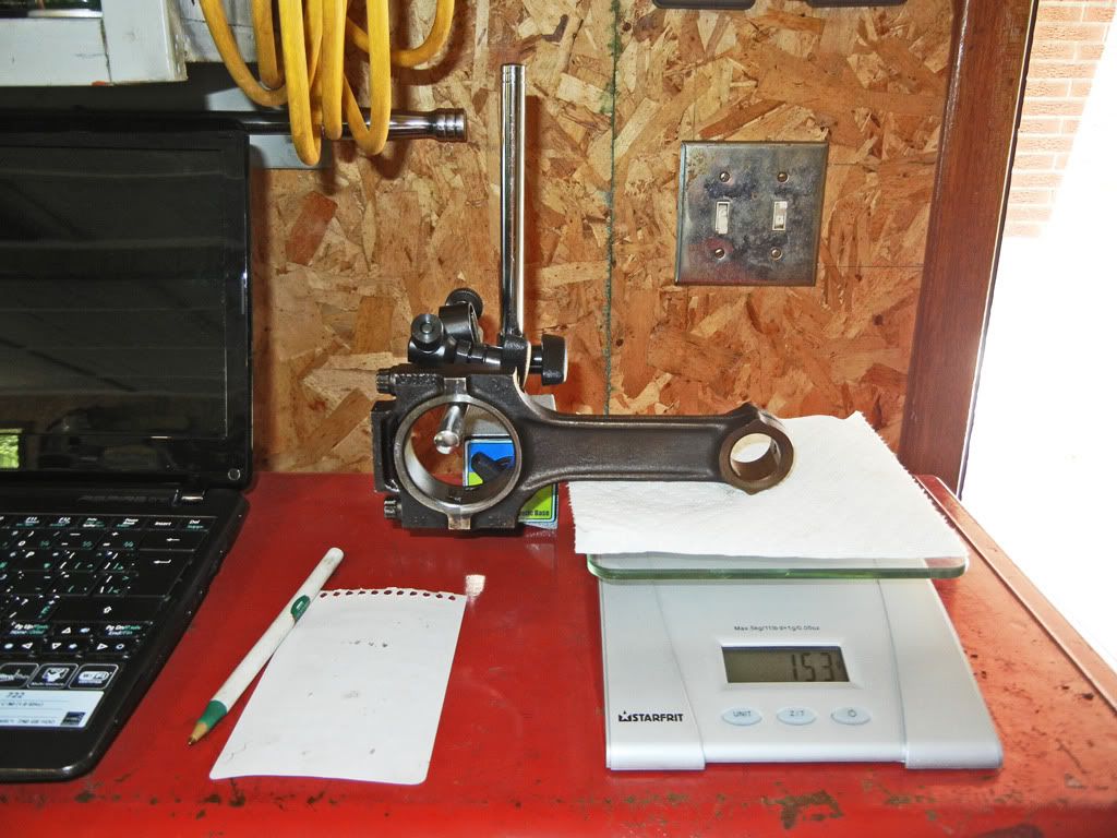
And then I checked the overall weights. The rods were all pretty much within +/- 1 gram of each other so I didn't fuss at all with balancing them.
I also checked the piston ring gaps before I installed them. Just pop a ring into a bore and use a piston to square it up, then use a feeler gauge to measure the gap in the ring. My ring gaps were right on the outer limit of the tolerance because after being de-glazed my bore diameters are on the outer limit of the tolerance.
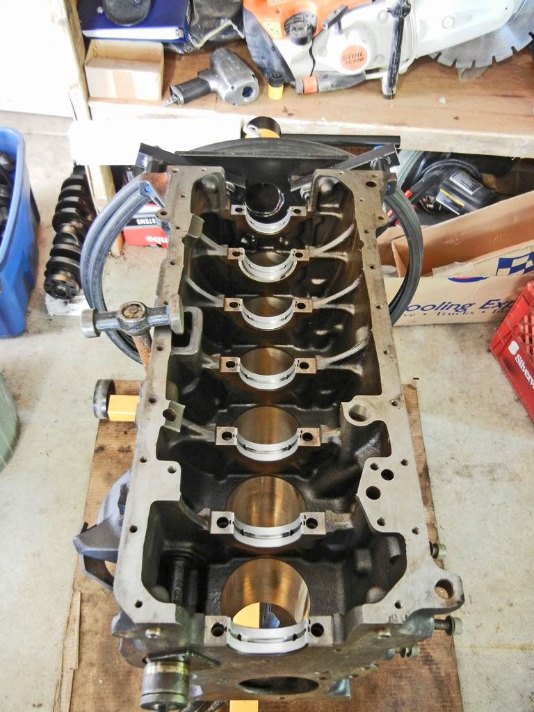
Installing the pistons is straight forward. Install the rings making sure the gaps are properly separated. Use a piston ring compressor to compress the rings leaving a bit of the skirt exposed so you can sit the piston in the bore...
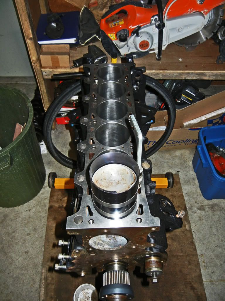
Tap the piston in until it pops out of the ring compressor...
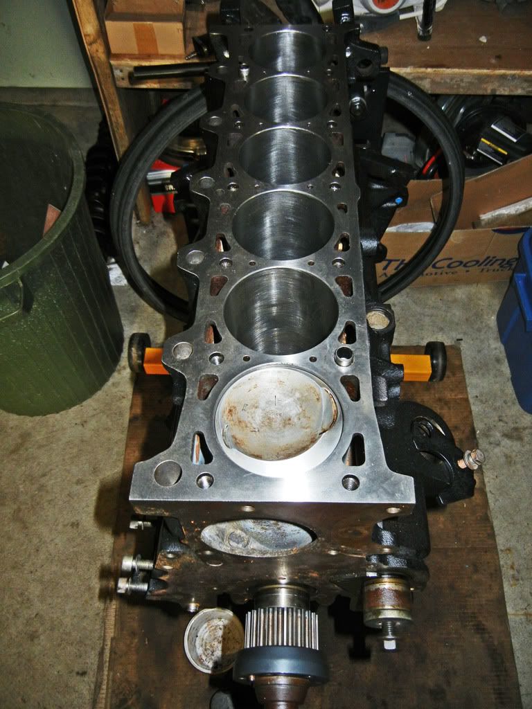
Then turn the block over, push the piston until the bearing shell seats on the journal, apply a dab of oil to the journal, install the rod cap and bearing, and finally torque to spec. Repeat 5 more times and your're done...
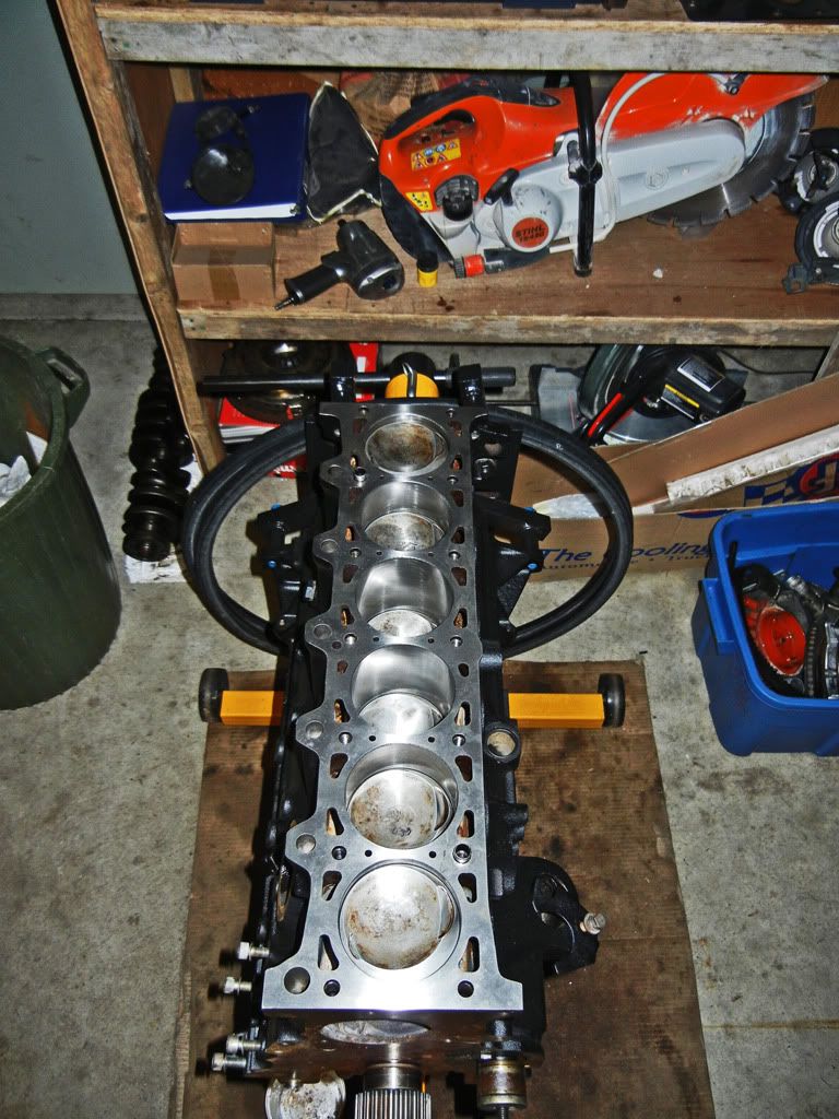
That's all for now!Leave a comment:


Leave a comment: