If this is your first visit, be sure to
check out the FAQ by clicking the
link above. You may have to register
before you can post: click the register link above to proceed. To start viewing messages,
select the forum that you want to visit from the selection below.
Pin number 9 is for tachometer goes to c104 ? in the glove box ( white flat-prong with 3 wire) Black wire is the one for tachmeter.
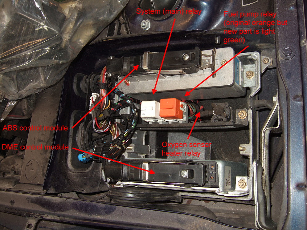
Round-plug with 4 wire = Oxygen sensor.
ok had a chance to go and look back at my notes and my adapter does not have a pin 13 but pin 14 ( i think you read the connector wrong ) and also the 3 wire plug in the glove box looks like it is the fuel pump out put from the relay to the pump its self. and the black lead looks like it is ether the tack signal to the cluster or the ac signal "on" to the dme. not to sure need to find a 318 in the jy and take a better look at it.
So only two relays, fuel pump relay is used also for o2 sensor heating sounds like. So my harness with 2 relays is okay after all, not missing a relay :)
"On 535i models the oxygen sensor heater relay is not used. The oxygen sensor heater is supplied with power from the fuel pump relay."
O2 sensor wires
1 - GE goes to pin 10 of DME
2 - SW goes to pin 28 of DME
3 - GND
4 - GN/VI
B201 cylinder id
GE pin 31
SW pin 8
B202 engine speed sensor
GE pin 48
SW pin 47
AFM (b two o eight) X152B connector
1 GR/VI
2 GR/GE
3 GR/WS
4 GR/BL
Here is where it gets interesting... found the E-Box Fan. It's using Pin 6 (GN/WS) of X20 (goes to pin 16 of D100 diag port)...and then goes to X1552 connector pin 2 for the M201 E-Box FAN.
Pin 5 of X20 (BR/GN) goes to connector X1526 pin 1 of Oil Pressure Switch B206, and also goes (BR/GN) to pin 3 of X1552 connector. Pin 1 of the X1552 (BR color) goes to B210 Temp Switch connector X1551.
Diagram
I didn't find or maybe I missed? The black 8 pin connector (with the 7 pins)... I still have no idea what it is.... I tried to find something with 7 wires, but most automatic and abs stuff had either too few or too many. I wish I knew the name of the connector on the harness then I could look for it in the PDF.
If this thing doesn't fire up as soon as you turn the key after I spend my weekend holding your hand through the swap I'm gonna hold you down and let Cameron fuck you in the ass.
am I on crack or am I reading this wrong? why does this diagram show 3 main relays?
but if you confirmed that there is only 2 relays? k201, k202 and last k203?
oh wait that diagram is for a 525 not a 535.... I need to stop doing drugs lol jean I would be willing to bet you can just by pass the green wire at the c104(glov ebox) with the on that is going to the c103 (fuse box)


Comment