Maf options?

Collapse
X
 
  • Time
  • Show
Clear All
new posts

  • coffeeandcigars
    replied
    Quick Update: after playing with the transfer curve and limiting the DAC Output to the ECUs AFM Input to around 4,8-4,9V it got rid of the abrupt leaning out at 5700 rpm.
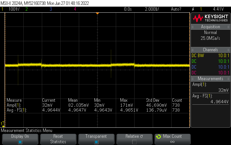
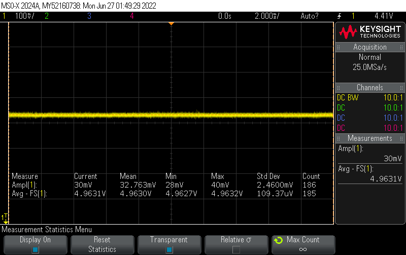
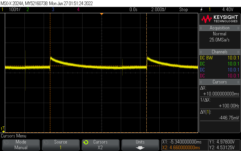
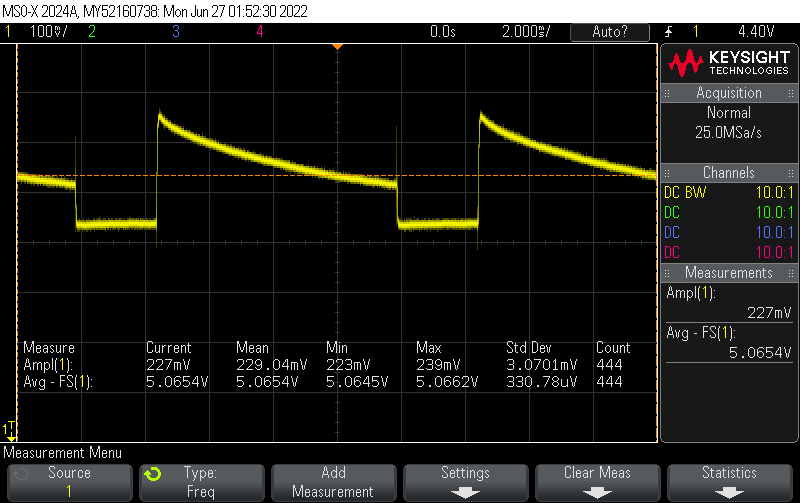
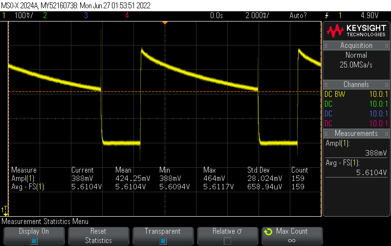
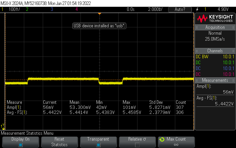
    Somewhere around 4,9V seems the max that the ECU in my case accepts and yields therefore my max IPW i think i can reach. It wants to command up to 5,1V
    As the graph shows its still way to lean up top. I would like to see at least 13,5.
    Click image for larger version

Name:	AFR at 95% fuel.png
Views:	181
Size:	168.5 KB
ID:	10062946
    The next logical step would be to learn how to burn chips and alter the fuel maps itself thought of upping fuel pressure but that creates a whole other heap of problems

    Leave a comment:


  • coffeeandcigars
    replied
    Yeah the bolts on the vac-manifold rattled loose. And after another round of testing and further investigating i found the top surface of the VAC-Manifold to be underextruded and therefore leaky. Will need some Epoxy for futrure but spraypainting the surface helped a ton also.
    Its now able to idle with functioning lambda regulation. But its still fighting hard and not always suceeding.

    In this Graph are plottet AFR over RPM warming up from 31 to 95°C:
    Click image for larger version

Name:	AFR-Hits.png
Views:	190
Size:	453.4 KB
ID:	10062287
    Way to many hits above 14.7 but a world of difference to before.


    This is some of the logged data of the complete Warmup (15 mins of data):
    Click image for larger version

Name:	Warmup Graph.png
Views:	190
Size:	272.1 KB
ID:	10062288
    From this i noticed that my calculated AFM_sim_voltage has very little resolution at idle. I have a hunch the math (lots of floats) i am doing is causing loss of res. Need to investigate...

    This one is a closer look at hot Idle lambda control:
    Click image for larger version

Name:	warm idle detail.png
Views:	182
Size:	97.3 KB
ID:	10062289
    I think my RPM signal is not very accurate here, jumping too much...problem for another day.
    The AFR is oscillating as i would expect but with way more amplitude than i am used to from the M52 . And its still going full lean every couple seconds.
    Its a shame that INPA isnt working...i would love to see what the ECU is doing for STFTs and LTFT right now ECU is propably like: "Help me understand"

    As for driving, heres a WOT-Pull with a lets say "interesting" behaviour:
    Click image for larger version

Name:	WOT going lean.png
Views:	188
Size:	251.9 KB
ID:	10062290
    This time its going full lean at 5700 for some reason...until then it at least feels ok and pulls good. But looking at the AFR curve its pretty bad. Complete level shifts from run to run but always the same U-shape with the richest point at ca. 4100 rpm.
    I think i need to verify that the DAC Output is behaving as expected after 5700. Have to free up a analog pin and log the actual generated Voltage as well.
    And also check if changing my transfer curve has actually an effect on the AFR-curve Well it never f***in ends...

    Leave a comment:


  • bmwman91
    replied
    Good progress there! And yeah, definitely fix any first-order stuff like vac leaks before trying to tune anything!

    Leave a comment:


  • coffeeandcigars
    replied
    Still alive
    Got the wideband in today and went for a quick testdrive.
    Click image for larger version

Name:	IMG_20220708_193931_.jpg
Views:	200
Size:	57.5 KB
ID:	10061280

    Resistors on the Ref line, diy-IAT and MAF-converter active. The intake sound at WOT without the AFM is getting in the right direction, i can hear ITBs
    Click image for larger version

Name:	IMG_20220627_115323_.jpg
Views:	186
Size:	56.1 KB
ID:	10061282
    At idle its over 20 AFR, so i need to check for vacuum leaks once again. But driving normally it holds it at around 14.7 AFR.
    WOT is sometimes more in 11.8 range and sometimes 12.5 not superstable here (I was adding 5% to the Airflow signal across the board for safety)
    Click image for larger version

Name:	IMG_20220708_203050_.jpg
Views:	184
Size:	58.0 KB
ID:	10061281
    Maybe tomorrow i will have the WBO2 output included in the logger to do some pulls and driving to see whats up. I may start playing with the transfer curve for fun but the vac-leaks really gotta be fixed before going further.

    Leave a comment:


  • coffeeandcigars
    replied
    thats pretty crazy that the Ref went up to 5.6V when unplugging stuff on yours! And that the IACV has such an impact...

    I need to think of a better way to only connect the Ref to my converter when its is below the Arduinos operating Voltage to not fry stuff when i have something unplugged in during testing!

    Leave a comment:


  • bmwman91
    replied
    I did some tests with my oscilloscope and found interesting results.

    I do not see indications of regulator oscillation / instability, but it is definitely dependent on the output load for keeping its voltage within spec. The idle control valve (ICV) shows a lot of effect in the cleanliness of the voltage waveform. However, I do not think that the ICV is the only thing that would do this. Since the engine was not running, the ICV is the only device drawing significant current. I would be willing to bet that the fuel injectors & ignition coils also have an effect. The interference is really only a major thing if there is little/no load on the vref line. So, it looks like putting a resistor between it and ground is a good idea when eliminating the AFM or other devices which normally draw current.


    Here are some scope shots and descriptions. In all cases the car was in accessory mode and not running the engine.

    Everything connected. The little 100mv spikes are actually from the ICV, probably EM interference with the scope probe. You can see that there is a very slight "step" in the voltage, which is also due to the ICV, but seemingly more due to effects in the ECU.


    After unplugging the ICV.


    Next I plugged the ICV back in and unplugged the TPS. This led to a minimal change in the average voltage, but the current draw from the ICV was making a much more pronounced effect visible.


    I know that it is the ICV both because unplugging it eliminated this effect, and the fact that it is a 100Hz frequency which is what the ICV operates at.


    Next, I plugged the TPS back in and unplugged the IAT thermistors. Things got ugly this time! The behavior was inconsistent in that the first time I did it, the average voltage jumped to ~5.3V. At one point the probe moved and grounded the Vref line on the intake manifold (oops?). After power cycling the ECU, the average only increased to ~5.06V. Anyway, the ICV makes its presence known for sure lol.


    Thermistors + ICV unplugged. Voltage seemed to return to normal.


    With the MAF converter unplugged, the value jumped to ~5.6V.


    Unplugging the ICV cleaned the signal up a bit, but the average was still 5.44V. Funny enough there is still a ~100Hz waveform present, which I assume has to do with current consumption by the driver IC for the ICV. Strange.

    Leave a comment:


  • bmwman91
    replied
    I meant TPS...there has not been an AFM in my car for more than 10 years lol. Anyway, I tried unplugging stuff and checking the output. With the IAT thermistor unplugged, the voltage went to ~5.5V, and with my MAF converter unplugged (which includes the IAT thermistor) it jumped to 6.25V. Removing the TPS plug caused it to go from 4.97 to 4.975V. So it would indeed seem that some minimum load is needed.

    After the car cools off I will see about pulling it in to my garage and getting my oscilloscope on the reference voltage. I have seen voltage regulators become unstable without proper capacitance on the output, and it is possible that a minimum load is also needed in this case since there is very minimal capacitance provided on the ECU main board.

    Anyway, it sounds like having some amount of dummy load placed on the line is necessary!
    Last edited by bmwman91; 06-25-2022, 03:41 PM.

    Leave a comment:


  • coffeeandcigars
    replied
    Its very strange indeed!

    Originally posted by bmwman91
    I went out and checked the voltage and it was 4.977V with and without the TPS connected.
    Thanks for confirming what yours does! (Did you mean AFM instead of TPS? My TPS was always plugged in during this but maybe i should try unplugging that and see if something changes as its also loading the Ref Voltage)

    Originally posted by bmwman91
    The little circuit inside your AFM is just a little active low-pass filter. You must have a newer version of the AFM since I have only ever seen that little circuit inside of an adapter thing that goes between the AFM and harness. Supposedly the M42 had some idle stability issue that required this to smooth it out, although I've seen no difference in how the car runs with or without it when I had an AFM in there.
    Oh ok =) then it should be like the schematic after all

    Today I went over everything again checking all my sensorvoltages...

    stock (AFM plugged in, Converter disconnected):
    Ref=5,006V; TPS_closed=0,685V; TPS_wot=4,255V; AFM=0,252V; IAT(in AFM)=3,194V; ECT=3,485V

    MAF (Converter disconnected, no resistor):
    Ref=5,276V; TPS_closed=0,722V; TPS_wot=4,487V; MAF=0,025V; IAT(my own)=3,236V; ECT=3,482V
    ->makes sense to me that TPS reads higher now

    MAF (Converter disconnected, with 358 Ohm Resistor):
    Ref=5,012V; TPS_closed=0,686V; TPS_wot=4,249V; MAF=0,025V; IAT(my own)=3,222V; ECT=3,479V

    Do you think its worth opening the ECU and start poking around to see if anything obvious has let the smoke out?

    After measuring everything i put everything back to just IBTs with all stock sensors and ran it. It was absolutely the same as ever...

    Leave a comment:


  • bmwman91
    replied
    Strange, I have never seen the reference voltage change. Pin 23 of chip S600 in the ECU provides the output, and as far as I would imagine it is a regulated output. I went out and checked the voltage and it was 4.977V with and without the TPS connected. I have my MAF converter connected as well, but it draws nearly zero current from the Vref line.

    The ECU makes no measurements of the Vref line to determine faults as far as I am aware.

    The little circuit inside your AFM is just a little active low-pass filter. You must have a newer version of the AFM since I have only ever seen that little circuit inside of an adapter thing that goes between the AFM and harness. Supposedly the M42 had some idle stability issue that required this to smooth it out, although I've seen no difference in how the car runs with or without it when I had an AFM in there.

    Leave a comment:


  • coffeeandcigars
    replied
    Yeah its tricky! And you already got a pretty optimal setup for it.
    I gave ABS another try with the IAT sensor housing after we talked about it and the overhangs were pretty bad. I guess the parts i printed in the past with ABS coped better with its drawbacks...

    This is said IAT housing, the underside looks like dogs**t I think for V2 i will use the Polymaker PA6-GF...


    The interesting thing happened when i unplugged the AFM (before it was always inline, just depinned #2) and tried to use the MAF and diy IAT sensor.
    I noticed that the Reference Voltage from the ECU was not the rocksolid 5,00V it always was. I got a reading of 5,28V which messed up my readings of TPS, IAT etc.
    Next thought was that the ECU wants to see the load from the AFMs resistor track (for the wiper) according to this schematic:
    Click image for larger version

Name:	IMG_20220526_212615_.jpg
Views:	237
Size:	47.1 KB
ID:	10059599
    I measured 356,3 Ohms across Pin 1 and 5. And when plugged in the Ref Voltage is correct again...
    Okay so why not put that resistance between Pin 1 and 5, maybe the ECU will be happy again. And yes the Ref. Voltage measured 5,0XX V again with a resistor combination of 358 Ohms.
    At this point i am thinking to myself why the hell would a missing AFM impact the power supply circuit for the Ref. Voltage so much, very sus. The TPS is fed from the same ref Voltage, just has a different GND Pin on the ECU.
    Then i had a look at opened AFMs online...there is some sort of circuit in there. I guess its something to do with checking the resistor track quality or just generating/filtering the AFMs output just guessing at the moment
    But that schematic with just resistive elements is obviously not the whole picture here!
    Click image for larger version

Name:	p13ZN1x.jpg
Views:	276
Size:	113.3 KB
ID:	10059600
    Maybe the ECU has the ability to determine the health of the AFM and TPS by measuring the resistance/presence of their wiper tracks? But this doesnt explain the shift to 5,28V when the AFM is missing...
    Questions over questions....and i thought this was the homestrech with just calculating volume airflow based on also IATs

    Have you also had this voltage shift on the Ref. Voltage when you removed your AFM?

    Leave a comment:


  • bmwman91
    replied
    Thanks for the suggestions. The FFCP is mostly enclosed, and I think it is at least 40°C inside. Bed is 110°C. The curling on overhanging corners is pretty bad during prints. I am using 0.2mm layers. It has 5 perimeters, so I do not think that is too muck of an issue. Cooling is disabled entirely. Anyway, it's mostly just a cosmetic problem so for now I can live with it. Now I know why so many people do not like ABS!

    Leave a comment:


  • coffeeandcigars
    replied
    Originally posted by bmwman91
    Male pin housing (AFM side): 12521718125
    Female terminal housing (harness side): 12521718126 (old PN was 12521737668)
    Female 2.5mm terminal: 61131376202 (TE/Amp PN 929970-1)
    Male 2.5mm pin: 61131376191 (TE/Amp PN929963-1)
    Wow thats awesome, thanks a ton, i ll try and oder one to make the adaption look nice in the bay!

    Originally posted by bmwman91
    The parts for it need to be ABS, and up until recently I had only worked with PLA. ABS had a bit of a learning curve, and while I have no issues with warp or adhesion, it is really tough to get good quality outer perimeters on ~45° overhangs, especially when the overhang is near a corner...the ABS seems to shrink and pull in which looks nasty. Any pro tips?
    Wouldnt call myself pro the only settings i had to dial in myself was for the Nylon stuff, otherwise the Prusa settings got me mostly good results.
    ABS shrinks a lot so its key to control/eliminate differential heating/cooling of the part as much as possible. It was also the material i used the "enclosure" (Cardboard-box) for because of the warp and the bed at 100°C to get ~40°C in the enclosure.
    For what you describe i think i would try to use a smaller layer height for the overhanging sections. That way the extrusion has more to "hold on" to below it and less power to pull.
    Also the wall thickness cant be to little or it would curl up on me.
    Imho it would be best to lay the new layer down after the one before has done its shrinking/cooling and is solid/stiff enough to hold its shape when the new layer on top does its shrinking->maybe printing way slower in those sections?
    A Voron is an awesome machine! They look superstable/precise with those linear rails *wobbly prusa mini in the corner of my desk*
    ...and the speed at which some guys print race benchys on them is crazy!

    Leave a comment:


  • bmwman91
    replied
    The air box 'upgrade' was just an idea I had while waiting for my 2.1L engine to be built...I sort of doubt that the stock air filter was restricting anything lol.

    I got the 4-pin connector from an old M42 O2 sensor and a spare M42 engine harness that I got cheap on eBay a long time ago.

    As far as the 7-pos connector system, it is made by Amphenol, but as far as I can tell you can't buy the parts from electronics distributors anywhere. There are BMW PNs for the housings though, since they were used as part of the fuel injector wire harness on various old 6 cylinder engines. Here's what I have found for those:
    Male pin housing (AFM side): 12521718125
    Female terminal housing (harness side): 12521718126 (old PN was 12521737668)
    Female 2.5mm terminal: 61131376202 (TE/Amp PN 929970-1)
    Male 2.5mm pin: 61131376191 (TE/Amp PN929963-1)
    I have not been able to find the rubber grommets for these unfortunately. I think that 12521737944 might fit, but I do not know for sure.


    And yeah, I have a small 3D printer too. It's an old Flashforge Creator Pro that I have modified a little (Micro Swiss all metal hot end, removed 2nd extruder, TMC2209 stepper drivers, lots of brass shims jammed in places to eliminate guide rod wiggle in the plastic holders, BuildTak Flexplate system). I am actually using it right now to print the parts for a Voron 2.4r2 that I will be building this summer. I've wanted a larger build volume and modern features for a while now. The parts for it need to be ABS, and up until recently I had only worked with PLA. ABS had a bit of a learning curve, and while I have no issues with warp or adhesion, it is really tough to get good quality outer perimeters on ~45° overhangs, especially when the overhang is near a corner...the ABS seems to shrink and pull in which looks nasty. Any pro tips?

    Leave a comment:


  • coffeeandcigars
    replied
    Thanks for the pictures of your setup!

    ...so you DO have a printer already

    Was the filtersize a limiting factor on power for you?

    Things have slowed down for me a lot...
    I finally found a supplier where i could order some thermistors that are close, what an ordeal that was
    Still waiting for the pins to do the WBO2 harness.

    Been looking into how to do the wiring decently clean and without disturbing the original harness too much. Do you by chance know what type/manufacturer the AFMs stock 7 Pin connector is from. I thought of getting the AFM side connector to wire in the MAF and IAT and have it looking stock-ish (similar to how you did the IAT). But i had no luck finding out what type this is. BMW sells the side i already have on my harness (# 12521737668)

    The one you used for the IAT sensor looks like the MAF connector on my Siemens MAF (4-Pin). Where did you find the male part of that? Is it this one # 61131393773 ?

    Leave a comment:


  • bmwman91
    replied
    Here's how my thermistors are mounted (I used 2 MuRata ones, one for the ECU and one for the converter, although I could have just used the one for the ECU). You can see it part way down in this post of mine:


    I converted to an M30 air box since it uses an air filter that has ~75% more surface area while also being the same width as the original M42 filter box. It required some minor welding modifications to the PS reservoir bracket, but nothing major.

    Leave a comment:

Working...