
Originally posted by The Dark Side of Will
View Post
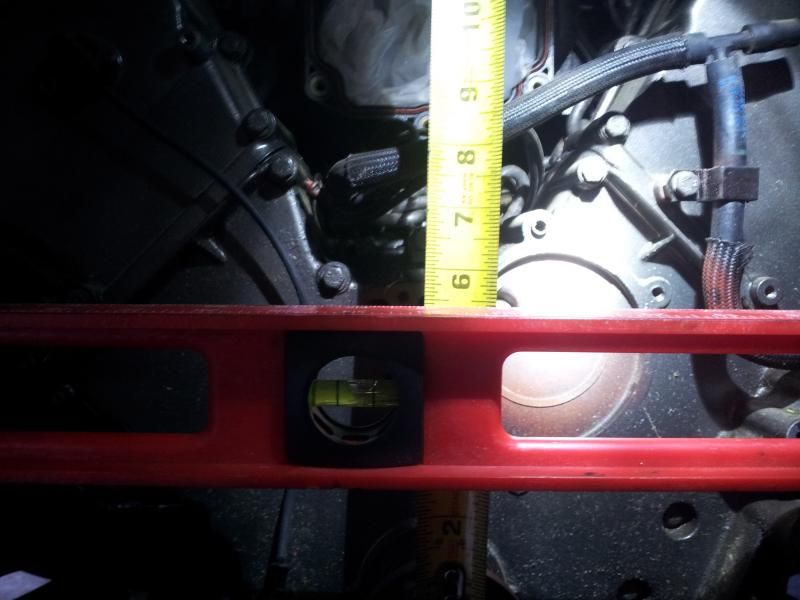
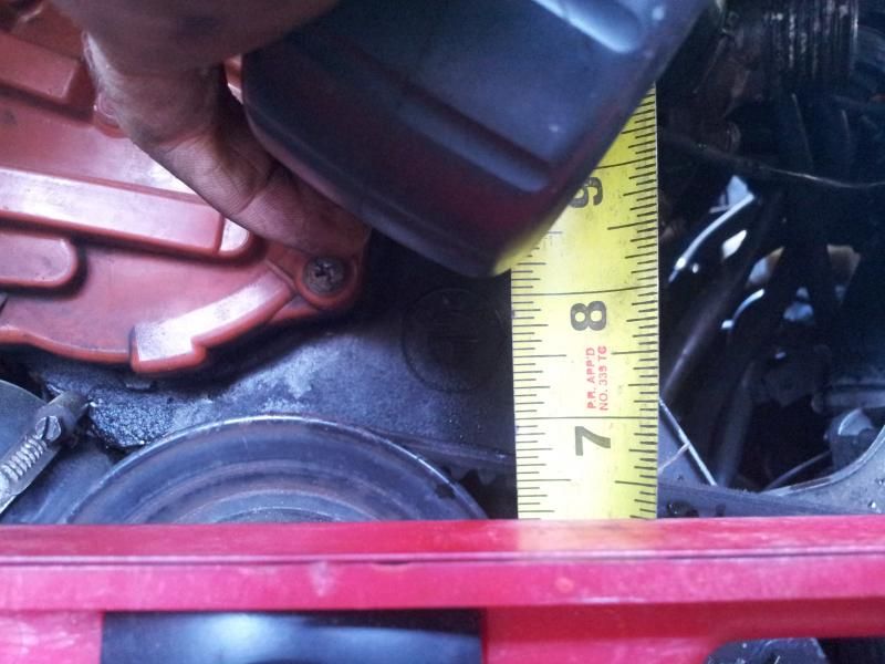
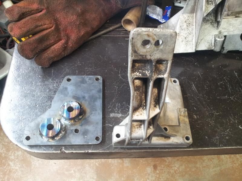
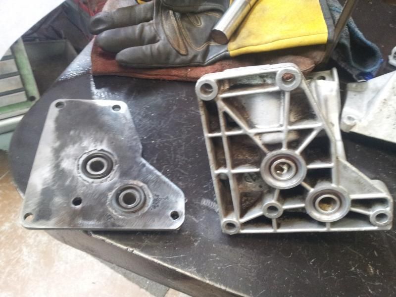
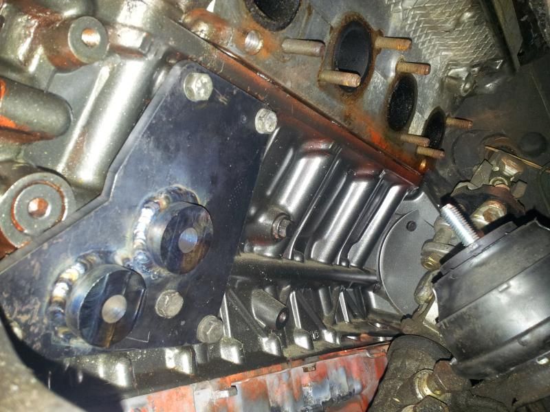
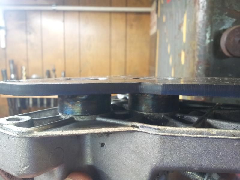
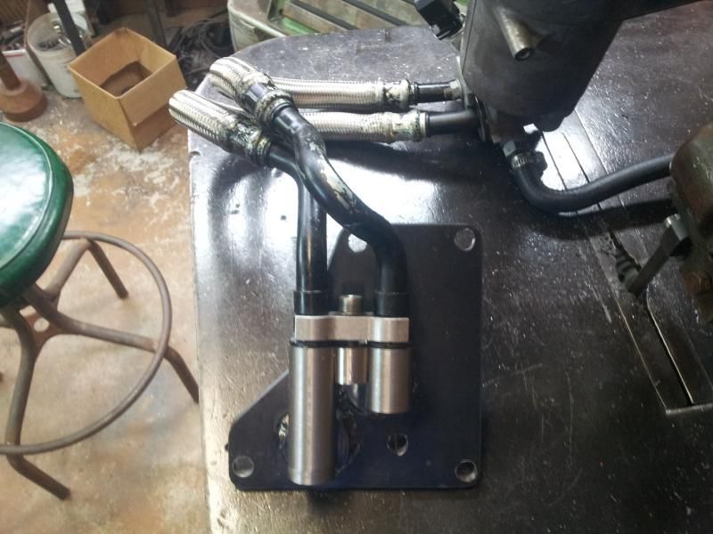
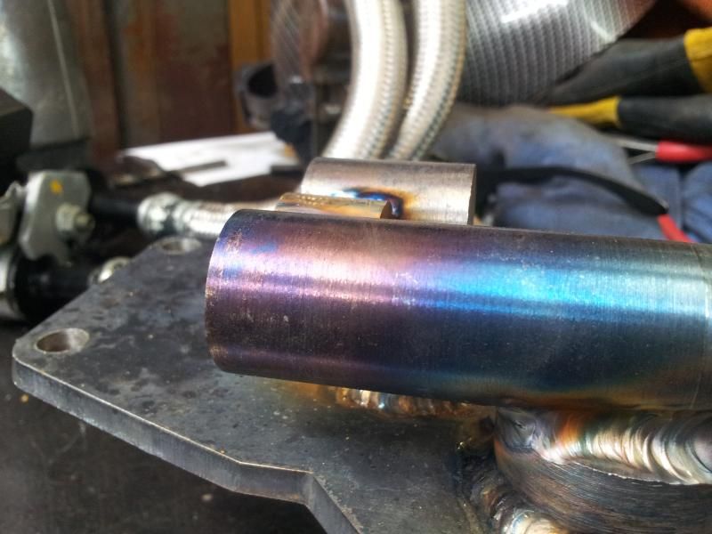
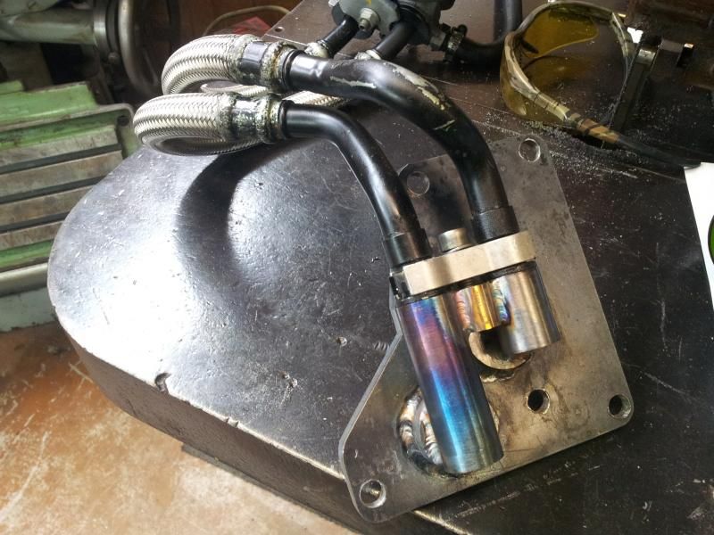
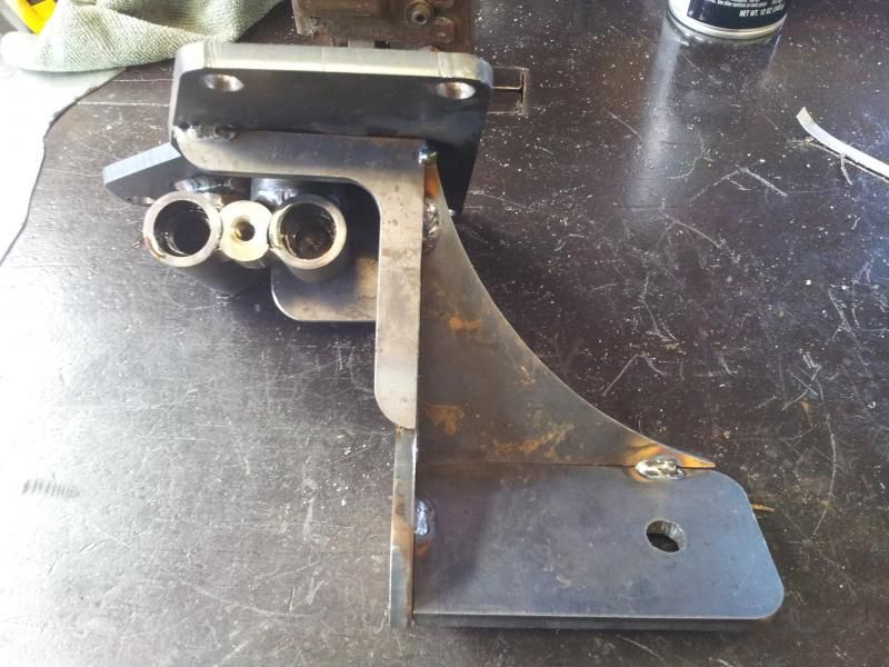
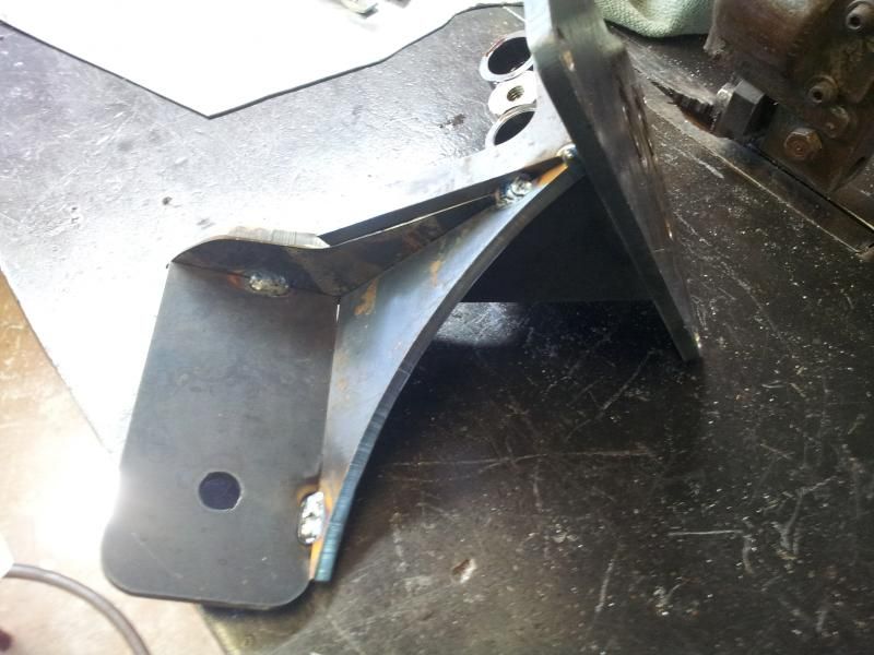
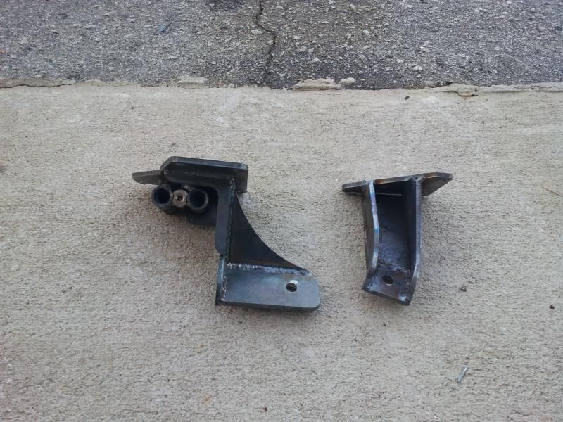
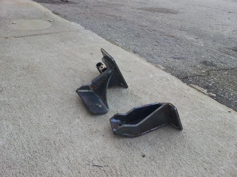
I've seen a few in person. Without notching the pan the mounts people have been using maxes out the inner control arm ball joint angle. Yes you can drive your car like that but its a matter of time before it causes premature failure.
Our shop prefers to keep the suspension geometry as close to stock as possible because we know that it holds up 20+ years safely in that configuration.
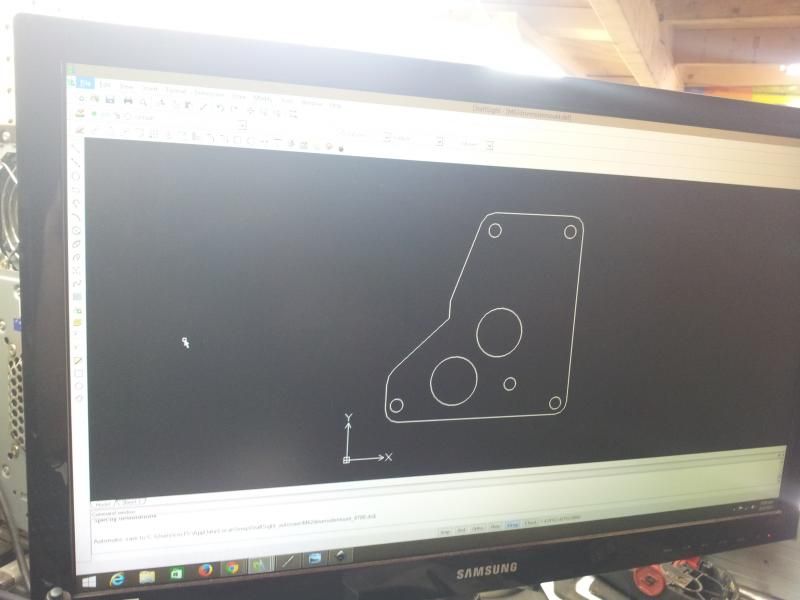
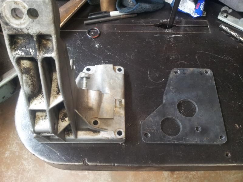
That said we consider notching the pan to be a better solution to getting the engine into the bay mounted with the correct drivetrain alignment.


Comment