If this is your first visit, be sure to
check out the FAQ by clicking the
link above. You may have to register
before you can post: click the register link above to proceed. To start viewing messages,
select the forum that you want to visit from the selection below.
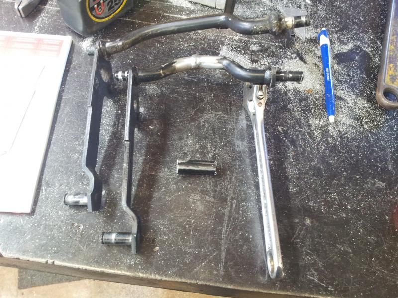
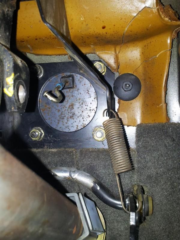
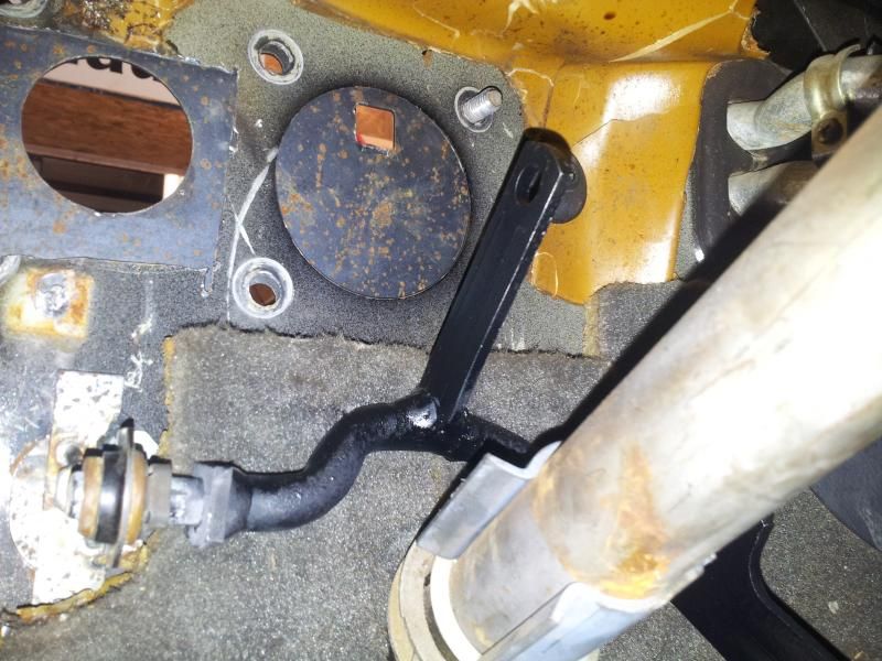
hey guys, made a little more progress on the braking setup. The goal was to keep oem vacuum assist brakes. Since we have already covered the mounting of the booster ill start with the pedal set modification as well as the lever that mounts on the firewall.
Seemed like once i moved one thing, everything else had to be modified. Thats the fun of this i suppose.
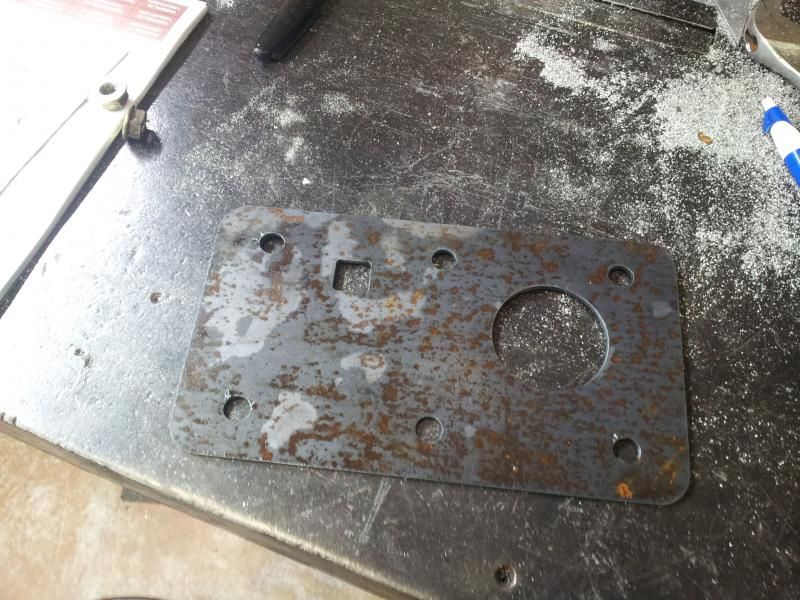
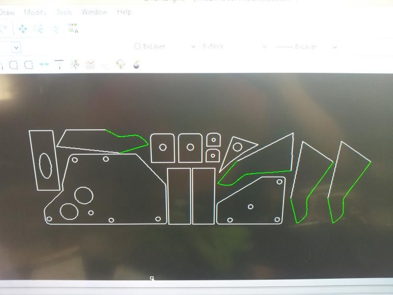
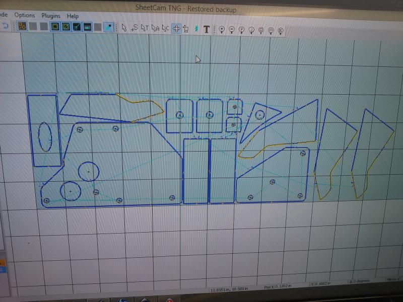
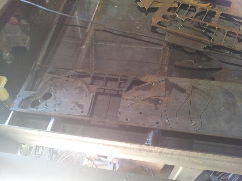
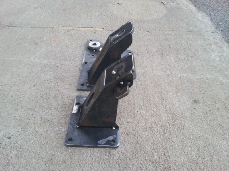
Custom made plate, just bolt it to the factory location and drill the remaining 2 holes. When i was prototyping this i cut the hole a little large. And it looks like a neanderthal with a butter knife cut it out.
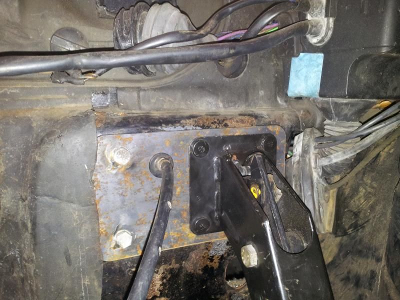
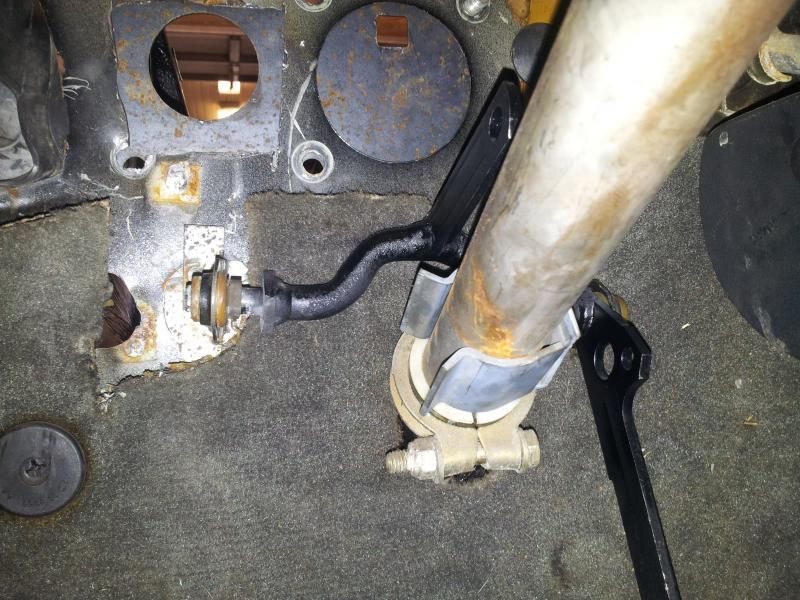
Once the plate was installed i was able to get my dimensions for the lower bracket. While i was making the bracket i realized it kinda looks like dickbutt lulz.
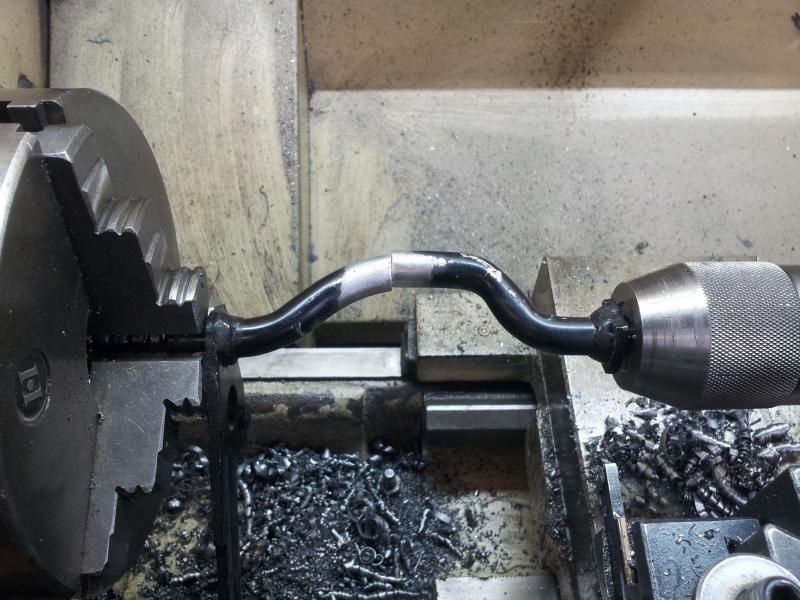
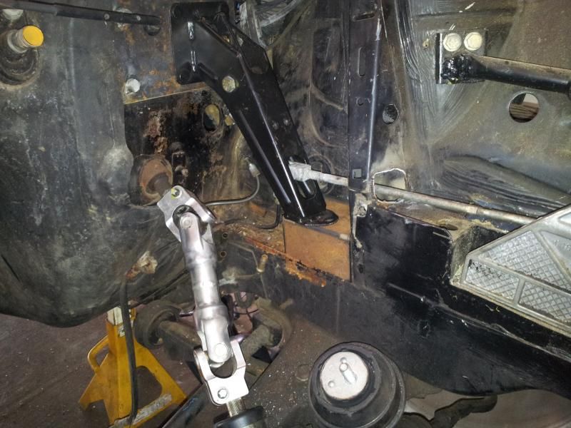
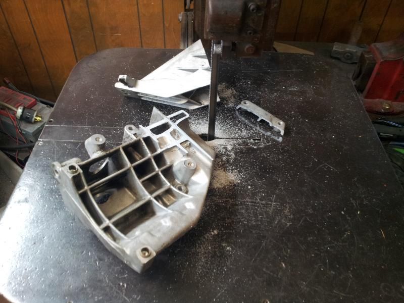
Heres a inside shot of it, again...pardon the horrible cut out. You can also see my modified throttle linkage. Which ill cover next.
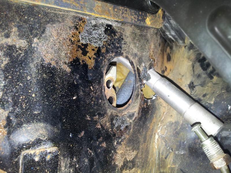
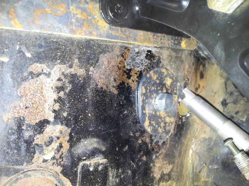
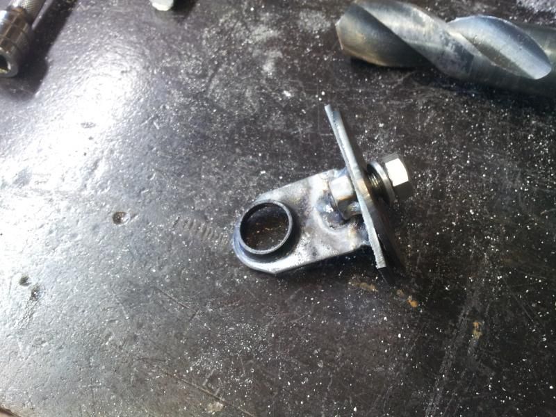
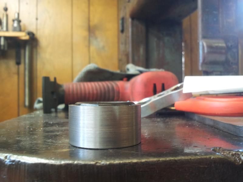
The throttle linkage is aluminum, I was able to cut a section of it out, once i did that the stock location wouldnt work. So my next job was to cover the vacant hole that the clutch cylinder was removed from. Luckily i was able to design a bracket that would kill 2 birds with one stone.
The bracket is a sandwich of 2 pieces of steel, So it can be left this way or welded it. Its pretty damned tight once the bolt is snug. Plus it gave me a little bit of wiggle room.
Yeah, this dude got skills. Matt, I'm gay for your plasma table and computing prowess.
@driveline angle… Who gives a fuck if the driveline angle is best or not on someone else's build? Let people experiment. That's how better ideas can emerge. Not saying they do every time, but still.
Well, got a little bit of work done today. Felt like crap, bleck.
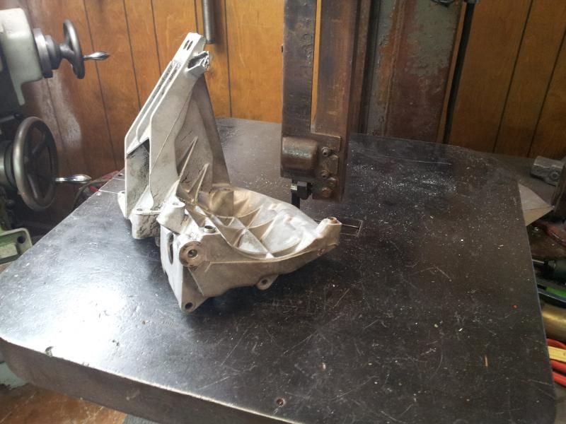
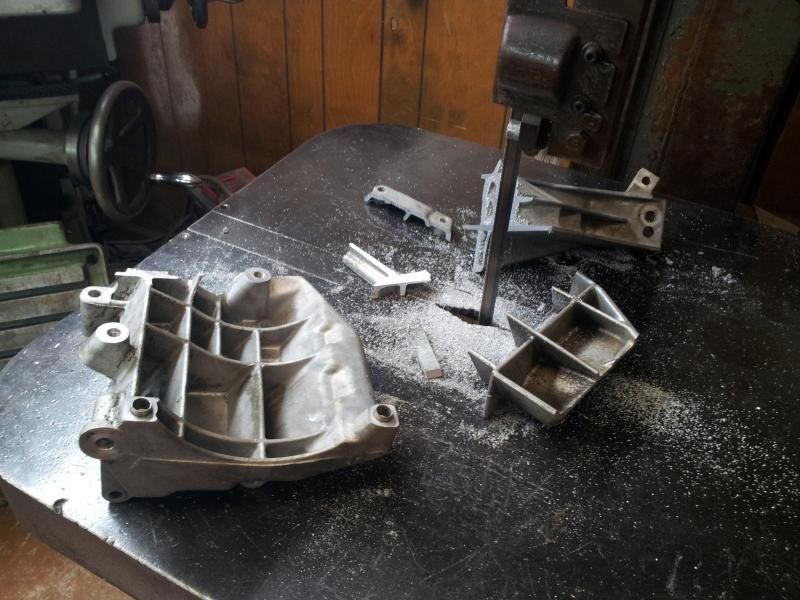
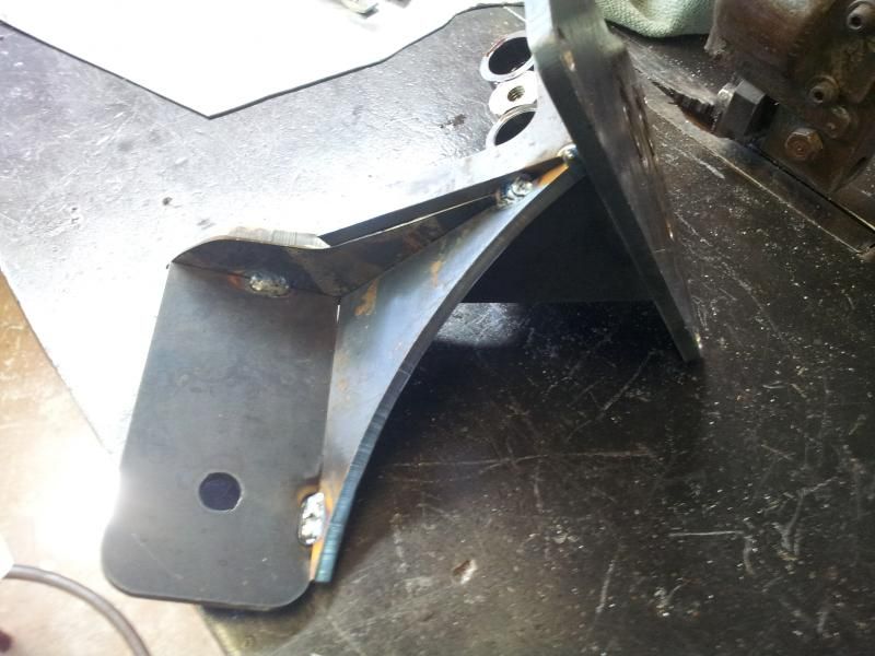
Heres some revised mounts, going to weld them up some time this weekend. And i got my 1940's grob bandsaw to the AC bracket/Engine mount. Now its just a AC bracket
Before its untimely demise, My german made Ruhla(mill) looked on in horror im sure.
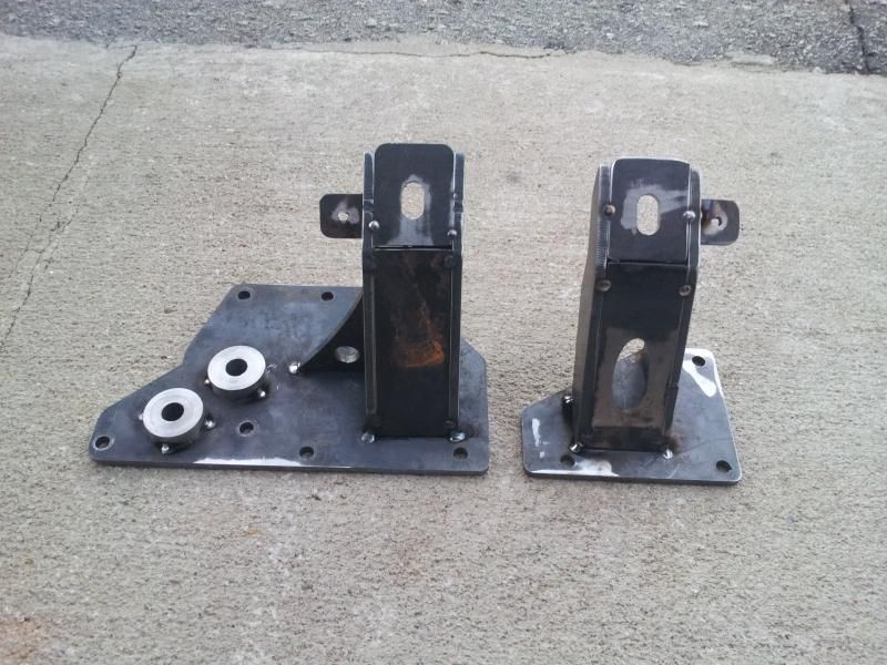
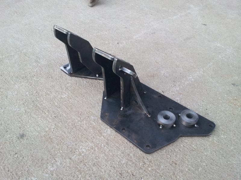
Some finished pictures of the mounts. Whipped out some more bungs. Going to try a simpler approach this time. Ill be working on that some more in my head lol
The torsional stiffness of the structure is related to the radius of gyration of the smallest section, which in this part is right at the "wrist" at the base of the plate that bolts to the rubber mount. Increasing the minimal dimensions of that section should be the priority for bracing.
Although if you eliminated the flat plates altogether and use round tubing instead, that would probably be better, as a cylinder is the stiffest shape going (external dimension = radius of gyration by definition)
I apologize, i was irritated over the mount coming out like it did. And then i felt as if you were just blatantly ignoring what i commented about. More productive posts to come.
You expect people to read that mental masturbation you post on your thread. But you dont have 5 minutes to read my "simple minded" post. I mentioned that that was one of my concerns.
From your wording, it came across that you were concerned about the bolt loading rather than the bracket gusseting.
After all, the stock mount arms load the bolt joints mostly in tension/compression while the one you have load them in shear. I don't think that will be a problem for the joint from the bracket to the block... I was just noting that the bracket itself may need additional gusseting to deal with the load (over time... fatigue due to dynamic loads being much higher than static loads).
You expect people to read that mental masturbation you post on your thread. But you dont have 5 minutes to read my "simple minded" post. I mentioned that that was one of my concerns.
There's going to be a lot of torque on that bracket because of the way the mount pad is offset from the bolt pattern on the engine block... It doesn't look like it's braced well against that torque.
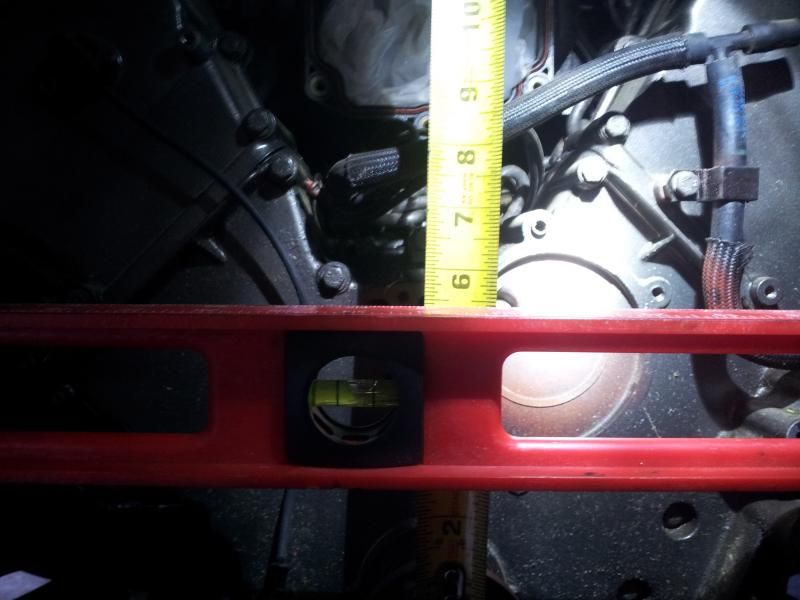
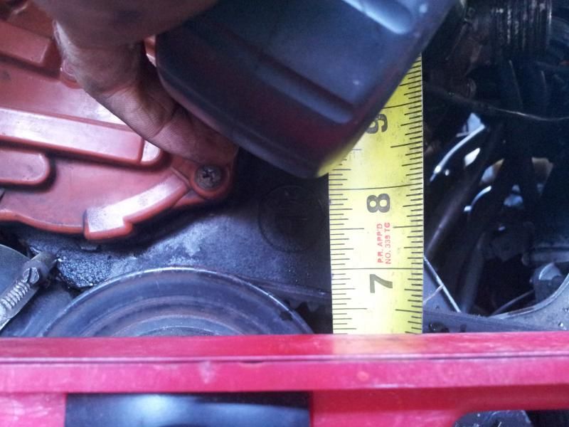
Ok, after some measurements this is what I got. Measuring with a 59.4mm tall level from the top of the frame rail pinch. NOTE: This is after i modified the pan on the M62. There is 1.125'' from bottom of pan to top of subframe. The camera angle is not in line with the reading, so within line of sight i got these measurements
M62: Im measuring 5.5''(13.7cm) from the top of the nut to top of the level
M20: Im measuring 6.375''(16.2cm) from the top of the nut to the top of the level.
So if we do the math, keeping in mind that the nut on the M62 is 28mm and the M20 nut is 22mm.
Center of M62 crank to top of frame rail is 9.16CM (13.7CM-59.4MM(level height)+14mm(center of crank)
Center of M20 crank to top of frame rail is 11.36CM (16.2CM-59.4MM(level height)+11MM (center of crank)
Thanks! Can we make this post a sticky? ;)
Originally posted by JGood
My notched pan is about 5mm from the subframe. So when you bring your engine down ~20mm like I did when I made my mount arms (to replace my 20mm subframe spacers), you'll be almost dead on with the factory m20 alignment.


Leave a comment: