
Just got my external welded in, and it's a night and day difference. The car pulls WAY harder, and gets scary fast.
That being said, the car hit 15 lbs today, and I think ive only got a 11 lb spring in there. maybe an 8. Im running a cheap ebay wastegate. which is un-neccessarily large. Im wondering what would cause the car to boost creep like that. should I get a smaller spring? or replace the wastegate?? I dont want to drop the dime on a tial, but If I have too well then I have too.
That being said, the car hit 15 lbs today, and I think ive only got a 11 lb spring in there. maybe an 8. Im running a cheap ebay wastegate. which is un-neccessarily large. Im wondering what would cause the car to boost creep like that. should I get a smaller spring? or replace the wastegate?? I dont want to drop the dime on a tial, but If I have too well then I have too.
 [/url]
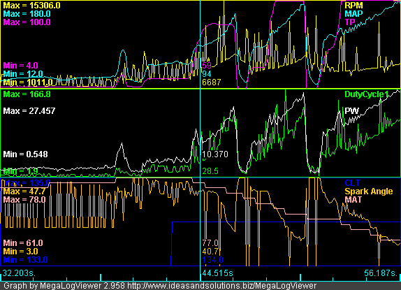

Comment