

bump?
-
updated: fuse 21 was suppose to be 7.5 but the previous owner put in a 10a fuse. i have a bad feeling something is blown instead of the fuse.Comment
-
updated: i replace fuse 21(previous owner put in a 10) to a 7.5 and now everything is working again, just that the speedometer get stuck sometimes and you have to tap on have cluster. so far i been driving it for the whole day and still working.Comment
-
did you check the speed sensor at the differential. the wires may not be connected or change the sensor at the differentialsComment
-
Comment
-
unplug the alarm and see what happens!KingB

Comment
-
Comment
-
oh shit i didnt know there was a 2nd page :yawn:KingB
Comment
-
Other than the fuses, here's something else to check.
When you unplug the connectors from the instrument cluster you have to take care to pull them straight off, not twist them or rock them from side-to-side. If you wiggle them it stresses the pins at either end of the connectors.
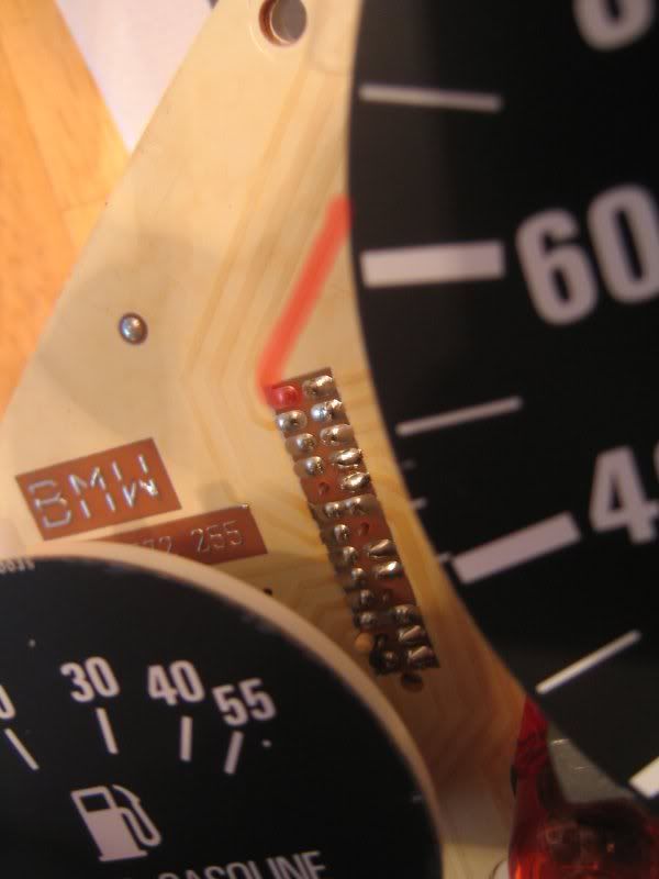
I had an issue with my speedo and OBC intermittently cutting out. Power comes to the speedometer from Fuse-12 to Pin-13 on the 26-pin C2 connector (the White connector on back of the instrument cluster). Pin-13 is the topmost-left pin marked in red here:
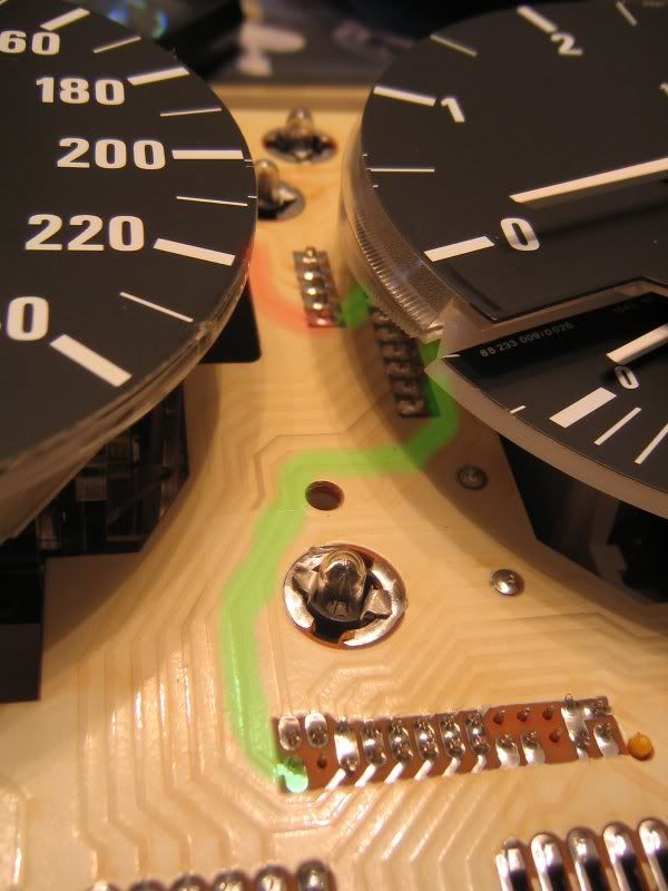
Follow that trace along the circuit board to the bottom-most pin of the connector into which the speedometer is plugged. Power is fed to the speedo through that pin, then continues along the green trace to Pin-13 on the 26-pin C3 connector (the Yellow connector on back of the instrument cluster), and from there out to the OBC.
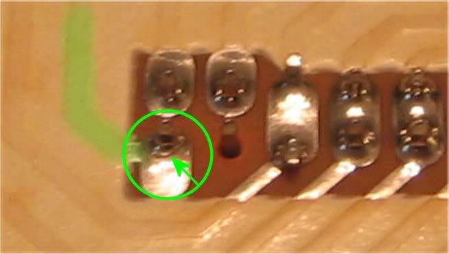
Below is an (unfortunately blurry) closeup of what this pin looked like. Note the green arrow points to where the solder joint is cracked. That pin was loose and could be wiggled back and forth, a direct result of too much force being used to remove the Yellow 26-pin C3 connector.
You can't see it in the photos, but when I had a closer look at the pin in the topmost photo, at the start of the red trace, its solder joint had a hairline crack as well.
The solution is to use a soldering gun to reflow the solder joints to ensure a good connection. Thereafter treat the connectors with care when unplugging them.
I don't know for sure whether this is the cause of your issues, but it's worth taking a look.Comment


Comment