

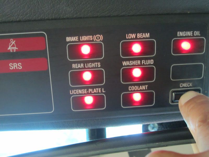
I've had a really annoying issue with my tail lights for over a year now. The overhead check panel randomly comes up with a warning telling me that one of my tail lights is burned out, except it's not. There doesn't seem to be any reason for it. The tail lights are working fine.
It's not even like going over a bump sets it off. I can be sitting idling at a stop and suddenly the check light comes on in my instrument cluster and the overhead check panel shows a "REAR LIGHTS" warning. It doesn't do it every day. Sometimes a whole week goes by and I think it's cured itself, but then it starts doing it again. Grrrrrrrr.
I've tried replacing the tail light bulbs, no difference. I've taken the tail light clusters all apart, cleaned up all the contacts, no difference. I even uninstalled and opened up the check relay box (mounted under the radio antenna). There's nothing wrong with it. It works perfectly.
I studied the wiring diagram. Power to either tail light bulb flows through the check relay closing two relay switches (one for each tail light bulb). As long as both tail light bulbs are receiving power and the filaments provide a path to ground, then both relay switches remain closed. When either or both bulbs burn out, then one or both of those relay switches open interrupting the ground path from the fault indicator, which triggers the warning light in the overhead check panel.

Studying that diagram again yesterday I finally had a clue! That ground connection to the fault indicator on the overhead check panel is via Pin-13 of the 26-pin connector (two rows of 13 pins). That means it's one of the outermost corner pins. If those large connectors aren't pushed on or pulled off straight, it's the end pins that see the highest bending stresses. Gee, I wonder...
So, it was time to have a closer look at the check panel itself.
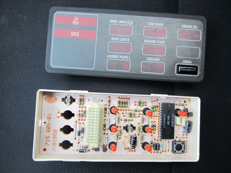
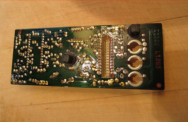
With the box opened up, the circuit board can be lifted out. Flipped over, it looks like this. Pin-13 is at the bottom-left corner of the socket for the 26-pin connector visible here.
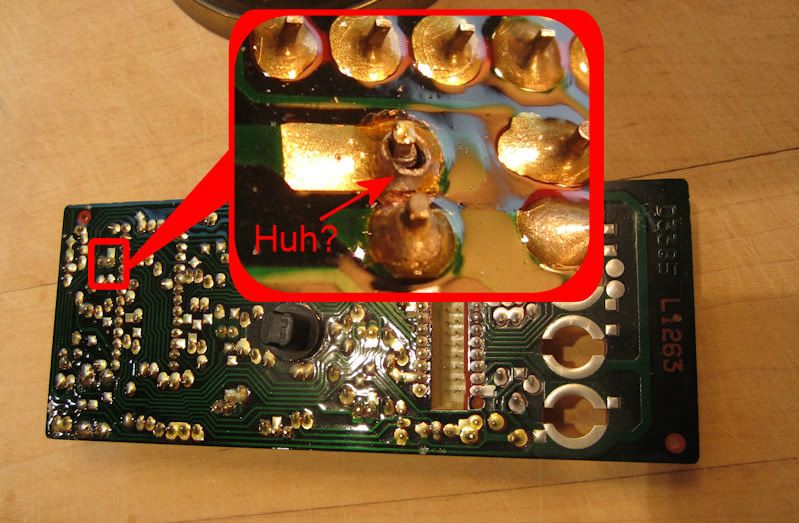
Check it out! There's the problem right there. The solder joint has a hairline crack around that pin.
Eureka!!! Whipped out the soldering-iron, reflowed that solder joint, and hallelujiah, I think it's fixed now!
The warning light hasn't come on again since then. Of course this might just be one of those weeks where it has mysteriously and temporarily fixed itself...

It's not even like going over a bump sets it off. I can be sitting idling at a stop and suddenly the check light comes on in my instrument cluster and the overhead check panel shows a "REAR LIGHTS" warning. It doesn't do it every day. Sometimes a whole week goes by and I think it's cured itself, but then it starts doing it again. Grrrrrrrr.
I've tried replacing the tail light bulbs, no difference. I've taken the tail light clusters all apart, cleaned up all the contacts, no difference. I even uninstalled and opened up the check relay box (mounted under the radio antenna). There's nothing wrong with it. It works perfectly.
I studied the wiring diagram. Power to either tail light bulb flows through the check relay closing two relay switches (one for each tail light bulb). As long as both tail light bulbs are receiving power and the filaments provide a path to ground, then both relay switches remain closed. When either or both bulbs burn out, then one or both of those relay switches open interrupting the ground path from the fault indicator, which triggers the warning light in the overhead check panel.
Studying that diagram again yesterday I finally had a clue! That ground connection to the fault indicator on the overhead check panel is via Pin-13 of the 26-pin connector (two rows of 13 pins). That means it's one of the outermost corner pins. If those large connectors aren't pushed on or pulled off straight, it's the end pins that see the highest bending stresses. Gee, I wonder...
So, it was time to have a closer look at the check panel itself.
With the box opened up, the circuit board can be lifted out. Flipped over, it looks like this. Pin-13 is at the bottom-left corner of the socket for the 26-pin connector visible here.
Check it out! There's the problem right there. The solder joint has a hairline crack around that pin.
Eureka!!! Whipped out the soldering-iron, reflowed that solder joint, and hallelujiah, I think it's fixed now!
The warning light hasn't come on again since then. Of course this might just be one of those weeks where it has mysteriously and temporarily fixed itself...
Comment