
I am a senior in a ME program and we have a capstone project that we must complete to graduate the program. The only courses I need to complete are a a mechanical design course and a FEA course; both of which I am taking right now. Upon completion of this project in June, I will be graduating and hopefully finding a job.
I wanted to do something with my e30, and I am specifically interested in suspension analysis and design. Originally I was planning on making tubular control arms, but my professor seemed to think that it was a high risk project (and I don't blame him... I would rather be riding in a car with critical parts designed be an engineer with more experience, rather than an engineering student.
I started off by making a project proposal. The proposal included my function statement, design requirements, success criteria, testing methods, analysis, models etc. All of the drawings are to be ANSI-Y 14.5 compliant (still need to do tolerances and geo. tolerancing on some of them.)
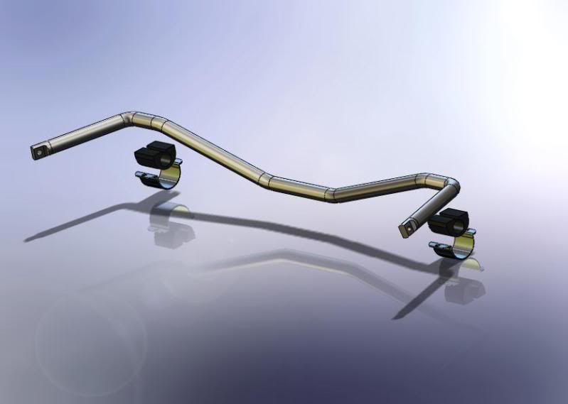
Here is a shot of the assembly (minus the rod ends). The bushings and brackets are not a good representation of the actual parts, I just put them in there quickly for reference.
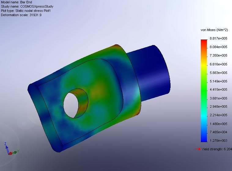
Here is a screen capture of me playing around with Cosmos Express in Solid Works. I am just taking the FEA course, and we are going over the linear algebra right now. I just need to spend some time learning how to properly load and constrain it.
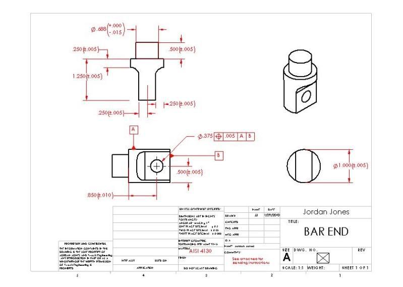
Here is that bar end. Since making the model, I have slightly changed my design, so this part is not shown how it will be made. Also, it needs to be dimensioned properly.
I don't have screen shots of the excel sheets I have. My analysis was done once on paper and then put in Excel to do iterations for each potential size. I have data for motion ratio, an assumed load, bar dimensions, weight per unit length, cost per unit length etc. and calculations for percent decrease in bending stress, percent decrease in angle of twist, percent increase in bar rate, and an approximate percent decrease in roll angle when installed. I need to find some center of gravity data for the e30, or find some corner scales to use.
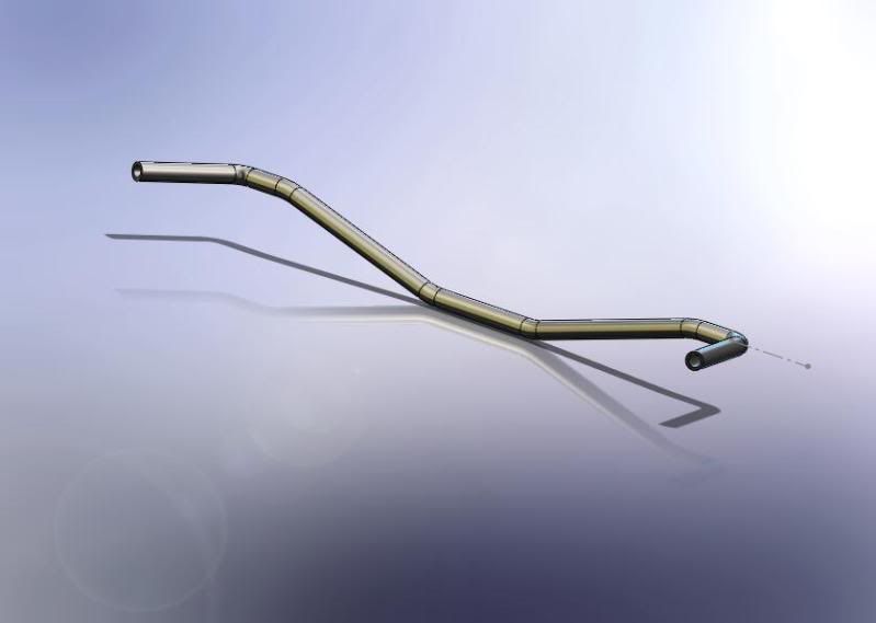
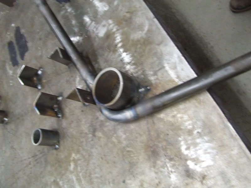
I came up with 4130 1" OD, .760 ID round tube. Since the radii on a couple of the bends are pretty tight (~1.25 in), pretty much everyone that has a mandrel bender will not have a die small enough. I talked to some manufacturers with CNC benders, and I decided that I was better off trying to bend it myself. I thought that I could get it to bend nicely. So I packed sand in to the bar, and tack welded .750 bar stock to it that had been put in to the ends of the bar 6" on each end. I don't have a very good picture illustrating that, but I believe you can see it in one of the pictures below. To do this I (with the help of a couple friends) set about making a jig. We have a welding table that would be perfect, so we went at it.
We chose to use the "concave" (or top I guess) edge as reference. I found the center of the factory bar, marked it, marked the table and used the center of the tube to be bent as a reference on all three jigs.
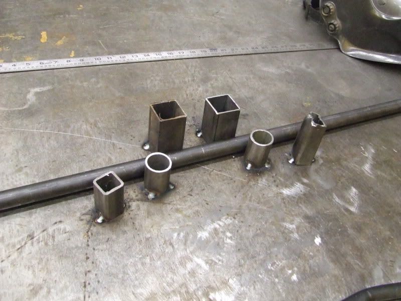
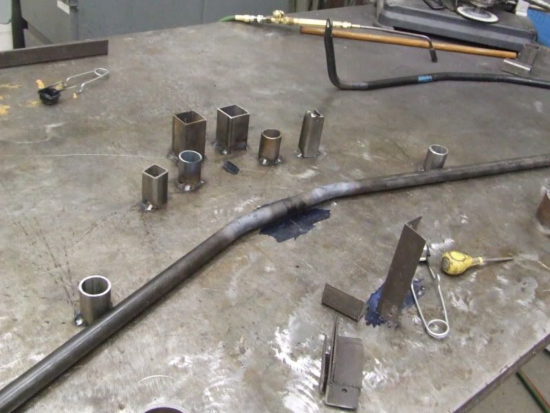
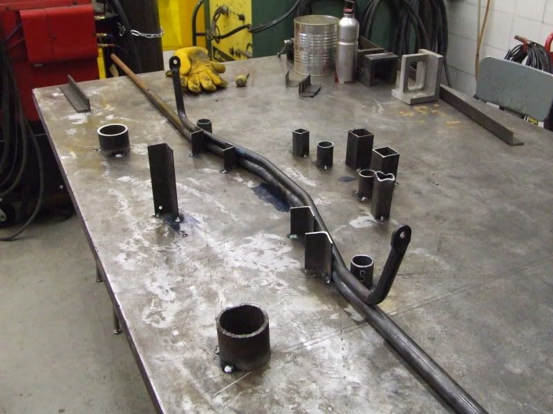
Here is the first jig being made. The factory bar was laid on the table, proper radius "dies" were placed at the bends and welded to the table. The square tube was left loose until the new bar was put in due to the larger diameter.
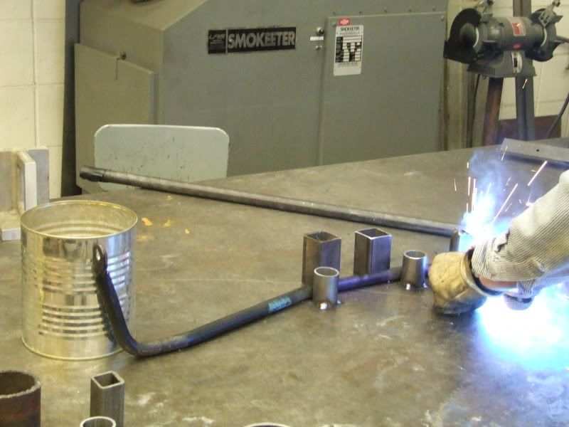
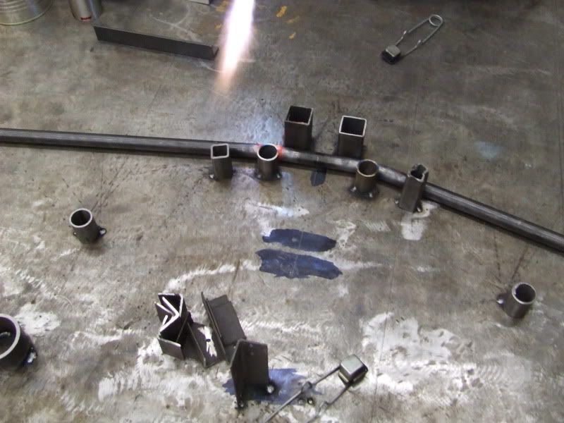
Here is the first jig before bending. The smaller square tube was welded there just as a reference. A line was scribed on the table to reference during bending. The reason you can't have stops right at the edge that you want to bend to is because when you heat it up you greatly lower the yield strength. Even at these temps, the steel still has tensile strength, so you must bend it past the point where you want it to be static.
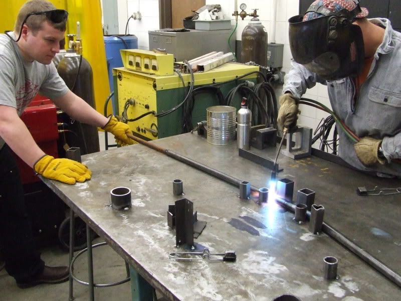
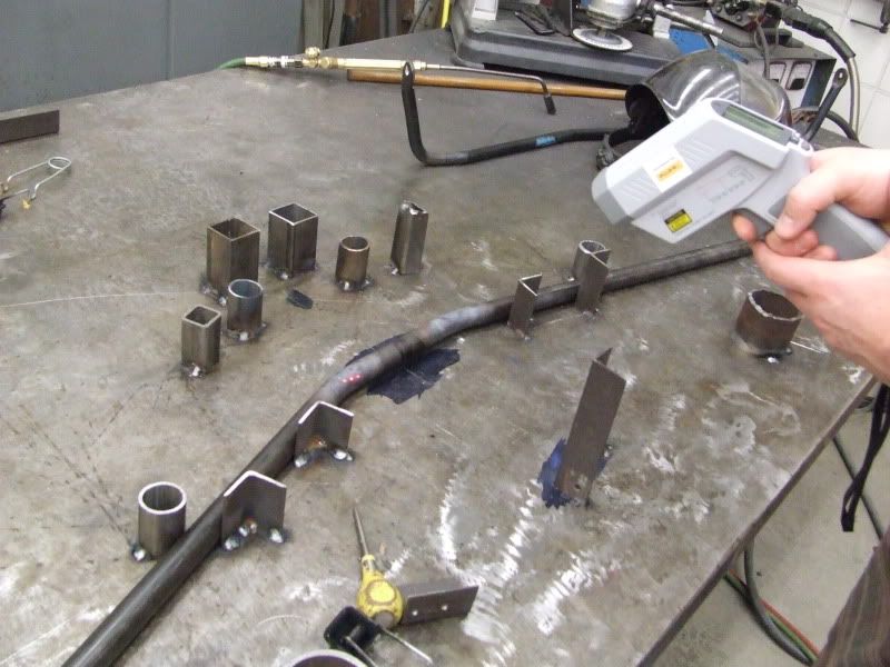
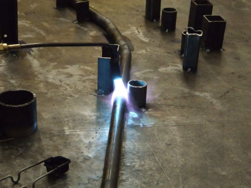
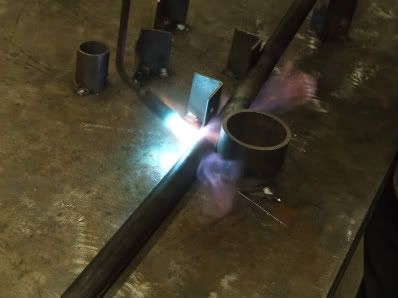
Then my friend Matt grabbed the oxy-acetylene torch and heated it up. Once it was up to temp (we were taking readings with an infrared thermometer) I was able to pull with relatively low force.
I don't want to ramble too much, so I will just show pictures of the process.
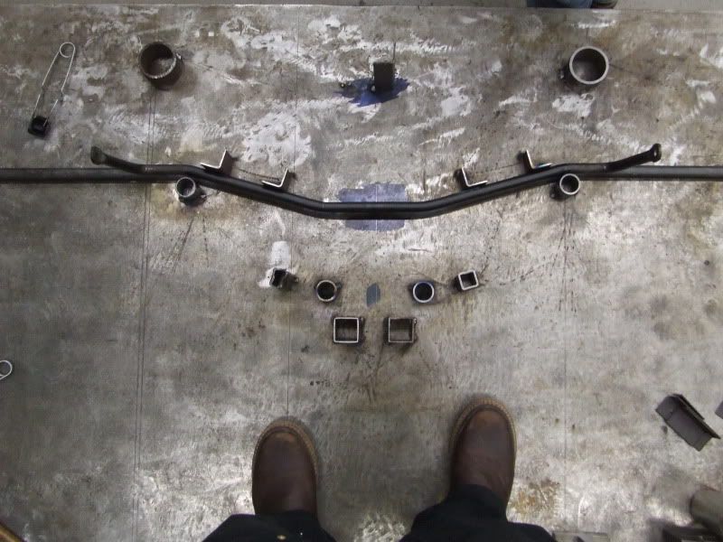
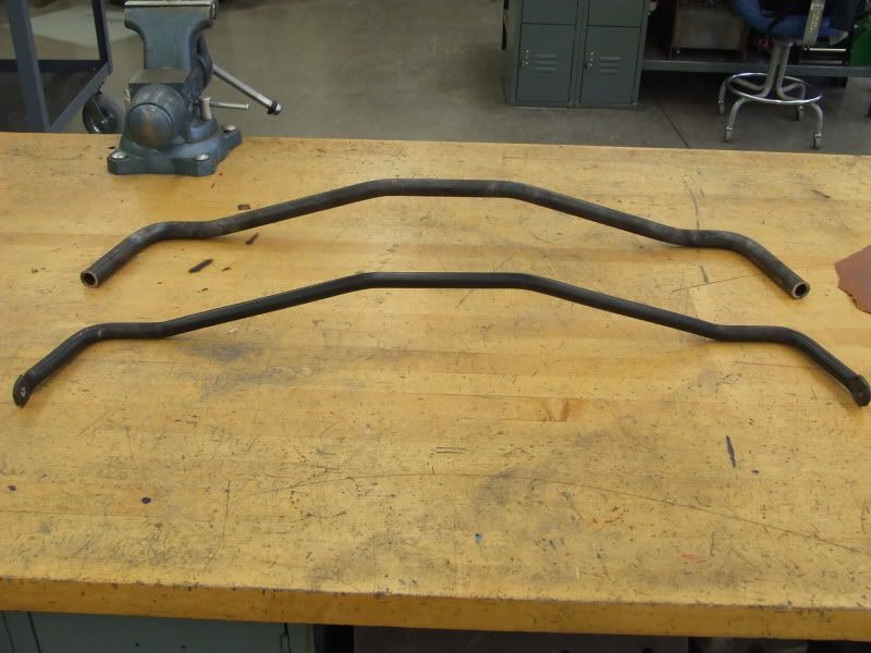
That was yesterday. I had extra material, so I decided that while the jig was there, I might as well make another one. I did that today, and I've now got two sway bars. I don't know what I'll do with it. The repeatability of that process is actually quite good. The ends of the bars are just rough cut for right now. I am now working on designing a better bar end, and I will make those next week.
I've also got a time temperature transformation for 4130, as well as some empirical data from Lincoln. It turns out that at the temps we were bending, air-quenching the material maintains it's material properties. That's the beauty of these alloys I guess. However, the bar ends will be welded on to the bars and in that situation we will have to use a torch to reheat the weld and surrounding material to about 1500 F and let it cool. This will relieve the stress concentration that the molten material causes.
I wanted to do something with my e30, and I am specifically interested in suspension analysis and design. Originally I was planning on making tubular control arms, but my professor seemed to think that it was a high risk project (and I don't blame him... I would rather be riding in a car with critical parts designed be an engineer with more experience, rather than an engineering student.
I started off by making a project proposal. The proposal included my function statement, design requirements, success criteria, testing methods, analysis, models etc. All of the drawings are to be ANSI-Y 14.5 compliant (still need to do tolerances and geo. tolerancing on some of them.)
Here is a shot of the assembly (minus the rod ends). The bushings and brackets are not a good representation of the actual parts, I just put them in there quickly for reference.
Here is a screen capture of me playing around with Cosmos Express in Solid Works. I am just taking the FEA course, and we are going over the linear algebra right now. I just need to spend some time learning how to properly load and constrain it.
Here is that bar end. Since making the model, I have slightly changed my design, so this part is not shown how it will be made. Also, it needs to be dimensioned properly.
I don't have screen shots of the excel sheets I have. My analysis was done once on paper and then put in Excel to do iterations for each potential size. I have data for motion ratio, an assumed load, bar dimensions, weight per unit length, cost per unit length etc. and calculations for percent decrease in bending stress, percent decrease in angle of twist, percent increase in bar rate, and an approximate percent decrease in roll angle when installed. I need to find some center of gravity data for the e30, or find some corner scales to use.
I came up with 4130 1" OD, .760 ID round tube. Since the radii on a couple of the bends are pretty tight (~1.25 in), pretty much everyone that has a mandrel bender will not have a die small enough. I talked to some manufacturers with CNC benders, and I decided that I was better off trying to bend it myself. I thought that I could get it to bend nicely. So I packed sand in to the bar, and tack welded .750 bar stock to it that had been put in to the ends of the bar 6" on each end. I don't have a very good picture illustrating that, but I believe you can see it in one of the pictures below. To do this I (with the help of a couple friends) set about making a jig. We have a welding table that would be perfect, so we went at it.
We chose to use the "concave" (or top I guess) edge as reference. I found the center of the factory bar, marked it, marked the table and used the center of the tube to be bent as a reference on all three jigs.
Here is the first jig being made. The factory bar was laid on the table, proper radius "dies" were placed at the bends and welded to the table. The square tube was left loose until the new bar was put in due to the larger diameter.
Here is the first jig before bending. The smaller square tube was welded there just as a reference. A line was scribed on the table to reference during bending. The reason you can't have stops right at the edge that you want to bend to is because when you heat it up you greatly lower the yield strength. Even at these temps, the steel still has tensile strength, so you must bend it past the point where you want it to be static.
Then my friend Matt grabbed the oxy-acetylene torch and heated it up. Once it was up to temp (we were taking readings with an infrared thermometer) I was able to pull with relatively low force.
I don't want to ramble too much, so I will just show pictures of the process.
That was yesterday. I had extra material, so I decided that while the jig was there, I might as well make another one. I did that today, and I've now got two sway bars. I don't know what I'll do with it. The repeatability of that process is actually quite good. The ends of the bars are just rough cut for right now. I am now working on designing a better bar end, and I will make those next week.
I've also got a time temperature transformation for 4130, as well as some empirical data from Lincoln. It turns out that at the temps we were bending, air-quenching the material maintains it's material properties. That's the beauty of these alloys I guess. However, the bar ends will be welded on to the bars and in that situation we will have to use a torch to reheat the weld and surrounding material to about 1500 F and let it cool. This will relieve the stress concentration that the molten material causes.

 [/url]

Comment