
Great work.
-

-
I see, interesting. I figure even with that, it would still have some give, but it took a torch to bend it, so perhaps it won't flex enough while on the car to not return to it's original shape on it's own. I'm excited to hear how well this works out, it really makes me want to start making my own sway bars.
Comment
-
I like this thread a lot. Keep the pictures coming.
And to the guy who asked if stock E30 sway bars are hollow: no.paint sucksComment
-
Just a thought for "production" purposes you could crimp the ends of the tube together and drill a hole instead of manufacturing the insert and welding it in. Would save on heat treatment too. Are you putting safety washers on you rod ends? Usually a standard practice with single shear rod ends for misalignment purposes. Cool project, I hope your job opportunity works out.Comment
-
Stamping the ends is exactly what I was planning on doing. That is the way the factory mounting points are made and it seems that it will cut down production time and cost significantly. The rod ends will have washers where they connect to the bar. The end that connects to the control arm will be under double shear, and will have spacers for alignment purposes.
Comment
-
Well I am still waiting for my first bar to come back from PC. I've taken the other bar that I bent and make a different mounting method. Unfortunately I am a space case and left my camera at home when I did it. I simply put the ends of the bar in a hydraulic press to be pinched. Then I bent the pinched portion to the appropriate angle (on the factory bar the plane that the mounting points are on is offset 16 degrees relative to the lever arm of the bar. I put the holes in it and it is sitting at the lab. It is not as attractive as the other bar, but it is just as functional, much faster and less expensive to produce.
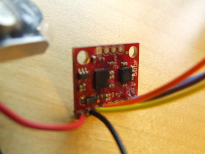
Anyways, I have turned my focus towards the instrumentation and data collection part of my project. My design requirements specify that the new sway bar must decrease roll angle by a certain amount (I think I spec'd 20% min. decrease). So I must have a way to measure the angle of the car during cornering relative to the angle at rest. I looked around and found a little circuit board that has a three axis accelerometer and a two axis gyroscope on it. Here it is: http://www.sparkfun.com/commerce/pro...oducts_id=9268.
Turns out that the instrumentation and testing part of this project will be the most expensive too. I also had to buy a little voltage regulator. The board needs to have a relatively consistent 3.3V DC for it to work properly. It will plug in to the cigarette lighter in the car for power and that 12-14V needs to be regulated.
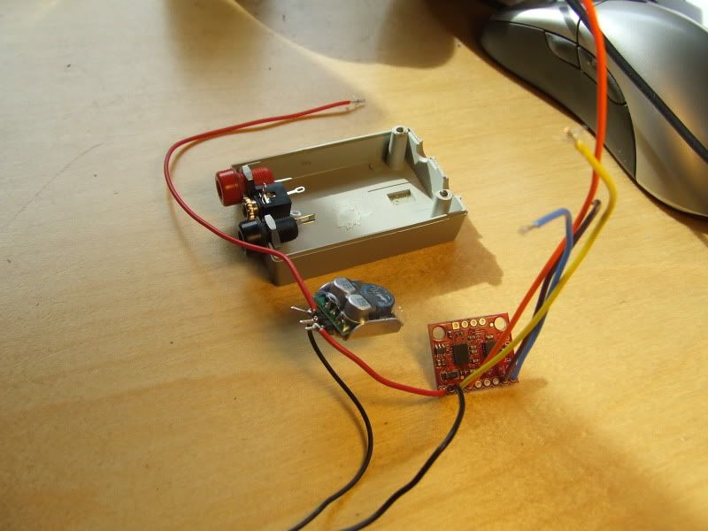
I just got the board and regulator and I wanted to hook them and see if it was working. I had to solder some leads on to the board to hook up the power supply and oscilloscope.
You can see the board and the regulator here. This particular board has outputs for three axes of the accelerometer, two for the two axes of the gyroscope and two for a 4.5x amplified signal for the two axes of the gyro. I've got leads on there for two axes from the accelerometer and two from the gyro. I will only use one output from the gyro and one from the accelerometer.
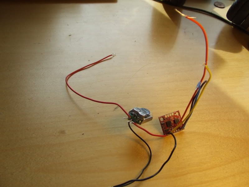
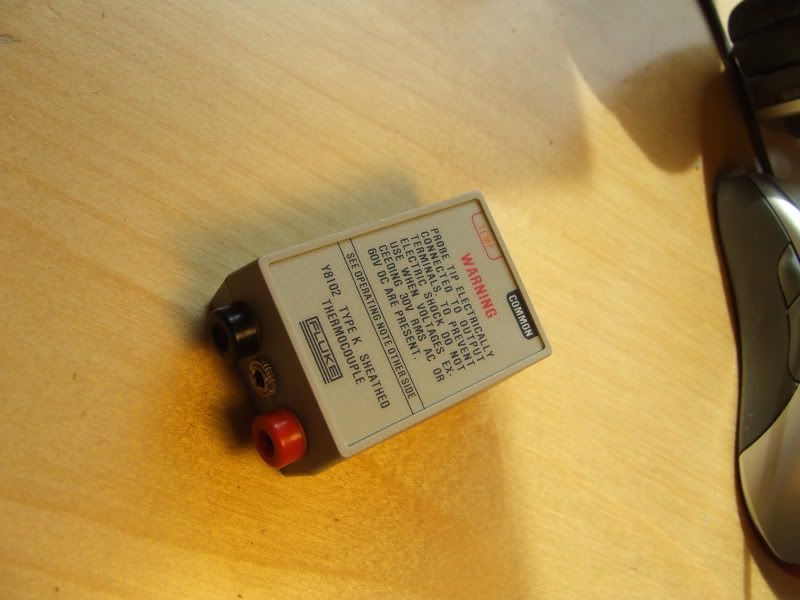
I'm also taking a case that was used for a thermocouple to mount this stuff. It will have one plug for power from the cigarette lighter, and two plugs for the gyro output and two for the accelerometer. It should all be packaged pretty nicely when done.
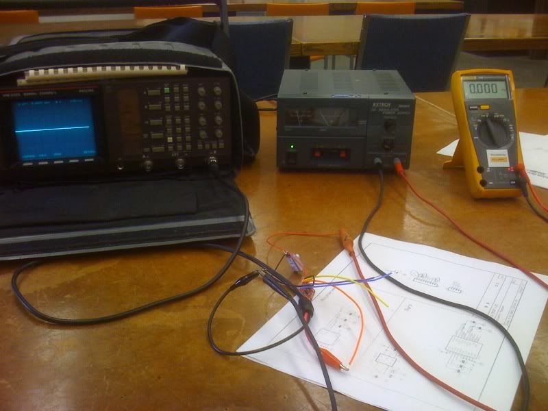
The outputs from the sensors will go to a digital oscilloscope that is interfaced with a laptop. This will log my data and I will be able to put it in Excel and do cool stuff with it.
Here it is hooked up to the power supply and scope
And it works! This wave form is a result of me holding the board and rotating it back and forth.
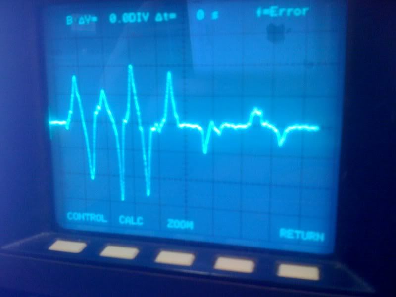
So the gyro will give me an angular rate vs. time plot. I will integrate this plot (or just sum the area under the curve with respect to time) to get an angle. This test will be done with no sway bar, the factory one and probably both of the ones I have made.
Comment
-
So it is being made from hollow tubing? I still think is going to yield long before you think it is.
Check Us out on Facebook
Needing a harness adapter or wiring help? Check it out: also have 24v motor mounts, E30 M3 covers and E36 ECU mounts!
Full Product Line Tuning
OBD2 Tuning Available! OBD2 E36, S54 Swap, S62 Swap, etc: tuning@MarkertMotorWorks.com Dyno ThreadComment
-
Nice work, awesome project.
The testing part of the project is always the most fun :D
Looks like tons of fun, and you get a sweet part once you're done.Comment
-
I've checked bending and torsion.
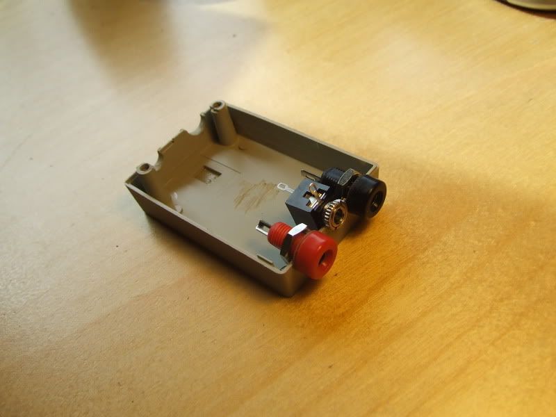
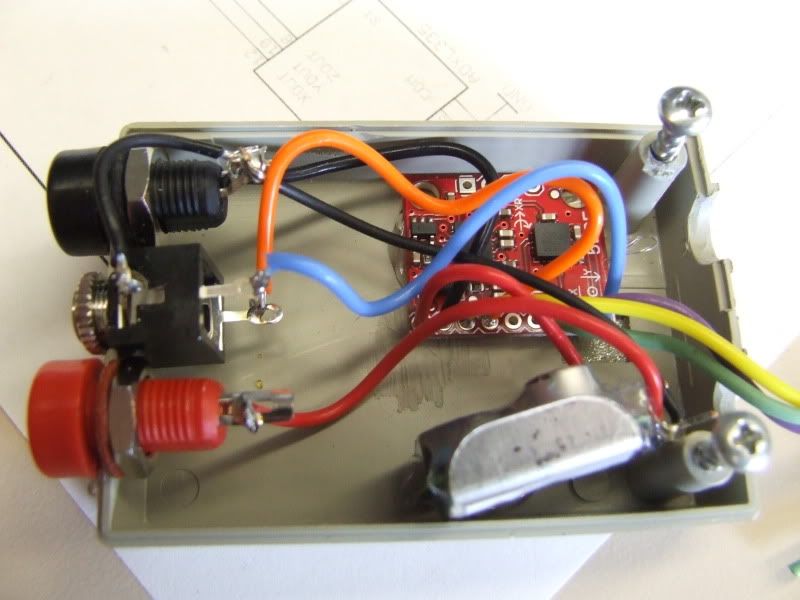
Here is a picture of what I did earlier. Got the board and the regulator in the case and soldered. The banana plugs are for power from the cigarette lighter and the tip/ring/sleeve is for the signal wires that go to the scope.
Comment
-
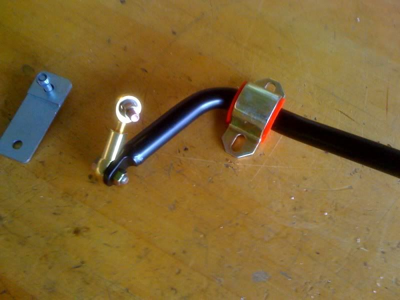
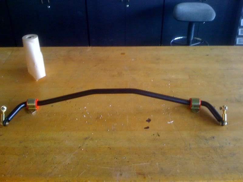
I finally got the bar back from powder coat. It took way too long. I've got the links and the bushings/carriers, and I just need to prep the subframe and weld the reinforcements on. The ends will need to be spaced slightly from the bar to keep the range of motion of the spherical bearings.
Comment
-
Not much progress to report. The bar is on the car, and I can definitely feel a difference. I will be doing the testing this week and will have some actual data to report back with.
I have recently made a little website to chronicle my project. It's a blog format just because I am new to this shit and wordpress is free and easy to use.
Check out www.twoJsEngineering.com
Comment
-
Nice job! Keep up the good work1990 Alpinweiss 325i - secret 500whp buildOriginally posted by audiquattrot
2000 Audi S4 B5 Laser Red
1990 Nissan 240sx - Drift Missile
2006 CBR600RR

Comment
-
Thank you.
I am finally all prepared to do the in-car testing. I've got the circuit all built and tested. I am using this Fluke scope/meter that is property of my school:
.jpg)
This thing is worth more than 99% of the e30's on this board, including mine.
Here is a shot of when I was testing the sensors and trying to eliminate the noise in the circuit. Before having access to the Fluke data logger, I was considering using some $200 piece of shit digital osciloscope. I was using the old school scope in the picture to test consistency between the two. I have since abandoned that.
.jpg)
In the car I will not need that power supply either as my sensors will be powered by the 12V at the cigarette lighter and the data logger and laptop are battery powered.
If weather permits, testing will be done tomorrow.
Comment


 . The aluminum alloy's we analyze at work for aerospace usage have a typical 60-70 ksi yield strength. 135 is a more typical Fty for alloy steel. What failure modes have you checked?
Comment