Announcement

Collapse
No announcement yet.

ttrousdell's Project Thread (E30 M3 & S38 swap content)

Collapse
X
 
  • Filter
  • Time
  • Show
Clear All
new posts

    I was able to get a few more things done in the last two days. Coolant manifold, t-stat assembly, distributor and wires, fuel rail and injectors.

    Click image for larger version

Name:	DSC01035.jpg
Views:	1
Size:	118.0 KB
ID:	7155621

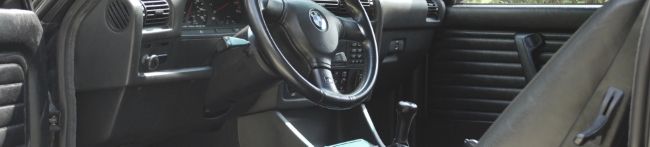
    The custom radiator has really helped out tremendously with allowing me to get all of this to fit. The thermostat housing fits with just enough clearance.

    Click image for larger version

Name:	DSC01037.jpg
Views:	1
Size:	88.0 KB
ID:	7155622

    Its pretty obvious that the shop that performed this swap had very little pride in what they were building. Ive have seen so much hastily put together shit on this engine. There is no way that i can use those shitty hoses so i will have to source some.

    Click image for larger version

Name:	DSC01061.JPG
Views:	1
Size:	92.7 KB
ID:	7155623

    Basic diagram made of the coolant system. Not sure if im going to install the expansion tank on the passenger side yet. If I do i wont have to run some lines across the bay. I will not be using a heater core. It looks like in the original setup water came out of the exit of the water pump, labeled B, through the heater and into the back of the engine labeled A. Can I just block them or should I run a hose connecting them? From what I could see blocking them would be fine.

    Click image for larger version

Name:	cooling system s38.png
Views:	1
Size:	19.2 KB
ID:	7155624

    The Build:
    http://www.r3vlimited.com/board/showthread.php?t=191125

    Comment


      Looking good!

      Comment


        After loking at the harness it became aparent that this also had been molested in an attempt to get it to fit better or simplify it. I dont find it that good that I can feel crimp connectors below the electrical tape.

        Click image for larger version

Name:	DSC01050.jpg
Views:	1
Size:	69.7 KB
ID:	7155625

        So now i'd like to know what every connector on this harness if for, whats not needed, what is not original, etc...

        Click image for larger version

Name:	DSC01058.jpg
Views:	1
Size:	80.3 KB
ID:	7155626
        1. DME Connector
        2. ?
        3. random white wire that we figured out grounded the fuel pump relay
        4. 2 fat red wires. power
        5. O2, Main, and fuel pump relays
        6. Plenum control computer
        7. 2 wires for ignition coil, 2 black wires are ground
        8. ?
        9. Alternator main power
        10. Alternator exciter
        11. Oil level Sensor
        12. Starter
        13. Starter
        14. O2 sensor
        15. Starter
        16. X20 25Pin connector
        17. Diagnostic Port
        18. Hot Wire MAF
        19. Air Temp
        20. Manifold Air Pump thing
        21. Charcoal canister purge valve
        22. Oil Press
        23. Oil Temp
        24. Manifold Air pump thing
        25. TPS
        26. Exhaust pump system
        27. No #27 because I can't count
        28. Tach pulse sensor
        29. CPS
        30. Coolant
        31. Coolant
        32. IVC
        33. Injectors
        Last edited by ttrousdell; 11-22-2013, 08:20 PM.

        The Build:
        http://www.r3vlimited.com/board/showthread.php?t=191125

        Comment


          Nice motor going E30 :)
          https://www.facebook.com/Cry_77_IX-110483784967661
          https://www.instagram.com/cry_77_ix/

          Comment


            nice projekt:up:
            I think that I need to copy a few things

            how thick that radiator is?
            how yours orginal hood lock, it still works?
            e30_cabrio_336[/URL]

            Comment


              2. ABS or cruise control, can't see the connector clearly enough
              3. possibly oil temp signal to cluster or aux gauge
              4. yes, ground if it is a single thick wire
              6. plenum actuator
              7. yes, ignition coil
              8. possibly e-box fan, hard to see the connector
              14. yes, o2
              21. yes, charcoal
              26. doesn't matter, you don't connect it to anything.

              If you block off the driver side of the the system, how will you loop the back of the cylinder header outlet into the system? That aside, without the core in play you'd have a significantly less efficient system without the ability to use the heater core to release heat, you'd have no cabin heat or a way to instantly help bring down engine temp and it is also more difficult to know when your system is bled.

              Comment


                damn this looks great!

                I wish I had time to come out Saturday for the install.I had a wake, then had to pick up last minute things for my race on Sunday, did the Zombie Race.
                Click here to leave me feedback on our transactions. :p

                Comment


                  Originally posted by ttrousdell View Post
                  [ATTACH]70712[/ATTACH]

                  Basic diagram made of the coolant system. Not sure if im going to install the expansion tank on the passenger side yet. If I do i wont have to run some lines across the bay. I will not be using a heater core. It looks like in the original setup water came out of the exit of the water pump, labeled B, through the heater and into the back of the engine labeled A. Can I just block them or should I run a hose connecting them? From what I could see blocking them would be fine.

                  [ATTACH]70713[/ATTACH]
                  Because the thermostat is appears to be a recirculating design, you probably won't have any problems with extended warm-up time by removing the heater core circulation.

                  However, I don't think running without a heater or core is a good idea in a street car. You won't be able to defog your windshield, for example.
                  A couple of years ago, the heater core in my '92 E34 sprung a leak, so I looped the lines temporarily until I could tear the dash apart to replace it. I had to go on a 4 hour drive at night in early April to my new drill location in southern PA. Thank goodness for heated seats. That drive sucked, but would have been hypothermic without the seat heaters.

                  Limiting yourself to only being able to drive the car on bright sunny days with low humiditiy is... well... limiting.

                  Comment


                    It Lives!!!!


                    The Build:
                    http://www.r3vlimited.com/board/showthread.php?t=191125

                    Comment


                      Originally posted by ttrousdell View Post
                      It Lives!!!!


                      Hot Damn !
                      Lorin


                      Originally posted by slammin.e28
                      The M30 is God's engine.

                      Comment


                        Took you long enough Tom...not as long as Dana.
                        ~ Puch Cafe. ~ Do business? feedback ~ Check out my leather company ~

                        Instagram: @BWeissLeather

                        Current cars:
                        ~ '87 325 M30B35 swap
                        ~ '87 535
                        ~ 01 540 Msport 6spd
                        ~ '06 X5 4.8is

                        Comment


                          Wow I can't wait to see some more vids those itb's are so sexy
                          1989 BMW 325is Lachsilber metallic 5 speed
                          2007 BMW 335i KARMESINROT 6 Speed manual
                          2011 BMW X5 35I

                          Comment


                            Make sure you only run it the minimum amount of time necessary to make sure your cooling, oil and electrical systems work before you take it out for a hard break-in


                            I've also corresponded with a GM engineer about break in procedures. He said that the hardest break in is the best. During dyno development of the Northstar, they'd put brand new engines on the dyno. The first thing these engines would see would be 250 degree coolant temps and 300 degree oil temps. They'd run wide open for dozens to hundreds of hours and look beautiful inside.

                            The hard break-in is definitely the best way to go.

                            Comment


                              Originally posted by tonton View Post
                              nice projekt:up:
                              I think that I need to copy a few things
                              how thick that radiator is?
                              how yours orginal hood lock, it still works?
                              Thank you. The radiator is 22.5"x12.5"x3". These demesions fit well. You may be able to get away with making the one end 13.5". There was no way to fit the radiator and the hood lock so it was cut out and added to the scrap pile. I will have to run hood pins.

                              Originally posted by fronton View Post
                              If you block off the driver side of the the system, how will you loop the back of the cylinder header outlet into the system? That aside, without the core in play you'd have a significantly less efficient system without the ability to use the heater core to release heat, you'd have no cabin heat or a way to instantly help bring down engine temp and it is also more difficult to know when your system is bled.
                              The heater core has already been removed from the car. I dont intend to ever make this car a daily again so the inconveiniece of no heat or defogging will not be an issue. I decided to plug both the holes, one in the back of the head and the other at the outlet of the water pump. Yes i will lose the ablity of the heater core to help with cooling the engine but that is not its main function anyway. My radiator and fan should have the ablity to remove enough heat from the system without relying on the heater core. Maybe it might be harder to bleed. Ive never tried to bleed a car without one.

                              Originally posted by F34R View Post
                              Took you long enough Tom...not as long as Dana.
                              Hahaha always a dick but in my defense I was waiting for parts for over a week.

                              Originally posted by The Dark Side of Will View Post
                              The hard break-in is definitely the best way to go.
                              Thanks will. I was wondering what process I should follow for the break in. Ill give this a try. Going to run a 10-30W oil for the break in.

                              Plug for outlet of water pump. Similar one was used for the outlet in the back of the head.

                              Click image for larger version

Name:	DSC01102.jpg
Views:	1
Size:	55.6 KB
ID:	7156378

                              So I don't have to run lines across the engine, Im planning on using this eta exp. tank on the passenger side of the car.

                              Click image for larger version

Name:	DSC01118.jpg
Views:	1
Size:	34.1 KB
ID:	7156379

                              Under plenum mess. Using all new vacuum lines since the others were completely dry rotted.

                              Click image for larger version

Name:	DSC01103.jpg
Views:	1
Size:	81.4 KB
ID:	7156380
                              Last edited by ttrousdell; 05-31-2013, 07:02 PM.

                              The Build:
                              http://www.r3vlimited.com/board/showthread.php?t=191125

                              Comment


                                Unlike the M30B35 swap where I was simply able to use the M20B25 harness, this swap forced me to use the S38 harness and consequently repin the C101/X20 connector. It also didnt help the the harness was messed with so certain things had to be figured out that otherwise woulnt have been an issue. The diagram below is what I used to distinguish the pins on the e34 side of the connector. Note: C101 is the 20 Pin connector found on the e30 while the X20 is the 25 pin found on the e34/e36.

                                Click image for larger version

Name:	c101m50wiring.jpg
Views:	1
Size:	103.3 KB
ID:	7156381

                                89' M20B25 C101
                                1. Alternator Charge - BU
                                2. Oil Level - GN/YL, BU/BK
                                3. Not Used
                                4. Cool. Temp - BR/VI
                                5. Oil Press - BR/GR, BK/BR
                                6. O2 Heater - GN/WT, GN/YL -12V
                                7. Ignition Coil - GN - 12V
                                8. Fuel Rate(econo) - WT/BK,YL/WT
                                9. Tach Signal - BK
                                10. Oil Level - BU, VI/GN
                                11. Inspection reset - WT/GN, WT/BU
                                12. Check Engine - GY,BR/BK
                                13. Fuel Relay - GN/VI,VI/RD 12V
                                14. Speedo- BK/WT,BU/YL
                                15. Unloader- BK/GN
                                16. SRS/Not used
                                17. ABS
                                18. Starter - BK/YL 12V
                                19. Not Used
                                20. Not Used

                                Repinned the connector to give it a nice stock look. Just match the wires that have the same function. Its that easy once you know what wire is for what.

                                Click image for larger version

Name:	DSC01104.JPG
Views:	1
Size:	91.6 KB
ID:	7156382

                                In order to repin you will need the following...
                                • 20 x 61131376191 (Only really need about 16, 20 allow for mistakes)
                                • 2 x 61131376193 (for larger gauge wire)
                                • 2 x 61131376195 (for larger gauge wire)
                                • 1 x 12521707283 (C101 Black Plastic Connector)
                                The brains of the wiring operation, toointoxicated60. Id probably still be scratching my head trying to get this thing to start if it wasn't for him.

                                Click image for larger version

Name:	DSC01108.jpg
Views:	1
Size:	89.7 KB
ID:	7156383

                                Sorting through the wiring. O2 heater, Main, and fuel pump relay shown. Altough we have most of the electical work figured out, we still cant get the fuel pump to run because the ECU is not grounding pin #3 thats connected to the fuel pump relay. Only when we ground it to the shock tower can we get the pump to turn on. I now know why they had the mysterious white wire coming out of the harness (ground wire).


                                Click image for larger version

Name:	DSC01114.jpg
Views:	1
Size:	81.0 KB
ID:	7156384

                                Almost done...

                                Click image for larger version

Name:	DSC01120.jpg
Views:	1
Size:	116.3 KB
ID:	7156385

                                Things to be done...Find remaining coolant hoses, Bleed brakes/clutch, Fuel pump wiring, Clean up harness, Mount coolant tank, get 12mm spacers because style 5s and UUC BBK will not fit.
                                Last edited by ttrousdell; 05-29-2013, 08:52 PM.

                                The Build:
                                http://www.r3vlimited.com/board/showthread.php?t=191125

                                Comment

                                Working...
                                X